EP0018217A1 - Appareil fournissant des impulsions de haute tension - Google Patents
Appareil fournissant des impulsions de haute tension Download PDFInfo
- Publication number
- EP0018217A1 EP0018217A1 EP19800301257 EP80301257A EP0018217A1 EP 0018217 A1 EP0018217 A1 EP 0018217A1 EP 19800301257 EP19800301257 EP 19800301257 EP 80301257 A EP80301257 A EP 80301257A EP 0018217 A1 EP0018217 A1 EP 0018217A1
- Authority
- EP
- European Patent Office
- Prior art keywords
- switch
- transformer
- contacts
- contact breaker
- circuit
- Prior art date
- Legal status (The legal status is an assumption and is not a legal conclusion. Google has not performed a legal analysis and makes no representation as to the accuracy of the status listed.)
- Granted
Links
- 238000002485 combustion reaction Methods 0.000 claims description 12
- 235000014676 Phragmites communis Nutrition 0.000 claims description 2
- QSHDDOUJBYECFT-UHFFFAOYSA-N mercury Chemical compound [Hg] QSHDDOUJBYECFT-UHFFFAOYSA-N 0.000 claims description 2
- 229910052753 mercury Inorganic materials 0.000 claims description 2
- 238000004804 winding Methods 0.000 abstract description 12
- 239000000446 fuel Substances 0.000 description 5
- 239000003990 capacitor Substances 0.000 description 2
- 230000007257 malfunction Effects 0.000 description 2
- 239000000463 material Substances 0.000 description 2
- 241000196324 Embryophyta Species 0.000 description 1
- FBPFZTCFMRRESA-NQAPHZHOSA-N Sorbitol Chemical compound OCC(O)[C@H](O)[C@@H](O)[C@H](O)CO FBPFZTCFMRRESA-NQAPHZHOSA-N 0.000 description 1
- 239000000919 ceramic Substances 0.000 description 1
- 230000006378 damage Effects 0.000 description 1
- 238000010304 firing Methods 0.000 description 1
- 235000010356 sorbitol Nutrition 0.000 description 1
Images


Classifications
-
- F—MECHANICAL ENGINEERING; LIGHTING; HEATING; WEAPONS; BLASTING
- F02—COMBUSTION ENGINES; HOT-GAS OR COMBUSTION-PRODUCT ENGINE PLANTS
- F02P—IGNITION, OTHER THAN COMPRESSION IGNITION, FOR INTERNAL-COMBUSTION ENGINES; TESTING OF IGNITION TIMING IN COMPRESSION-IGNITION ENGINES
- F02P9/00—Electric spark ignition control, not otherwise provided for
- F02P9/002—Control of spark intensity, intensifying, lengthening, suppression
-
- F—MECHANICAL ENGINEERING; LIGHTING; HEATING; WEAPONS; BLASTING
- F02—COMBUSTION ENGINES; HOT-GAS OR COMBUSTION-PRODUCT ENGINE PLANTS
- F02P—IGNITION, OTHER THAN COMPRESSION IGNITION, FOR INTERNAL-COMBUSTION ENGINES; TESTING OF IGNITION TIMING IN COMPRESSION-IGNITION ENGINES
- F02P15/00—Electric spark ignition having characteristics not provided for in, or of interest apart from, groups F02P1/00 - F02P13/00 and combined with layout of ignition circuits
- F02P15/10—Electric spark ignition having characteristics not provided for in, or of interest apart from, groups F02P1/00 - F02P13/00 and combined with layout of ignition circuits having continuous electric sparks
Definitions
- Apparatus which can supply high voltage pulses to create sparks may be used for ignition purposes, such as in the ignition system of an internal combustion engine, although other uses are contemplated.
- a conventional internal combustion engine has an ignition system incorporating a transformer whose high tension secondary coil will cause a spark to be formed across the spark gap of a spark plug when the power supply to the primary coil is interrupted, so that the magnetic field created by the primary coil collapses.
- a contact breaker which alternately makes and breaks the circuit to the primary coil once during a complete revolution of a cam for each spark plug in the system.
- sparking may occur at the wrong moment to ensure correct burning of the fuel in the cylinder of the engine and even with a properly tuned system an appreciable proportion of the fuel is not burned and is passed to the exhaust, thus wasting fuel and causing pollution.
- Improved firing characteristics can be achieved by providing more than one spark plug for each cylinder but this adds to the cost and makes tuning more difficult.
- this invention provides apparatus for supplying a continuous stream of high voltage pulses at the secondary coil output of a transformer whose primary coil circuit includes a switch, part of which is connected to or is formed by a magnetically attractive body adjacent the transformer core so that the switch part will move to bring the switch to the open condition against a closing bias when a magnetic field passes through the transformer core.
- a substantially continuous spark will be produced (in the form of a very rapid sequence of pulses) over a predetermined period of time. This will ensure that better combustion characteristics of the fuel in an internal combustion engine will be achieved. It will be appreciated, however, that this apparatus could be used for other purposes where an effectively continuous spark would be useful, for example an ignition device for a gas or oil burner.
- the primary coil circuit will include a voltage source and a contact breaker. If the contact breaker is connected in series with the switch, the contact breaker will be designed to have its contacts closed during the period when a spark is required and the length of time during which sparking will continue will of course depend upon the period of time during which the contact breaker is in the closed state.
- the contact breaker could be of the conventional form wherein a rotating cam opens and closes a pair..of contacts such that movement of the cam follower will cause the contacts to close rather than to open as is usual.
- the contact breaker may comprise a photocell operated by light passing through an opening in a rotating disc, the length of the opening determining the time during which a current will be supplied by an electronic circuit incorporating the photocell to the primary coil of the transformer, and thus determining the time during which sparking will occur under control of the apparatus of this invention.
- a transistorised ignition system may be employed to replace the conventional contact breaker and allow the operating current to be supplied to the primary coil of the transformer for the required length of time for producing the continuous stream of high voltage pulses to each spark plug of the internal combustion engine.
- the contact breaker may be connected in parallel with the switch. This enables the contact breaker to operate in a conventional manner with the result that whilst the contact breaker is normally closed the switch will be held open by the magnetic field induced in the transformer but when the contact breaker opens the current from the power supply will flow in series through the switch and the transformer primary coil resulting in intermittent operation of the switch to produce the desired rapid sequence of pulses.
- This arrangement has the advantage that the timing of the initial spark produced is determined by the opening of the contact breaker. Thus the timing may be adjusted accurately and the automatic adjustment which occurs for example with a vacuum assisted advance mechanism will operate in the correct manner.
- the parallel circuit incorporating the switch may incorporate an isolating switch so that, when the isolating switch is opened the ignition system will operate in the conventional manner. If desired the parallel circuit may then be utilised only during starting and it may of course be isolated should a malfunction occur. An overload fuse could also be incorporated in the parallel circuit.
- the switch which is to be operated by a magnetic field passing through the transformer core, may take many forms and could comprise a reed switch, mercury switch or trembler switch, for example.
- the switch could be an electronic circuit incorporating a photocell, the switch part, to which the magnetically attractive body is attached, being movable between conditions wherein a light path to the photocell is respectively blocked or unimpeded.
- the switch would need to be sufficiently robust for the particular-situation in which it is used such as in apparatus for supplying high voltage pulses to a sparking plug. Where the switch employs opening and closing contacts ideally a condenser will be connected in parallel with the switch to minimise arcing at the switch contacts.
- the switch will comprise a pair of contacts, one of whiuh is carried on a movable switch arm and is biased into the closed position against the other contact, such as by a light spring and is connected to a magnetically attractive disc positioned adjacent the end of the transformer core.
- a magnetic field will be induced in the transformer core which is effective to attract the body connected to the one contact of the switch, thus opening the switch and interrupting the supply of current to the primary coil.
- the resulting collapse of the magnetic field will cause a high voltage to be generated in the secondary winding, resulting in a spark across.
- the spark gap of a spark plug and at the same time the body connected to the one contact of the switch will be released to allow the switch to close and complete the circuit through the primary coil.
- the sequence will be repeated continuously until the switch is rendered inoperative by disconnecting the voltage supply to the primary coil and to the switch for the series arrangement, or by-passing the switch in the parallel arrangement.
- a rapid sequence of high voltage pulses will be supplied to the spark plug resulting in a substantially continuous spark being produced.
- the invention also extends to a unit for converting an existing transformer to create apparatus of this invention as hereinbefore defined, the unit comprising the switch, connecting leads from the two contacts of the switch for connecting the switch into the primary coil circuit of the transformer and a mounting device for attaching the switch to the body of the transformer so that the magnetically attractive body will lie in the axial magnetic field of the transformer core.
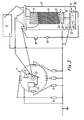
- the device of Figure 1 incorporates a transformer having a core 1, primary winding 2 and secondary winding 3.
- the primary winding 2 is connected to a power supply 4 through a contact breaker device 5 and a switch 6.
- the secondary winding 3 is connected through a conventional distributor 7 to spark plugs 8 in the cylinders of an internal combustion engine.
- the contact breaker device 5 can comprise a conventional arrangement of a rotating cam which operates on a cam follower attached to a contact arm biased by a spring so that the contacts will normally be open. As each lobe of the cam operates on the cam follower the contacts will close so as to complete the circuit through the supply source 4 and the primary windings 2 to the switch 6 shown in Figure 1. The length of time during wnich the supply source is thus connected into the circuit (and therefore the time during which the rapid sequence of sparks are applied to one of the spark plugs 8) will depend upon the length of the cam follower surface of the cam follower.
- the contact breaker device 5 could be replaced by the device of a photocell and a rotating disc incorporating slots which allow light to pass through to the photocell so as to complete the circuit through the switch and the primary winding 2.
- the period during which the spark plug is operative can then of course be modified by varying the length of the slot.
- the switch 6 is connected in parallel with the contact breaker 5 and the condensor 14 is connected directly across the contact breaker and can therefore be the existing condensor present in a conventional circuit.
- An isolating switch 15 enables the switch 6 to be brought into use as and when required or to be isolated if a malfunction should occur; thus enabling the system to operate in a conventional manner under control solely of the contact breaker 5.
- a trip fuse 16 will allow for any overload occurring and this could be associated with a warning light on the dashboard of the vehicle.
- the circuit breaker switch opens the current through the coil 2 will be interrupted resulting in the collapse of the magnetic field, the occurance of a spark in one of the spark plugs 8, and closure of the switch 6. The switch 6 will then open and close intermittently, thus causing a sequence of sparks in the spark plug 8 until such time as the circuit breaker switch reverts to the closed condition.
- the isolating switch 15 could be linked with . the choke of a vehicle so that the switch 6 is only effective during starting whilst the choke is in operation.
- switch 6 could be replaced by a photocell which would be operated by means of a member moving in and out of the light path to the photocell as the plate 9 is intermittently attracted to the transformer core 1. This would remove the possibility of sparking occurring in the control circuit
- Figure 3 illustrates how the circuit of Figure 2 might appear in the actual layout of the ignition system of a vehicle.
- the rotor arm of the distributor 7 has been omitted to show clearly the contact breaker device 5 operated by a cam 19.
- This Figure also illustrates how an auxiliary capacitor 20 might be incorporated into the circuit if the existing capacitor 14 in the conventional ignition system is of too small a value for the modified circuit.
- a conventional vehicle ignition system may readily be adapted to the form illustrated in Figure 2 of the drawings in particular by incorporating the parallel circuit of the switch 6, isolating switch 15 and fuse 16 across the contact breaker 5 and attaching the switch 6 assembly adjacent the end of the transformer casing 17.
- the switch 6 with its associated magnetically attractive plate 9 could be housed within a casing extension 18 (shown in dashed outlined) which is adapted to clip onto the existing casing 17.
- the fuse 16 and isolating switch 15 could be positioned where required.
- the switch 6 and associated parts together with the condenser 14 could be housed in the casing extension 18 clipped onto the casing 17.
- a circuit could readily be incorporated into that of an existing ignition system. Where a complete ignition system is being installed then a custon-made unit comprising the transformer with the switch 6 positioned therebelow within a single casing could be supplied.
- the positioning of the magnetically attractive plate 9 may be modified, as illustrated in Figure 3, so as to be within the main casing 17 and adjacent the ceramic core 21 of the core 1, a pin 22 attached to the plate 9 passing into a hole in the core 21 to act as a bearing member as the plate 9 moves.
- Biasing of the plate 9 away from the core 1 (to cause closure of the switch 6) is achieved by a resilient pad 23, such as of sorbo rubber. Because the plate 9 is much closer to the core 1 in this arrangement, a strong closing bias, by the pad 23, can be provided to ensure positive closure of the switch 6 and a reduction in possible arcing.
- This apparatus can have many uses, some of which are mentioned above. Additionally it could be used to provide a continuous flame (the spark) for the purpose of igniting various materials or fuels or, for example, for the localised destruction of weeds.
Landscapes
- Engineering & Computer Science (AREA)
- Chemical & Material Sciences (AREA)
- Combustion & Propulsion (AREA)
- Mechanical Engineering (AREA)
- General Engineering & Computer Science (AREA)
- Ignition Installations For Internal Combustion Engines (AREA)
Applications Claiming Priority (4)
| Application Number | Priority Date | Filing Date | Title |
|---|---|---|---|
| GB7913499 | 1979-04-18 | ||
| GB7913499 | 1979-04-18 | ||
| GB7943407 | 1979-12-17 | ||
| GB7943407 | 1979-12-17 |
Publications (2)
| Publication Number | Publication Date |
|---|---|
| EP0018217A1 true EP0018217A1 (fr) | 1980-10-29 |
| EP0018217B1 EP0018217B1 (fr) | 1984-08-15 |
Family
ID=26271268
Family Applications (1)
| Application Number | Title | Priority Date | Filing Date |
|---|---|---|---|
| EP19800301257 Expired EP0018217B1 (fr) | 1979-04-18 | 1980-04-18 | Appareil fournissant des impulsions de haute tension |
Country Status (3)
| Country | Link |
|---|---|
| EP (1) | EP0018217B1 (fr) |
| DE (1) | DE3068939D1 (fr) |
| GB (1) | GB2048378B (fr) |
Cited By (1)
| Publication number | Priority date | Publication date | Assignee | Title |
|---|---|---|---|---|
| GB2129491A (en) * | 1982-11-02 | 1984-05-16 | Roy Anderson | Ignition system for an internal combustion engine |
Families Citing this family (1)
| Publication number | Priority date | Publication date | Assignee | Title |
|---|---|---|---|---|
| GB2184782A (en) * | 1985-12-19 | 1987-07-01 | Dawson Royalties Ltd | Ignition systems for internal combustion engines |
Citations (2)
| Publication number | Priority date | Publication date | Assignee | Title |
|---|---|---|---|---|
| US3543740A (en) * | 1968-12-18 | 1970-12-01 | Louis Philippe Duval | Ignition system controlled by a pilot relay |
| FR2036291A6 (fr) * | 1969-03-10 | 1970-12-24 | Mimoun Charles |
-
1980
- 1980-04-18 DE DE8080301257T patent/DE3068939D1/de not_active Expired
- 1980-04-18 EP EP19800301257 patent/EP0018217B1/fr not_active Expired
- 1980-04-18 GB GB8012842A patent/GB2048378B/en not_active Expired
Patent Citations (2)
| Publication number | Priority date | Publication date | Assignee | Title |
|---|---|---|---|---|
| US3543740A (en) * | 1968-12-18 | 1970-12-01 | Louis Philippe Duval | Ignition system controlled by a pilot relay |
| FR2036291A6 (fr) * | 1969-03-10 | 1970-12-24 | Mimoun Charles |
Cited By (1)
| Publication number | Priority date | Publication date | Assignee | Title |
|---|---|---|---|---|
| GB2129491A (en) * | 1982-11-02 | 1984-05-16 | Roy Anderson | Ignition system for an internal combustion engine |
Also Published As
| Publication number | Publication date |
|---|---|
| GB2048378A (en) | 1980-12-10 |
| DE3068939D1 (en) | 1984-09-20 |
| GB2048378B (en) | 1983-04-27 |
| EP0018217B1 (fr) | 1984-08-15 |
Similar Documents
| Publication | Publication Date | Title |
|---|---|---|
| US2203579A (en) | Ignition circuit | |
| US4407255A (en) | Apparatus for supplying high voltage pulses | |
| EP0018217B1 (fr) | Appareil fournissant des impulsions de haute tension | |
| US2837698A (en) | Electrical apparatus | |
| FR1401241A (fr) | Dispositif d'allumage, de protection et de contrôle de flamme, pour brûleur du genre brûleur à mazout ou analogue | |
| CA1161492A (fr) | Dispositif generateur d'impulsions haute tension | |
| US2781412A (en) | Ignition system for internal combustion engines | |
| GB1492296A (en) | Gas-fuelled electric lighter | |
| GB1200645A (en) | Improvements in or relating to cigarette lighters | |
| US4072891A (en) | Timing display ignition plate assembly | |
| ES360196A1 (es) | Perfeccionamientos en encendedores magneticos. | |
| US3273628A (en) | Interrelated gas valve and manual igniter control | |
| US3608534A (en) | Continuing high frequency energy ignition system with improvements | |
| US808958A (en) | Spark-ignition system for explosion-engines. | |
| US2797252A (en) | Inyentor | |
| US3773024A (en) | Ignition system for internal combustion engines | |
| US1057009A (en) | Spark-producing mechanism for internal-combustion engines. | |
| US1063555A (en) | Electric ignition system for internal-combustion engines. | |
| US2568125A (en) | Heater ignition system | |
| US2900575A (en) | Electric ignition systems | |
| US2674663A (en) | Ignition interrupter | |
| US3181522A (en) | Control switch arrangement for a spark plug ignition circuit | |
| US931065A (en) | Electrical interrupter for explosive-engines. | |
| EP0560775A1 (fr) | Dispositif electronique oscillateur pour moteur a combustion interne | |
| US3397031A (en) | Burner ignition system |
Legal Events
| Date | Code | Title | Description |
|---|---|---|---|
| PUAI | Public reference made under article 153(3) epc to a published international application that has entered the european phase |
Free format text: ORIGINAL CODE: 0009012 |
|
| AK | Designated contracting states |
Designated state(s): BE CH DE FR IT LI NL SE |
|
| 17P | Request for examination filed |
Effective date: 19810428 |
|
| ITF | It: translation for a ep patent filed | ||
| GRAA | (expected) grant |
Free format text: ORIGINAL CODE: 0009210 |
|
| RAP1 | Party data changed (applicant data changed or rights of an application transferred) |
Owner name: OCEAN & OVERSEAS SHIPPING COMPANY LIMITED |
|
| AK | Designated contracting states |
Designated state(s): BE CH DE FR IT LI NL SE |
|
| PG25 | Lapsed in a contracting state [announced via postgrant information from national office to epo] |
Ref country code: SE Effective date: 19840815 Ref country code: NL Effective date: 19840815 Ref country code: LI Effective date: 19840815 Ref country code: CH Effective date: 19840815 Ref country code: BE Effective date: 19840815 |
|
| REF | Corresponds to: |
Ref document number: 3068939 Country of ref document: DE Date of ref document: 19840920 |
|
| REG | Reference to a national code |
Ref country code: CH Ref legal event code: PL |
|
| NLV1 | Nl: lapsed or annulled due to failure to fulfill the requirements of art. 29p and 29m of the patents act | ||
| PLBE | No opposition filed within time limit |
Free format text: ORIGINAL CODE: 0009261 |
|
| STAA | Information on the status of an ep patent application or granted ep patent |
Free format text: STATUS: NO OPPOSITION FILED WITHIN TIME LIMIT |
|
| 26N | No opposition filed | ||
| EN | Fr: translation not filed | ||
| ET | Fr: translation filed | ||
| REG | Reference to a national code |
Ref country code: FR Ref legal event code: BR |
|
| PGFP | Annual fee paid to national office [announced via postgrant information from national office to epo] |
Ref country code: FR Payment date: 19920424 Year of fee payment: 13 |
|
| ITTA | It: last paid annual fee | ||
| PGFP | Annual fee paid to national office [announced via postgrant information from national office to epo] |
Ref country code: DE Payment date: 19920626 Year of fee payment: 13 |
|
| PG25 | Lapsed in a contracting state [announced via postgrant information from national office to epo] |
Ref country code: FR Effective date: 19931229 |
|
| PG25 | Lapsed in a contracting state [announced via postgrant information from national office to epo] |
Ref country code: DE Effective date: 19940101 |
|
| REG | Reference to a national code |
Ref country code: FR Ref legal event code: ST |