EP0018220A1 - Vanne à papillon - Google Patents
Vanne à papillon Download PDFInfo
- Publication number
- EP0018220A1 EP0018220A1 EP80301262A EP80301262A EP0018220A1 EP 0018220 A1 EP0018220 A1 EP 0018220A1 EP 80301262 A EP80301262 A EP 80301262A EP 80301262 A EP80301262 A EP 80301262A EP 0018220 A1 EP0018220 A1 EP 0018220A1
- Authority
- EP
- European Patent Office
- Prior art keywords
- valve
- valve member
- seat ring
- sealing surface
- butterfly valve
- Prior art date
- Legal status (The legal status is an assumption and is not a legal conclusion. Google has not performed a legal analysis and makes no representation as to the accuracy of the status listed.)
- Granted
Links
- 238000007789 sealing Methods 0.000 claims abstract description 26
- 239000012530 fluid Substances 0.000 claims description 18
- 230000003247 decreasing effect Effects 0.000 description 5
- 230000000694 effects Effects 0.000 description 3
- 239000000463 material Substances 0.000 description 3
- 239000013013 elastic material Substances 0.000 description 2
- 238000000465 moulding Methods 0.000 description 2
- 238000010276 construction Methods 0.000 description 1
- 239000002184 metal Substances 0.000 description 1
- 230000000149 penetrating effect Effects 0.000 description 1
- 230000001105 regulatory effect Effects 0.000 description 1
- 238000004904 shortening Methods 0.000 description 1
Images



Classifications
-
- F—MECHANICAL ENGINEERING; LIGHTING; HEATING; WEAPONS; BLASTING
- F16—ENGINEERING ELEMENTS AND UNITS; GENERAL MEASURES FOR PRODUCING AND MAINTAINING EFFECTIVE FUNCTIONING OF MACHINES OR INSTALLATIONS; THERMAL INSULATION IN GENERAL
- F16K—VALVES; TAPS; COCKS; ACTUATING-FLOATS; DEVICES FOR VENTING OR AERATING
- F16K1/00—Lift valves or globe valves, i.e. cut-off apparatus with closure members having at least a component of their opening and closing motion perpendicular to the closing faces
- F16K1/16—Lift valves or globe valves, i.e. cut-off apparatus with closure members having at least a component of their opening and closing motion perpendicular to the closing faces with pivoted closure-members
- F16K1/18—Lift valves or globe valves, i.e. cut-off apparatus with closure members having at least a component of their opening and closing motion perpendicular to the closing faces with pivoted closure-members with pivoted discs or flaps
- F16K1/22—Lift valves or globe valves, i.e. cut-off apparatus with closure members having at least a component of their opening and closing motion perpendicular to the closing faces with pivoted closure-members with pivoted discs or flaps with axis of rotation crossing the valve member, e.g. butterfly valves
- F16K1/226—Shaping or arrangements of the sealing
- F16K1/2263—Shaping or arrangements of the sealing the sealing being arranged on the valve seat
- F16K1/2265—Shaping or arrangements of the sealing the sealing being arranged on the valve seat with a channel- or U-shaped seal covering a central body portion
Definitions
- the present invention relates to a butterfly valve adapted to extremely decrease in amount of torque required for rotation of the valve member in opening or shutting fluid path defined by the valve body by means of the valve member.
- a butterfly valve has an annular seat ring made of elastic material such as rubber adapted to be disposed between an inner surface of an annular valve body and a circumference of a disk-shaped valve member for sealing action by pressing the circumference of the valve member on the inner surface of the seat ring in shutting the fluid path defined by the valve member.
- such a type of butterfly valve has a disadvantage that since in rotating a valve member for opening or shutting a fluid path the valve member is rotated intruding itself onto the surface of the seat ring in the neighborhood of the shutting position, relatively large amount of acting torque is required to rotate the valve member even in the neighborhood of a shutting position, resulting in hindering quick action of the valve member when the valve member is operated with a drive means of small amount of output torque and in necessity of a driving means of large capacity, on the contrary, when a drive means of large amount of output torque is adopted for quick operation of opening and shutting the fluid path, and, in addition, another disadvantage that unnecessarily intruding itself onto the seat ring each time of opening and shutting makes the seat ring worn out with result of shortening life of the valve.
- a seat ring of narrow width is provided on the inner surface of the valve body so that the circumference of the valve member is pressed on the seat ring only when the valve member is rotated at the utterly shutting position of the fluid path, or the seat ring is provided with an inwards projecting annular protrusion on the inner surface thereof.
- a type of butterfly valve has been proposed such that the seat ring is provided with a convex protrusion extending circumferentially along the inner surface of the seat ring, a part of the circumference of the valve member does not contact the seat ring depending on an angle of rotation of the valve member during rotation of the valve member, and the total circumference of the valve member is touched on said convex protrusion with predetermined pressure at the utterly shutting position.
- the protrusion is formed to have a certain width, since the circumference of the valve member affects sealing action by intruding to a certain extent into the convex protrusion of the seat ring arranged in the valve body, so that, for instance, when the valve member is rotated from a state of full opening toward a state of full shutting, a portion of the circumference of the valve member in the neighborhood of the valve stem coming into contact with the convex protrusion of the seat ring before other portions, thereafter the valve member is required to be rotated against braking action of the seat ring made of rubber or the like with result of necessitating it to be applied relatively larger amount of rotating torque in order to be brought into a state of full shutting.
- the present invention provides a butterfly valve comprising an annular valve body, a disk-shaped valve member pivotally provided on the annular valve body so as to open and shut the fluid path defined by the annular valve body, and a seat ring having a sealing surface disposed between the valve body and the valve member so as to make sure to shut the fluid path by means of the valve member, the sealing surface of the seat ring being shaped to become wider as it is circumferentially far from a position around the axis of rotation of the valve member.
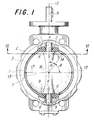
- annular valve body 2 made of rigid material is lined with a ring-shaped valve seat 1 of elastic material such as rubber on an inner circumferential surface and side surface.
- the seat 1 provided with a protrusion 3 integrally formed along circumference thereof is fitted with the valve body 2, having annular protrusions 5 formed at a pair of locations opposed each other and shaped to have a hole 4 substantially positioned at the center thereof as well as to be connected with the protrusion 3.
- the hole 4 penetrates the seat 1, extending into the valve body 2.
- the upper face 6 of the annular protrusion 5 is shaped even to form a sliding surface, and the hole 4 is inserted with a valve stem 8 fixed to the valve member 7 made of rigid material for function of bearing against the stem 8.
- the upper face 6 of the protrusion 5 may be shaped to a concave as shown'in Fig. 9.
- an annular flat surface 9 which slides in contact with the upper face 6 of the annular protrusion 5 in rotating the valve member 7, and substantially from the center of which the stem 8 is protruding.
- the sliding surface 9 is formed with a convexity.
- the upper surface 10 of the circumferential protrusion 3, functioning as a sealing surface, is pressed on the circumference 11 of the valve member 7, when it is set at a position illustrated in Fig. 1 after rotation, so as to ensure the valve member 7 to shut fluid path 31 defined by the valve body 2.
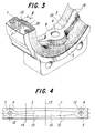
- the sealing surface 10 is formed to have larger width circumferentially in accordance with being far from the neighborhood of the center line 12 of rotation of the valve member 7, that is a line connecting two centers of a pair of holes 4. That is to say, the protrusion 3 is shaped to have a smooth profile 15, the width of which becomes gradually narrower from a position 13 farthest from rotation axis 12 through an intermediate position 14 to a hole 4.
- Fig. 4 shows a plan of a developed seat ring 1, where the median between a pair of holes 4 coincides with the position 13 contacting with the sealing surface 10 into the valve member 7 on the horizontal line 17 perpendicular to the center line 12 through the center 16 of the valve member 7.
- the convex protrusion 3 of the seat ring 1 is shaped to be widest at the position-13 and to become narrower on both sides nearer the holes 4.
- Fig. 5 is a diagrammatic drawing of a valve member 7 and a protrusion 3 seen from the same direction as Fig. 1, and as definitely shown in this drawing, a radius of rotation of the valve member 7 at the position 14 containing an angle 9 at the center 16 with the line 17 perpendicular to the center line 12 of rotation is r cos 6, wherein r is radius of the valve member 7.
- Fig. 5 is a diagrammatic drawing of a valve member 7 and a protrusion 3 seen from the same direction as Fig. 1, and as definitely shown in this drawing, a radius of rotation of the valve member 7 at the position 14 containing an angle 9 at the center 16 with the line 17 perpendicular to the center line 12 of rotation is r cos 6, wherein r is radius of the valve member 7.
- Fig. 5 is a diagrammatic drawing of a valve member 7 and a protrusion 3 seen from the same direction as Fig. 1, and as definitely shown in this drawing, a radius of rotation of the valve member 7 at the position 14 containing an
- FIG. 6 is a cross-sectional drawing showing two positions which the valve member 7 takes when rotated from a position of open toward a position of shutting, in one position the circumference 11 of the valve member 7 being touched on the protrusion 3 of the seat ring 1 from the position 12 to the position 14, and in another position all of the circumference 11 of the valve member 7 being located in the middle of the protrusion 3 of the seat ring 1.
- Fig. 6 shows two positions which the valve member 7 takes when rotated from a position of open toward a position of shutting, in one position the circumference 11 of the valve member 7 being touched on the protrusion 3 of the seat ring 1 from the position 12 to the position 14, and in another position all of the circumference 11 of the valve member 7 being located in the middle of the protrusion 3 of the seat ring 1.
- the circumference 11 of the valve member 7 can be touched or detached substantially at one time in relation to the protrusion 3 of the seat ring 1 in accordance with rotation of the valve member 7, whereby the valve member 7 can be rotated with relatively small amount of rotating torque.
- the profile 15 can be occasionally set apart from the cosine curve, depending on dimension of the valve, thickness of the circumference 11 of the valve member, protruding amount of the convex protrusion 3 of the seat ring 1, or a sectional shape of the protrusion 3 (arcuate, triangular, or frustum-shaped), accordingly the profile 15 can be modified in many ways.
- the profile 15 is fundamentally a function of the angle 6, for example a trigonometric function.
- all parts of the profile 15 are not necessary to be formed in cosine curve but only a part of the profile 15 may be of cosine curve or all of the profile may be formed in a curve corresponding to cosine curve. Further, if all of the profile 15 is formed in cosine curve, the width l of the convex protrusion 3 in the neighborhood of the hole 4 becomes too narrow to be fabricated with sufficient strength of material itself of the seat ring', with sufficient durability or with adequately prepared molding dies, wherefrom it is unnecessary to give all of the profile 15 a cosine curve.
- the width of the protrusion 3 in both of the neighborhood of the valve stem 8 can be taken as longer as possible than a theoretical figure for avoiding insufficient mechanical intensity of the seat ring in the neighborhood of the valve stem and an increase in cost of dies for molding the seat ring.
- the circumference 11 of the valve member 7 is adapted at first to touch the lower portion of the convex protrusion 3 of the seat ring substantially at the one time and gradually to extrude itself onto the seat ring depending on rotation of the valve member 7 with result of increasing in tightness effect. Consequently, in opening or shutting the valve member may be stopped after being rotated to a position where sealing action is sufficiently affected in accordance with fluid pressure in the fluid path, which enables the output torque required for the drive means to be suppressed to minimum torque.
- valve member 7 can be adjusted to be stopped at a position of the convex protrusion 3 higher than a position of stop defined conventionally, so that uniform strength in tightness is obtainable for a long time with result of ensuring long life of the valve.
- the convex protrusion of the seat ring is shaped arcuate in the cross-section protruding inwards as shown in Fig. 3 or 6, the present invention is applicable to a protrusion, for example, having shape of frustrum or triangle straightly tapered on both sides in cross-section.
- the shape of the seal ring itself may be circular, multi-angular, elliptical, or frustrum- shaped and the present invention is able to be applied to these various kinds of shaped of the seat ring.
- the sealing surface of the seat ring 1 may be shaped into an annular concave or groove 19, which ⁇ is narrow in width at the neighborhood of the valve stem 12, as shown in Fig. 8, and in this case the same effect is able to be obtained as the protrusion 3 by adequately determining a locus of an arbitrary position of the circumference 11 of the valve member 7 and curvature of said concave 19.
- Such concave sealing surface 21 results in extending the range of adjustable angle for sealing pressure by means of angle of the valve member.
- the present invention is similarly applicable to a type of eccentric butterfly valve, which has a seat ring holding a perfectly uniform cross-sectional form all over the circumference. Further, the present invention is similarly applicable to a type of butterfly valve having a valve member equipped with an elastic seat ring around circumference thereof, or to a type of butterfly valve having a seat ring integrally on a valve member or a valve body, or in addition, to a type of butterfly valve having a seat ring of metal.
- rotating torque of the valve member can be decreased as much as possible, and necessary rotating torque can be also decreased since an optimum seal characteristic can be set up by regulating the shutting position of the fluid path of the valve member.
- valve member During rotation of a valve member, the valve member is protected from being intruded excessively onto a seat ring, and is able to extend life of the seat ring. Moreover, cost-down can be attained by decreasing in size of drive means disposed outside the valve because of decreasing in rotating torque.
Landscapes
- Engineering & Computer Science (AREA)
- General Engineering & Computer Science (AREA)
- Mechanical Engineering (AREA)
- Lift Valve (AREA)
Priority Applications (1)
| Application Number | Priority Date | Filing Date | Title |
|---|---|---|---|
| AT80301262T ATE4066T1 (de) | 1979-04-20 | 1980-04-18 | Klappenventil. |
Applications Claiming Priority (4)
| Application Number | Priority Date | Filing Date | Title |
|---|---|---|---|
| JP48042/79 | 1979-04-20 | ||
| JP4804279A JPS5825911B2 (ja) | 1979-04-20 | 1979-04-20 | ちよう形弁のシ−トリング |
| JP58717/79 | 1979-05-15 | ||
| JP5871779A JPS5628355A (en) | 1979-05-15 | 1979-05-15 | Sealing mechanism for butterfly valve |
Publications (2)
| Publication Number | Publication Date |
|---|---|
| EP0018220A1 true EP0018220A1 (fr) | 1980-10-29 |
| EP0018220B1 EP0018220B1 (fr) | 1983-07-06 |
Family
ID=26388257
Family Applications (1)
| Application Number | Title | Priority Date | Filing Date |
|---|---|---|---|
| EP80301262A Expired EP0018220B1 (fr) | 1979-04-20 | 1980-04-18 | Vanne à papillon |
Country Status (11)
| Country | Link |
|---|---|
| US (1) | US4289297A (fr) |
| EP (1) | EP0018220B1 (fr) |
| AU (1) | AU526770B2 (fr) |
| BR (1) | BR8002398A (fr) |
| CA (1) | CA1125725A (fr) |
| DE (1) | DE3014854C2 (fr) |
| ES (1) | ES491443A0 (fr) |
| GB (1) | GB2046882B (fr) |
| MX (1) | MX150289A (fr) |
| NO (1) | NO148935C (fr) |
| PH (1) | PH18033A (fr) |
Cited By (4)
| Publication number | Priority date | Publication date | Assignee | Title |
|---|---|---|---|---|
| FR2594200A1 (fr) * | 1986-02-13 | 1987-08-14 | Klein Schanzlin & Becker Ag | Clapet d'arret avec disque a montage centre |
| GB2286651A (en) * | 1994-02-18 | 1995-08-23 | Bray Int Inc | Rotary valve |
| CN104192544A (zh) * | 2014-09-01 | 2014-12-10 | 大唐保定热电厂 | 给煤机速关阀 |
| WO2016162705A1 (fr) * | 2015-04-09 | 2016-10-13 | Ivw D.O.O. | Vanne papillon à bague de siège améliorée effectuant une fermeture de vanne instantanée et produisant une étanchéité croissant de façon uniforme |
Families Citing this family (25)
| Publication number | Priority date | Publication date | Assignee | Title |
|---|---|---|---|---|
| USRE32409E (en) * | 1982-02-04 | 1987-04-28 | Keystone International, Inc. | Valve assembly |
| US4967779A (en) * | 1990-04-09 | 1990-11-06 | Keystone International Holdings Corp. | Method of installing a valve seat in a valve body |
| IT1258340B (it) * | 1992-01-16 | 1996-02-26 | Co Ra Di Lardieri Salvatore | Valvola a farfalla perfezionata per l'intercettazione di sostanze sfuse o fluide in particolare per i settori farmaceutico, chimico e alimentare |
| US5207411A (en) * | 1992-09-30 | 1993-05-04 | Sisk David E | Butterfly valve assembly |
| JP3356511B2 (ja) * | 1993-12-01 | 2002-12-16 | 株式会社オーケーエム | バタフライバルブ |
| US6123318A (en) * | 1999-03-01 | 2000-09-26 | Visteon Global Technologies, Inc. | Throttle body module having improved blade to ledge sealing |
| US7080820B2 (en) | 1999-11-16 | 2006-07-25 | Fisher Controls International Llc. | Elliptical sealing surface for butterfly valve |
| JP2003014139A (ja) * | 2001-07-04 | 2003-01-15 | Okm:Kk | バタフライ弁 |
| JP2004183711A (ja) * | 2002-11-29 | 2004-07-02 | Asahi Organic Chem Ind Co Ltd | バタフライバルブ用シートリング |
| GB2402459B (en) * | 2003-03-28 | 2006-02-01 | Tomoe Technical Res Company Lt | Butterfly valve |
| US20050205824A1 (en) * | 2004-03-18 | 2005-09-22 | Osborne Charles A | Segmented ball control valve with universal end connections |
| CN103003601B (zh) * | 2010-06-29 | 2015-04-01 | 三菱电机株式会社 | 阶梯式阀门 |
| US9057445B2 (en) | 2011-03-04 | 2015-06-16 | Bulk Tank, Inc. | Butterfly valve disc to attain accelerated flow |
| FR2993031B1 (fr) * | 2012-07-04 | 2015-05-01 | Valeo Sys Controle Moteur Sas | Vanne de controle moteur a fonctionnement ameliore |
| US9291273B2 (en) | 2013-09-16 | 2016-03-22 | Bray International, Inc. | Butterfly valve assembly |
| US9924875B2 (en) | 2014-06-13 | 2018-03-27 | The Procter & Gamble Company | Apparatus and methods for modifying keratinous surfaces |
| CA2949129C (fr) | 2014-06-13 | 2020-06-30 | The Procter & Gamble Company | Appareil et procedes de modification de surface keratiniques |
| CA2949123C (fr) | 2014-06-13 | 2019-05-14 | The Procter & Gamble Company | Cartouches pour le depot de compositions de traitement sur des surfaces keratiniques |
| CA2949118C (fr) | 2014-06-13 | 2019-07-23 | The Procter & Gamble Company | Appareil et procedes de modification de surfaces keratiniques |
| US9949552B2 (en) | 2014-07-25 | 2018-04-24 | The Procter & Gamble Company | Handheld treatment apparatus for modifying keratinous surfaces |
| US9955769B2 (en) | 2014-07-25 | 2018-05-01 | The Procter & Gamble Company | Applicator heads for handheld treatment apparatus for modifying keratinous surfaces |
| US11116302B2 (en) | 2015-06-11 | 2021-09-14 | The Procter & Gamble Company | Apparatus and methods for modifying keratinous surfaces |
| AU2016322808B2 (en) | 2015-09-18 | 2019-05-30 | Victaulic Company | Valve and coupling |
| DE102016121721A1 (de) * | 2016-11-14 | 2018-05-17 | Eberspächer Exhaust Technology GmbH & Co. KG | Verfahren zur Herstellung eines Klappenträgers für eine Abgasklappe |
| US10480660B2 (en) * | 2017-09-29 | 2019-11-19 | Mueller International, Llc | Positive hub seal |
Citations (3)
| Publication number | Priority date | Publication date | Assignee | Title |
|---|---|---|---|---|
| US2662545A (en) * | 1951-07-25 | 1953-12-15 | J B Ehrsam & Sons Mfg Co | Self-cleaning butterfly gate |
| US3598365A (en) * | 1969-08-28 | 1971-08-10 | Ladish Co | Butterfly valves |
| DE2503727B2 (de) * | 1975-01-30 | 1978-09-28 | Rheinisches Metallwerk Gmbh Armaturenfabrik, Metall- Und Eisengiesserei, 5000 Koeln | Klappenventil |
Family Cites Families (9)
| Publication number | Priority date | Publication date | Assignee | Title |
|---|---|---|---|---|
| US3314641A (en) * | 1964-04-23 | 1967-04-18 | Hale Company | Butterfly valve |
| US3376015A (en) * | 1964-11-25 | 1968-04-02 | Keystone Valve Corp | High pressure disc valve |
| BE724012A (fr) * | 1968-04-30 | 1969-05-02 | ||
| GB1299508A (en) | 1970-10-29 | 1972-12-13 | Giulio Poliuto Tormene | Butterfly valve |
| GB1320125A (en) * | 1971-04-17 | 1973-06-13 | Ladish Co | Gaskets to provide a circumferential seal when axially and radially compressed an butterfly valves using such gaskets |
| US3840208A (en) * | 1973-05-10 | 1974-10-08 | A Schudel | Bubble-tight inflatable seal for butterfly valve with offset disc |
| US4014511A (en) * | 1976-03-01 | 1977-03-29 | Tomoe Technical Research Company | Butterfly valve |
| US4025050A (en) * | 1976-03-24 | 1977-05-24 | Tomoe Technical Research Company | Butterfly valve |
| DE7826302U1 (de) * | 1978-09-05 | 1978-12-21 | Van Erp Industrieanlagen/Verschleisstechnik, 4130 Moers | Klappenventil |
-
1980
- 1980-04-08 US US06/138,351 patent/US4289297A/en not_active Expired - Lifetime
- 1980-04-11 CA CA349,661A patent/CA1125725A/fr not_active Expired
- 1980-04-14 NO NO801080A patent/NO148935C/no unknown
- 1980-04-16 AU AU57515/80A patent/AU526770B2/en not_active Expired
- 1980-04-17 DE DE3014854A patent/DE3014854C2/de not_active Expired
- 1980-04-17 MX MX182003A patent/MX150289A/es unknown
- 1980-04-18 ES ES491443A patent/ES491443A0/es active Granted
- 1980-04-18 GB GB8012798A patent/GB2046882B/en not_active Expired
- 1980-04-18 EP EP80301262A patent/EP0018220B1/fr not_active Expired
- 1980-04-18 BR BR8002398A patent/BR8002398A/pt not_active IP Right Cessation
- 1980-04-18 PH PH23923A patent/PH18033A/en unknown
Patent Citations (3)
| Publication number | Priority date | Publication date | Assignee | Title |
|---|---|---|---|---|
| US2662545A (en) * | 1951-07-25 | 1953-12-15 | J B Ehrsam & Sons Mfg Co | Self-cleaning butterfly gate |
| US3598365A (en) * | 1969-08-28 | 1971-08-10 | Ladish Co | Butterfly valves |
| DE2503727B2 (de) * | 1975-01-30 | 1978-09-28 | Rheinisches Metallwerk Gmbh Armaturenfabrik, Metall- Und Eisengiesserei, 5000 Koeln | Klappenventil |
Cited By (8)
| Publication number | Priority date | Publication date | Assignee | Title |
|---|---|---|---|---|
| FR2594200A1 (fr) * | 1986-02-13 | 1987-08-14 | Klein Schanzlin & Becker Ag | Clapet d'arret avec disque a montage centre |
| GB2286651A (en) * | 1994-02-18 | 1995-08-23 | Bray Int Inc | Rotary valve |
| GB2286651B (en) * | 1994-02-18 | 1997-11-05 | Bray Int Inc | Rotary valve |
| US5695170A (en) * | 1994-02-18 | 1997-12-09 | Bray International, Inc. | Rotary valve |
| AU685143B2 (en) * | 1994-02-18 | 1998-01-15 | Bray International, Inc. | Rotary valve |
| CN104192544A (zh) * | 2014-09-01 | 2014-12-10 | 大唐保定热电厂 | 给煤机速关阀 |
| WO2016162705A1 (fr) * | 2015-04-09 | 2016-10-13 | Ivw D.O.O. | Vanne papillon à bague de siège améliorée effectuant une fermeture de vanne instantanée et produisant une étanchéité croissant de façon uniforme |
| US10234040B2 (en) | 2015-04-09 | 2019-03-19 | Rami Al-Khoury | Butterfly valve with improved seat ring providing instant valve closing and uniformly increasing sealing |
Also Published As
| Publication number | Publication date |
|---|---|
| GB2046882B (en) | 1983-05-05 |
| NO148935C (no) | 1984-01-11 |
| EP0018220B1 (fr) | 1983-07-06 |
| NO801080L (no) | 1980-10-21 |
| DE3014854A1 (de) | 1980-10-23 |
| DE3014854C2 (de) | 1983-12-01 |
| ES8103322A1 (es) | 1981-02-16 |
| AU5751580A (en) | 1980-10-23 |
| MX150289A (es) | 1984-04-10 |
| ES491443A0 (es) | 1981-02-16 |
| US4289297A (en) | 1981-09-15 |
| NO148935B (no) | 1983-10-03 |
| GB2046882A (en) | 1980-11-19 |
| CA1125725A (fr) | 1982-06-15 |
| AU526770B2 (en) | 1983-01-27 |
| PH18033A (en) | 1985-03-06 |
| BR8002398A (pt) | 1980-12-02 |
Similar Documents
| Publication | Publication Date | Title |
|---|---|---|
| EP0018220A1 (fr) | Vanne à papillon | |
| US5741006A (en) | Butterfly valve | |
| US4411405A (en) | Butterfly-valve | |
| US4058290A (en) | Gate valve | |
| US4605201A (en) | Butterfly valve | |
| US3356336A (en) | Air-tight sealing device for a valve seat of a butterfly valve | |
| US4227675A (en) | Butterfly valve structure and a sleeve therefor | |
| GB2045898A (en) | Gate valve structure | |
| JPS5824685Y2 (ja) | ちよう形弁のシ−トリング | |
| US3765646A (en) | Plug valve seal | |
| US3480254A (en) | Angle seating butterfly valve with skewed disc | |
| US4395017A (en) | Butterfly valve sealing means having an improved O-ring groove | |
| US2978222A (en) | Butterfly or like valves | |
| JP3510764B2 (ja) | ソフト閉止ダンパー機構の開閉弁装置 | |
| US4221360A (en) | Butterfly valve | |
| JPH0714702Y2 (ja) | ボールバルブ | |
| GB2149065A (en) | Valve | |
| JP2598331B2 (ja) | バタフライバルブ | |
| JPH025162Y2 (fr) | ||
| JPS5932763Y2 (ja) | ボ−ルパルプ | |
| JPS5940604Y2 (ja) | バタフライ形制水弁におけるシ−ル装置 | |
| JPS6337570Y2 (fr) | ||
| JPS6210534Y2 (fr) | ||
| KR900700809A (ko) | 스톱밸브 | |
| KR830000878Y1 (ko) | 나비형 밸브의 밸브시이트 |
Legal Events
| Date | Code | Title | Description |
|---|---|---|---|
| PUAI | Public reference made under article 153(3) epc to a published international application that has entered the european phase |
Free format text: ORIGINAL CODE: 0009012 |
|
| AK | Designated contracting states |
Designated state(s): AT BE CH FR IT NL |
|
| 17P | Request for examination filed |
Effective date: 19810416 |
|
| ITCL | It: translation for ep claims filed |
Representative=s name: BARZANO' & ZANARDO S.P.A. |
|
| TCAT | At: translation of patent claims filed | ||
| ITF | It: translation for a ep patent filed | ||
| GRAA | (expected) grant |
Free format text: ORIGINAL CODE: 0009210 |
|
| AK | Designated contracting states |
Designated state(s): AT BE CH FR IT LI NL |
|
| REF | Corresponds to: |
Ref document number: 4066 Country of ref document: AT Date of ref document: 19830715 Kind code of ref document: T |
|
| ET | Fr: translation filed | ||
| PLBE | No opposition filed within time limit |
Free format text: ORIGINAL CODE: 0009261 |
|
| STAA | Information on the status of an ep patent application or granted ep patent |
Free format text: STATUS: NO OPPOSITION FILED WITHIN TIME LIMIT |
|
| 26N | No opposition filed | ||
| ITTA | It: last paid annual fee | ||
| PGFP | Annual fee paid to national office [announced via postgrant information from national office to epo] |
Ref country code: AT Payment date: 19980415 Year of fee payment: 19 |
|
| PGFP | Annual fee paid to national office [announced via postgrant information from national office to epo] |
Ref country code: CH Payment date: 19980507 Year of fee payment: 19 |
|
| PGFP | Annual fee paid to national office [announced via postgrant information from national office to epo] |
Ref country code: FR Payment date: 19990409 Year of fee payment: 20 |
|
| PG25 | Lapsed in a contracting state [announced via postgrant information from national office to epo] |
Ref country code: AT Free format text: LAPSE BECAUSE OF NON-PAYMENT OF DUE FEES Effective date: 19990418 |
|
| PGFP | Annual fee paid to national office [announced via postgrant information from national office to epo] |
Ref country code: NL Payment date: 19990426 Year of fee payment: 20 |
|
| PG25 | Lapsed in a contracting state [announced via postgrant information from national office to epo] |
Ref country code: LI Free format text: LAPSE BECAUSE OF NON-PAYMENT OF DUE FEES Effective date: 19990430 Ref country code: CH Free format text: LAPSE BECAUSE OF NON-PAYMENT OF DUE FEES Effective date: 19990430 |
|
| PGFP | Annual fee paid to national office [announced via postgrant information from national office to epo] |
Ref country code: BE Payment date: 19990614 Year of fee payment: 20 |
|
| REG | Reference to a national code |
Ref country code: CH Ref legal event code: PL |
|
| BE20 | Be: patent expired |
Free format text: 20000418 *TOMOE TECHNICAL RESEARCH CY |
|
| PG25 | Lapsed in a contracting state [announced via postgrant information from national office to epo] |
Ref country code: NL Free format text: LAPSE BECAUSE OF EXPIRATION OF PROTECTION Effective date: 20000418 |
|
| NLV7 | Nl: ceased due to reaching the maximum lifetime of a patent |
Effective date: 20000418 |