EP0018239B1 - Sicherheitsvorrichtung für Schiebeflügel, insbesondere für eine automatisch schliessende Schiebetür - Google Patents
Sicherheitsvorrichtung für Schiebeflügel, insbesondere für eine automatisch schliessende Schiebetür Download PDFInfo
- Publication number
- EP0018239B1 EP0018239B1 EP80400205A EP80400205A EP0018239B1 EP 0018239 B1 EP0018239 B1 EP 0018239B1 EP 80400205 A EP80400205 A EP 80400205A EP 80400205 A EP80400205 A EP 80400205A EP 0018239 B1 EP0018239 B1 EP 0018239B1
- Authority
- EP
- European Patent Office
- Prior art keywords
- safety device
- obstacle
- sheath
- male
- closing
- Prior art date
- Legal status (The legal status is an assumption and is not a legal conclusion. Google has not performed a legal analysis and makes no representation as to the accuracy of the status listed.)
- Expired
Links
- 239000002184 metal Substances 0.000 claims description 7
- 238000006073 displacement reaction Methods 0.000 claims description 3
- 239000013536 elastomeric material Substances 0.000 claims description 2
- 238000009432 framing Methods 0.000 claims 1
- 229920002994 synthetic fiber Polymers 0.000 claims 1
- 238000009434 installation Methods 0.000 description 3
- 230000006835 compression Effects 0.000 description 2
- 238000007906 compression Methods 0.000 description 2
- 239000000463 material Substances 0.000 description 2
- 208000034656 Contusions Diseases 0.000 description 1
- 210000004027 cell Anatomy 0.000 description 1
- 238000004519 manufacturing process Methods 0.000 description 1
- 230000003287 optical effect Effects 0.000 description 1
- 230000035515 penetration Effects 0.000 description 1
- 230000011664 signaling Effects 0.000 description 1
Images

Classifications
-
- B—PERFORMING OPERATIONS; TRANSPORTING
- B66—HOISTING; LIFTING; HAULING
- B66B—ELEVATORS; ESCALATORS OR MOVING WALKWAYS
- B66B13/00—Doors, gates, or other apparatus controlling access to, or exit from, cages or lift well landings
- B66B13/24—Safety devices in passenger lifts, not otherwise provided for, for preventing trapping of passengers
- B66B13/26—Safety devices in passenger lifts, not otherwise provided for, for preventing trapping of passengers between closing doors
-
- E—FIXED CONSTRUCTIONS
- E05—LOCKS; KEYS; WINDOW OR DOOR FITTINGS; SAFES
- E05F—DEVICES FOR MOVING WINGS INTO OPEN OR CLOSED POSITION; CHECKS FOR WINGS; WING FITTINGS NOT OTHERWISE PROVIDED FOR, CONCERNED WITH THE FUNCTIONING OF THE WING
- E05F15/00—Power-operated mechanisms for wings
- E05F15/40—Safety devices, e.g. detection of obstructions or end positions
- E05F15/42—Detection using safety edges
- E05F15/48—Detection using safety edges by transmission of mechanical forces, e.g. rigid or movable members
-
- E—FIXED CONSTRUCTIONS
- E05—LOCKS; KEYS; WINDOW OR DOOR FITTINGS; SAFES
- E05Y—INDEXING SCHEME ASSOCIATED WITH SUBCLASSES E05D AND E05F, RELATING TO CONSTRUCTION ELEMENTS, ELECTRIC CONTROL, POWER SUPPLY, POWER SIGNAL OR TRANSMISSION, USER INTERFACES, MOUNTING OR COUPLING, DETAILS, ACCESSORIES, AUXILIARY OPERATIONS NOT OTHERWISE PROVIDED FOR, APPLICATION THEREOF
- E05Y2900/00—Application of doors, windows, wings or fittings thereof
- E05Y2900/10—Application of doors, windows, wings or fittings thereof for buildings or parts thereof
- E05Y2900/104—Application of doors, windows, wings or fittings thereof for buildings or parts thereof for elevators
-
- E—FIXED CONSTRUCTIONS
- E05—LOCKS; KEYS; WINDOW OR DOOR FITTINGS; SAFES
- E05Y—INDEXING SCHEME ASSOCIATED WITH SUBCLASSES E05D AND E05F, RELATING TO CONSTRUCTION ELEMENTS, ELECTRIC CONTROL, POWER SUPPLY, POWER SIGNAL OR TRANSMISSION, USER INTERFACES, MOUNTING OR COUPLING, DETAILS, ACCESSORIES, AUXILIARY OPERATIONS NOT OTHERWISE PROVIDED FOR, APPLICATION THEREOF
- E05Y2900/00—Application of doors, windows, wings or fittings thereof
- E05Y2900/50—Application of doors, windows, wings or fittings thereof for vehicles
- E05Y2900/53—Type of wing
- E05Y2900/531—Doors
Definitions
- the invention relates to a safety device for sliding leaves, in particular for a sliding door with automatic closing, comprising a movement motor for the mobile leaf or leaves with limited closing force and a non-closing detector for signaling the presence of a obstacle in the joint plane of the uprights coming into said closed position on contact.
- a known safety device of the kind mentioned makes use of detectors for the presence of an obstacle in the plane of the door, capable of preventing the closing or of commanding the instantaneous reopening of the door.
- These optical, pneumatic or mechanical detectors, in particular of the sensitive edge type make it possible to keep flexible edges on the edges of the doors avoiding bruising, but they are fragile and have the drawback of constituting an easy command to reopen the accessible door. to the late notified user. The availability of the installation is thus reduced.
- the closing force of the door is limited to a non-dangerous value and a door non-closing detector signals the presence of an obstacle.
- This device does not provide absolute security and it is ineffective for a thin obstacle, such as a piece of clothing or a dog leash, trapped between closed doors.
- the purpose of the present invention is to remedy these drawbacks and to allow the production of a device guaranteeing user safety and the availability of the installation.
- the safety device according to the invention is characterized in that said uprights carry a song over the whole or almost all of the height respectively a male part and a female conjugate part fitting into said closed position, said parts being dimensioned so that the presence of an obstacle, even of small thickness and flexible, hinders this nesting and closing.
- the preferred application of the invention relates to sliding doors with one or two movable leaves, of transport vehicles, but it is clear that the invention applies to elevator doors and in general to any movable opening panel. .
- the projecting male part is sheathed by a retractable sheath, which carries flexible edges cooperating with conjugate flexible edges fixed edge to the upright carrying the female part.
- a retractable sheath which carries flexible edges cooperating with conjugate flexible edges fixed edge to the upright carrying the female part.
- edges of the flexible lips are preferably profiled to achieve a baffle fit, and the play between the male and female parts is sufficiently small to oppose an interlocking in the presence of an obstacle inserted between the two parts.
- the retractable sheath sheaths the door jamb over the entire height and is arranged to cover all the mechanics while fully retaining the classic aesthetics of the door.
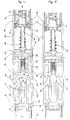
- a metal part 22 having two parallel flanges 24 which confi nent a U-shaped housing 26 open opposite the leaf 12.
- the flanges 24 are flanked externally by seals 28, 30, in a hollow elastic profiled material.
- the rear edge of the seals 28, 30 is embedded by a dovetail 32 in the part 22 and the front edge 34, cut in a bevel, projects from the edge of the U 26. It is easy to see that the whole part 22 , seals 28, 30 constitutes a flexible edge of the leaf 10 having a female U-shaped bee 26.
- a T-shaped metal part 38 On the edge 36 of the upright 16 is fixed by staples 20 a T-shaped metal part 38, shown on an enlarged scale in FIG. 4.
- the sole 40 of the T 38 is attached to the edge 36 and the leg constitutes a blade 42 extending in the median plane of the door 10, 12 and the front part 44 of which engages in the closed position of the door between the flanges 24 in a U shape.
- the blade 42 ends in an end piece 46 made of a hard elastomeric material in the form of a wedge, which in combination with chamfers 48 entering the U 26, facilitates the centering and fitting of the male parts 38 and female 22.
- a plurality of blind holes 50 pass perpendicularly through the sole 40 and extend into the blade 42 by cutting the lateral faces to define guide openings 52 parallel to the direction of translation of the leaf 12.
- a piston 54 In each hole 50 is slidably mounted a piston 54, extended by a rod 56 for supporting a compression spring 58 threaded on the rod 56.
- the spring 58 interposed between a sleeve 60, fitted into the upright 16, and the piston 54 biases the latter in position of engagement in light 52.
- the pistons 54 constitute sliding supports of a sheath 62, arranged at the movable edge of the leaf 12, which frames and covers in the protruding position the blade 42.
- the pistons 54 include countersunk sides 64 which are flush with the blade 42 and carry, fixed by rivets 66, two flanges 68, 70, which frame the blade 42, and whose rear edge 72 overlaps the upright 16.
- the front part of the flanges 68, 70 is constituted by elastic seals 74, 76 analogous to the seals 28, 30 of the leaf 10.
- the front edges 78 of the seals 74, 76 have a shape combined with that 34 of the seals 28, 30, to form in a nested position a baffle seal.
- the sheath 62 constituted by the flanges 68, 70, sheaths the blade 42 and the front edge 78 covers in the protruding position the end piece 46.
- the sheath 62 can be pushed back against the springs 58 in a retracted position in which the pistons 54, sliding in the holes 50, come to bear on the upright 16, the seals 74, 76 coming back from the front part 44 of the blade 42.
- the rear edge 72 of the flanges 68, 70 comes to the level of a recess of the leaf 12, for example of delimitation of a window, to preserve the aesthetics of the door.
- the sheath 62 In the open position of the door the sheath 62 is held projecting by the springs 58 and it hides the blade 42 and the mechanism.
- the edges 34, 78 of the leaves 10, 12 are made of a flexible material.
- the sheath 62 remains projecting (fig. 1) until the two leaves 10, 12 come into contact (fig. 2 ).
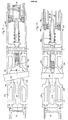
- the seals 28, 30 and 74, 76, the front edges 34, 78 of which have fitted into a baffle constitute a quasi-rigid assembly integral with the leaf 10.
- the door is only closed in appearance and in this intermediate position the detector 90 signals the non-closing.
- the closed position is characterized by a predetermined spacing of the leaves 10, 12 and is signaled by the door closing detector 90 authorizing the starting of the vehicle.
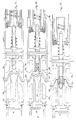
- the door is seen closing on a rigid obstacle 80.
- the lips forming the edges 34, 78 of the seals 28, 30; 74, 76 are supported after a slight deformation on the obstacle 80 and retain the sheath 62.
- a continued movement of closing the leaves 10, 12 causes the advancement of the blade 42 relative to the sheath 62 and the abutment of the end piece 46 on the obstacle 80 with a reduced force equal to the difference between the motor force and the compression force of the springs 58 (fig. 6).
- the obstacle 80 is opposed to the complete closing of the door.
- the obstacle is pinched between the flexible lips and it undergoes the reduced force of the end piece 46 without damage. The user can disengage or clear the obstacle and the door completes its closing.
- Figs. 7 and 8 illustrate the operation in the presence of a thin and rough flexible obstacle 82.
- the obstacle 82 deforms by marrying the chicane shape of the edges 34, 78 (FIG. 7). Subsequently, the jammed obstacle 82 pushes the sheath 62 and the end piece 46 comes into contact with the obstacle 82 in the manner described above. The reduced pressing force of the end piece 46 slightly deforms the obstacle 82, but the sinuous shape of the jammed obstacle 82 and its roughness prevent any sliding of the obstacle between the seals 28, 30; 74, 76 and the continuation of the stroke of the blade 42. The complete closing of the door is prevented (fig. 8).
- a timer causes the reopening and a new closing attempt in a well known manner.
- baffle fitting of the seals 28; 30, 74, 76 and parts 22, 38 ensures a double seal.
Landscapes
- Engineering & Computer Science (AREA)
- Mechanical Engineering (AREA)
- Power-Operated Mechanisms For Wings (AREA)
Claims (10)
Priority Applications (1)
| Application Number | Priority Date | Filing Date | Title |
|---|---|---|---|
| AT80400205T ATE2974T1 (de) | 1979-02-15 | 1980-02-12 | Sicherheitsvorrichtung fuer schiebefluegel, insbesondere fuer eine automatisch schliessende schiebetuer. |
Applications Claiming Priority (2)
| Application Number | Priority Date | Filing Date | Title |
|---|---|---|---|
| FR7904205A FR2449183A1 (fr) | 1979-02-15 | 1979-02-15 | Dispositif de securite pour porte coulissante a fermeture automatique |
| FR7904205 | 1979-02-15 |
Publications (2)
| Publication Number | Publication Date |
|---|---|
| EP0018239A1 EP0018239A1 (de) | 1980-10-29 |
| EP0018239B1 true EP0018239B1 (de) | 1983-04-06 |
Family
ID=9222163
Family Applications (1)
| Application Number | Title | Priority Date | Filing Date |
|---|---|---|---|
| EP80400205A Expired EP0018239B1 (de) | 1979-02-15 | 1980-02-12 | Sicherheitsvorrichtung für Schiebeflügel, insbesondere für eine automatisch schliessende Schiebetür |
Country Status (4)
| Country | Link |
|---|---|
| EP (1) | EP0018239B1 (de) |
| AT (1) | ATE2974T1 (de) |
| DE (1) | DE3062569D1 (de) |
| FR (1) | FR2449183A1 (de) |
Families Citing this family (2)
| Publication number | Priority date | Publication date | Assignee | Title |
|---|---|---|---|---|
| EP0156698A1 (de) * | 1984-03-02 | 1985-10-02 | Poma 2000 S.A. | Sicherheitsvorrichtung für eine sich automatisch schliessende Schiebetür |
| GB8712269D0 (en) * | 1987-05-23 | 1987-07-01 | Overton Ltd Wilfrid | Door control |
Family Cites Families (4)
| Publication number | Priority date | Publication date | Assignee | Title |
|---|---|---|---|---|
| FR1465600A (fr) * | 1965-11-25 | 1967-01-13 | Paris & Du Rhone | Perfectionnement aux lève-glaces électriques pour véhicules automobiles |
| FR2089278A5 (de) * | 1970-04-06 | 1972-01-07 | Chrysler Uk | |
| DE2107254A1 (de) * | 1971-02-16 | 1972-09-07 | Wildt R | Mechanisch elektrische Einklemm sicherung an Omnibus und Bahnturen |
| GB1514570A (en) * | 1975-12-20 | 1978-06-14 | Westinghouse Brake & Signal | Door actuating mechanisms |
-
1979
- 1979-02-15 FR FR7904205A patent/FR2449183A1/fr active Granted
-
1980
- 1980-02-12 AT AT80400205T patent/ATE2974T1/de not_active IP Right Cessation
- 1980-02-12 DE DE8080400205T patent/DE3062569D1/de not_active Expired
- 1980-02-12 EP EP80400205A patent/EP0018239B1/de not_active Expired
Also Published As
| Publication number | Publication date |
|---|---|
| FR2449183B1 (de) | 1982-10-08 |
| DE3062569D1 (en) | 1983-05-11 |
| FR2449183A1 (fr) | 1980-09-12 |
| EP0018239A1 (de) | 1980-10-29 |
| ATE2974T1 (de) | 1983-04-15 |
Similar Documents
| Publication | Publication Date | Title |
|---|---|---|
| EP0544582B1 (de) | Führungsvorrichtung einer Schiebeöffnung, zum Beispiel einer Schiebetür, insbesondere für ein Kraftfahrzeug | |
| FR2513928A1 (fr) | Cartouche de lames de rasoir a lamelle de nettoyage incorporee | |
| EP0018239A1 (de) | Sicherheitsvorrichtung für Schiebeflügel, insbesondere für eine automatisch schliessende Schiebetür | |
| FR2684051A1 (fr) | Dispositif d'etancheite pour panneaux transparents affleurant sur une carrosserie de vehicule. | |
| FR2787498A1 (fr) | Dispositif de securite pour baie vitree a volet mobile | |
| EP0611864B1 (de) | Verriegelung für eine Schiebetür oder eines Schiebefenster | |
| EP0844355A1 (de) | Fahrzeugfensterheber mit Ausgleich der Parallelitätsfehler zwischen den Führungsschienen | |
| EP0156698A1 (de) | Sicherheitsvorrichtung für eine sich automatisch schliessende Schiebetür | |
| EP0345186B1 (de) | Feststeller für italienische, australische und mit Scharnieren versehene Fenster o.dgl. | |
| EP3081725B1 (de) | Zwischenbeschlag für schliesssystem | |
| WO1983001644A1 (fr) | Systeme d'ouverture anti-panique | |
| FR2636092A1 (fr) | Dispositif de verrouillage et deverrouillage automatique de la lame finale d'un rideau ou grille roulant en position de fermeture | |
| EP2687671B1 (de) | Einheit aus einer Schiebetür und ihrem Rahmen, der die in einem Gebäude ausgeführte Öffnung begrenzt | |
| EP1605119B1 (de) | Verriegelungsanordnung für Tür, Fenster oder verschiebbare Fenstertür | |
| FR2766513A1 (fr) | Dispositif d'articulation cachee pour chassis a frappe de porte, fenetre ou analogue | |
| FR3080137A1 (fr) | Element d'ouverture mobile | |
| FR2502677A1 (fr) | Dispositif de guidage en translation et baie coulissante pourvue d'un tel dispositif | |
| FR2729177A1 (fr) | Dispositif de securite a la fermeture pour fenetres, portes et portes-fenetres coulissantes | |
| FR2734311A1 (fr) | Chassis d'occultation a lames | |
| EP0501083A1 (de) | Schutzvorrichtung für Kipptore | |
| FR3080638A1 (fr) | Dispositif de verrouillage pour portes | |
| EP3173564A1 (de) | Rahmen für klappladen | |
| FR2709779A3 (fr) | Verrou de châssis à déverrouillage de sécurité et châssis équipé d'un tel verrou. | |
| FR2503780A1 (fr) | Portillon coulissant pare-balles | |
| FR2508092A1 (fr) | Dispositif formant baie comprenant un element de glace dit " basculant ", et vehicules, batiments equipes avec ce dispositif |
Legal Events
| Date | Code | Title | Description |
|---|---|---|---|
| PUAI | Public reference made under article 153(3) epc to a published international application that has entered the european phase |
Free format text: ORIGINAL CODE: 0009012 |
|
| AK | Designated contracting states |
Designated state(s): AT CH DE GB IT NL SE |
|
| 17P | Request for examination filed |
Effective date: 19810407 |
|
| RAP1 | Party data changed (applicant data changed or rights of an application transferred) |
Owner name: POMA 2000 S.A. |
|
| ITF | It: translation for a ep patent filed | ||
| GRAA | (expected) grant |
Free format text: ORIGINAL CODE: 0009210 |
|
| AK | Designated contracting states |
Designated state(s): AT CH DE GB IT NL SE |
|
| REF | Corresponds to: |
Ref document number: 2974 Country of ref document: AT Date of ref document: 19830415 Kind code of ref document: T |
|
| REF | Corresponds to: |
Ref document number: 3062569 Country of ref document: DE Date of ref document: 19830511 |
|
| PGFP | Annual fee paid to national office [announced via postgrant information from national office to epo] |
Ref country code: CH Payment date: 19840210 Year of fee payment: 5 |
|
| PGFP | Annual fee paid to national office [announced via postgrant information from national office to epo] |
Ref country code: SE Payment date: 19840331 Year of fee payment: 5 |
|
| PGFP | Annual fee paid to national office [announced via postgrant information from national office to epo] |
Ref country code: DE Payment date: 19850228 Year of fee payment: 6 |
|
| PGFP | Annual fee paid to national office [announced via postgrant information from national office to epo] |
Ref country code: AT Payment date: 19860214 Year of fee payment: 7 |
|
| PGFP | Annual fee paid to national office [announced via postgrant information from national office to epo] |
Ref country code: NL Payment date: 19860228 Year of fee payment: 7 |
|
| PG25 | Lapsed in a contracting state [announced via postgrant information from national office to epo] |
Ref country code: AT Effective date: 19870212 |
|
| PG25 | Lapsed in a contracting state [announced via postgrant information from national office to epo] |
Ref country code: SE Effective date: 19870213 |
|
| PG25 | Lapsed in a contracting state [announced via postgrant information from national office to epo] |
Ref country code: CH Effective date: 19870228 |
|
| PG25 | Lapsed in a contracting state [announced via postgrant information from national office to epo] |
Ref country code: NL Effective date: 19870901 |
|
| GBPC | Gb: european patent ceased through non-payment of renewal fee | ||
| NLV4 | Nl: lapsed or anulled due to non-payment of the annual fee | ||
| REG | Reference to a national code |
Ref country code: CH Ref legal event code: PL |
|
| PG25 | Lapsed in a contracting state [announced via postgrant information from national office to epo] |
Ref country code: DE Effective date: 19871103 |
|
| PG25 | Lapsed in a contracting state [announced via postgrant information from national office to epo] |
Ref country code: GB Effective date: 19881118 |
|
| EUG | Se: european patent has lapsed |
Ref document number: 80400205.3 Effective date: 19880215 |
|
| PLBE | No opposition filed within time limit |
Free format text: ORIGINAL CODE: 0009261 |
|
| STAA | Information on the status of an ep patent application or granted ep patent |
Free format text: STATUS: NO OPPOSITION FILED WITHIN TIME LIMIT |