EP0018258A1 - Kraftmehrungsvorrichtung mit Kugeln - Google Patents
Kraftmehrungsvorrichtung mit Kugeln Download PDFInfo
- Publication number
- EP0018258A1 EP0018258A1 EP80400444A EP80400444A EP0018258A1 EP 0018258 A1 EP0018258 A1 EP 0018258A1 EP 80400444 A EP80400444 A EP 80400444A EP 80400444 A EP80400444 A EP 80400444A EP 0018258 A1 EP0018258 A1 EP 0018258A1
- Authority
- EP
- European Patent Office
- Prior art keywords
- piston
- pusher
- flange
- balls
- control chamber
- Prior art date
- Legal status (The legal status is an assumption and is not a legal conclusion. Google has not performed a legal analysis and makes no representation as to the accuracy of the status listed.)
- Withdrawn
Links
- 230000005540 biological transmission Effects 0.000 claims abstract description 14
- 239000000463 material Substances 0.000 claims abstract description 14
- 230000002285 radioactive effect Effects 0.000 abstract description 3
- 231100000331 toxic Toxicity 0.000 abstract description 3
- 230000002588 toxic effect Effects 0.000 abstract description 3
- 239000012530 fluid Substances 0.000 description 6
- 229910000831 Steel Inorganic materials 0.000 description 3
- 239000010959 steel Substances 0.000 description 3
- 238000006073 displacement reaction Methods 0.000 description 2
- 230000002427 irreversible effect Effects 0.000 description 2
- 239000007788 liquid Substances 0.000 description 2
- 230000003321 amplification Effects 0.000 description 1
- 230000000295 complement effect Effects 0.000 description 1
- 230000000694 effects Effects 0.000 description 1
- 230000009347 mechanical transmission Effects 0.000 description 1
- 239000002184 metal Substances 0.000 description 1
- 238000003199 nucleic acid amplification method Methods 0.000 description 1
- 210000000056 organ Anatomy 0.000 description 1
- 239000000941 radioactive substance Substances 0.000 description 1
- 238000003466 welding Methods 0.000 description 1
Images
Classifications
-
- F—MECHANICAL ENGINEERING; LIGHTING; HEATING; WEAPONS; BLASTING
- F16—ENGINEERING ELEMENTS AND UNITS; GENERAL MEASURES FOR PRODUCING AND MAINTAINING EFFECTIVE FUNCTIONING OF MACHINES OR INSTALLATIONS; THERMAL INSULATION IN GENERAL
- F16H—GEARING
- F16H49/00—Other gearings
Definitions
- the invention relates to a force multiplier device and in particular a force multiplier device of the type comprising a body in which a piston is slidably mounted, a control chamber defined between the body and the piston and filled with a transmission material. force and actuating means acting on the force transmission material to bias the piston sliding in the body.
- force multiplier devices of this type are known which are used in the industry each time that an effort must be transmitted and amplified without. that we can have recourse to a purely mechanical transmission system.
- the known force multiplier devices are either pneumatic or hydraulic, that is to say that the force transmission material placed in the control chamber of the device in order to transmit to the piston the force applied by the means of actuation during the implementation of these is a gas or a liquid.
- the subject of the invention is a force multiplier device allowing the transmission and amplification of large forces, in which the risks of leakage inherent in known fluid devices are eliminated, and which are at the same time of simple design and d 'a relatively small footprint.
- a force multiplier device comprising a body in which a piston is slidably mounted, a control chamber defined between the body and the piston and filled with a force transmission material and means actuator acting on - the force transmission material to urge the piston sliding in the body is characterized in that the force transmission material consists of a set of balls of incompressible material filling the control chamber.
- the balls are metallic.
- the actuating means comprise a pusher immobilized in rotation and capable of sliding in the body of the housing to move the balls inside the control chamber.
- the plunger and the piston are then capable of sliding in the body of the housing along axes substantially perpendicular to each other.
- the control chamber can then comprise at least one annular part, the sliding axis of the pusher being substantially tangential to the mean circle defined by this annular part.
- the control chamber may have at rest substantially the shape of a torus, the pusher being substantially cylindrical and of section equal to or less than that of the torus.
- control means further comprise an operating member cooperating with the pusher by means of a connection of the screw-nut type, the pusher being immobilized in rotation and the member maneuver being immobilized in translation and capable of being rotated from outside the housing to slide the pusher in the body of the housing.
- elastic means are provided for bias the piston towards its rest position.
- the body comprises two opposite arms, one of which is capable of being anchored to a counter-flange associated with a pipe, the piston being slidably mounted in the other arm to urge a flange associated with another pipe in leaktight contact with the counter-flange.
- these elastic means can be arranged between the flange and the other arm of the caliper.
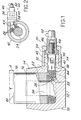
- the jack shown in FIG. 1 comprises a body 10 defining a flat surface 12 intended to be placed on a horizontal work surface. And above which the body 10 defines a cylinder 14 whose axis is substantially perpendicular at the surface 12.
- the cylinder 14 comprises a blind bore 16 in which is received in sliding a piston 18 defining an active surface 20 opposite the surface 12 and substantially parallel thereto.
- the piston 18 also comprises a blind bore 22, opening at the end of the piston opposite the surface 20, in which is received a guide column 24 forming an integral part of the body 10 ; cylinder.
- the piston 18 and the body 10 define between them an annular chamber 26 having at rest substantially the shape of a torus of revolution.
- the chamber 16 is filled with balls 28 of small diameter made of an incompressible material.
- the balls 28 can be metallic and in particular steel and have a diameter of around 2mm. The balls 28 ensure the transmission to the piston 18 of a force applied by actuation means generally designated by the reference 30.
- the actuation means 30 are housed in a bore 32 formed in an appendage 34 of the body 10 of the jack, the bore 32 being closed by an attached cover 36.
- the cover 36 and appendix 34 are designed to pass through a wall of the glove box (not shown) in a leaktight manner, in order to allow the actuator to be actuated from the outside of this box.
- the actuating means 30 comprise a push-button; cylindrical evening 38 capable of sliding in the bore 32, along an axis substantially perpendicular to the sliding axis of the piston 18.
- the pusher 38 is immobilized in rotation relative to the body 10 by means of a pin 40 received in a buttonhole 42 formed in the pusher 38.
- the pusher 38 acts directly by an end face 44 on the balls 28.
- the actuating means 30 further comprise an operating member 46 which cooperates with the other end of the pusher 38 by via a screw-nut type connection 48.
- maneuver 46 is immobilized in translation by means of a flange 50 disposed between the cover 36 and the end of the appendage 34, and it comprises a head 52 projecting outside the cover 36 so as to be able to be biased in rotation by an appropriate operating tool.
- the axis of the actuating means 30 is substantially tangential to the mean circle of the torus defined by the chamber 26 when the jack is at rest and the diameter of the pusher 38 received in the bore 32 is substantially equal to or slightly less than that of the torus, which makes it possible to appreciably increase the stroke of the pusher 38 inside the chamber 26.
- the jack which has just been described with reference to FIGS. 1 and 2 operates as follows:
- the various members constituting the jack occupy the positions shown in FIGS. 1 and 2.
- the surface 12 is placed on a work surface and the cover 36 and the appendage 34 pass through a wall of this enclosure so that only the head 52 of the operating member 46 is accessible from outside the enclosure.
- the part to be lifted is then pressed on the active surface 20 of the piston 18.
- an appropriate tool such as an operating key is engaged on the head 52 of the operating member 46 so as to urge the latter in rotation in the direction corresponding to the movement of the pusher 38 to the left considering Figures 1 and 2 via the screw-nut type connection 48.
- the displacement of the pusher 38 inside the bore 32 has the effect of driving the balls 28 through the end face 44 of pusher 38. Because of their incompressible structure and the fact that chamber 26 is entirely filled with balls, the latter transmits tent the piston 18 the force exerted by the pusher 38, so that the volume of the chamber 26 remains constant.
- the piston 18, guided both by the guide column 24 and by the bore 16 therefore moves upwards when considering FIG. 1 over the desired distance d.
- the reduction ratio is defined both by the pitch of the threads of the screw-nut type connection 48 and by the ratio of the surfaces between the end face 44 of the plunger 38 and the annular underside of the piston 18 on which the balls act 28.
- This double reduction which can be adapted according to the forces to be transmitted can also be modified, in particular as regards the connection of the screw-nut type 48 which may be replaced by any other known reduction gear or to which a third reduction gear of any known type may be added.
- the force multiplier device according to the invention which is of a particularly simple design and of a reduced bulk, also presents the essential advantage of completely eliminating the risks of leaks inherent in pneumatic or hydraulic devices usually used by following the use of the balls 28 in place of the force transmission fluids usually used.
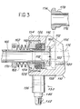
- FIG. 3 shows another force multiplier device according to the invention, particularly suitable for clamping one against the other two flanges making the junction of two pipes when the difficulties of access prohibit the use of usual connection systems.
- the body 110 of the clamping device shown in FIG. 3 comprises two substantially parallel arms 154 and 156 connected by a connection part 158.
- the arm 154 of the body 110 made in two parts in the embodiment shown in Figure 3, is traversed right through by a bore of axis substantially perpendicular to the arms 154 and 156 and defining a part of small diameter 124 and a part of large diameter 116, the latter being disposed on the side of the arm 156.
- An annular piston 118 is slidably mounted in the large diameter portion 116 of the bore and guided inside the small diameter portion 124.
- a control chamber 126 is defined between the piston 118 and the arm 154 of the body 110.
- the chamber 126 is filled with balls made of an incompressible material, for example metallic, such as steel.
- the chamber 12.6 is of annular shape and has at rest substantially the shape of a torus of revolution whose axis is coincident with that of parts 124 and 116 of the bore formed in the arm 154 of the body 110.
- the body 110 of the force multiplier device comprises an appendage (not shown) closed by a cover 136, in which are housed actuating means designated by the general reference 130.
- actuating means 130 include in particular an operating member 146 which projects out of the cover 136 and comprises a head 152 capable of receive an appropriate operating tool.
- the actuating means 130 also comprise a cylindrical pusher (not shown) which cooperates with the balls 128 so as to transmit, by means of these, a control force to the piston 118.
- the section of the pusher is preferably substantially identical to or slightly less than that of the torus formed by the chamber 126 when the device is at rest, and the pusher acts on the balls 128 in a direction substantially tangential to the mean circle defined by this torus, so that the useful stroke of the pusher is as large as possible.
- the piston 118 is pierced with a bore 160 which passes through a flange 162 provided at one of its ends with a flange 164 bearing on an active surface 120 defined at the end - half of the piston 118 opposite the arm 156 of the body 110.
- the flange 162 passes right through the arm 154 of the cylinder body and is extended outside of the latter by a nozzle 166 previously connected, for example by welding, to one of the pipes.
- a return spring 168 is disposed between the arm 154 of the housing 110 and a collar 170 associated with the end piece 166 of the flange 162 so as to allow the tightening to be released.
- the end of the flange 164 disposed opposite the arm 156 of the body of the clamping device comprises an annular groove in which is received a seal 172 formed, for example by a metal O-ring.
- the arm 156 of the body 110 of the jack has the shape of a stirrup capable of bearing on a flange 174 formed on a counter-flange 176 previously connected to the other piping and whose external profile 178 is complementary to the internal profile of a clearance 180 formed in the arm 156.
- the clamping device shown in FIG. 3 is implemented as follows:
- the different organs of the force multiplier device occupy the positions shown in FIG. 3.
- this one is first of all hooked and centered by its arm 156 on the counter-flange 176 as shown diagrammatically in phantom in Figure 3.
- the implementation of the device making it possible to tighten the flange 162 on the counter-flange 176 is then carried out identically to the implementation of the jack described with reference to FIG. 1, using an appropriate operating tool (not shown) adapted to the particular shape of the head 152 of the member maneuver 146.
- the actuator 146 rotationally biased by this tool, trans- 'puts the pusher actuating means 130, movement' of translation driving the balls 128 in the chamber 126. due to the incompressibility balls 128, this results in a displacement to the right, e n considering FIG. 3, of the piston 118.
- the active surface 120 of the piston 118 which cooperates with the flange 164 of the flange 162, thus urges the latter against the flange 174 of the counter-flange 176 until the seal 172 is sufficiently crushed to ensure the tightness of the connection of the two pipes connected respectively to the flange 162 and to the counter-flange 176.
- the clamping device shown in FIG. 3 is released by biasing the operating member 146 in rotation in the direction corresponding to the release of the jack using an appropriate operating tool.
- the irreversible nature of the device resulting from the use. - tion of steel balls 128 in place of the fluid usually used is compensated by the use of the return spring 168 which keeps constant the volume of the chamber 128 by biasing the piston 118 to the left when considering Figure 3 by l 'through the flange 162.
- the clamping device shown in Figure 3 is particularly suitable for performing the junction of pipes ensuring the supply of fluid to removable devices arranged inside a sealed enclosure such as, for example, a glove box inside which experiments are carried out on toxic or radioactive products.
- a sealed enclosure such as, for example, a glove box inside which experiments are carried out on toxic or radioactive products.
- the cover 136 then passes through the wall of the enclosure (not shown) so that the head 152 of the operating member 146 is accessible from outside the enclosure.
- the clamping device shown in Figure 3 is particularly simple in design and compact and the risk of leakage inherent in conventional fluid devices are completely eliminated as a result of l use of rigid balls 129 in place of the liquid or gas usually ensuring the transmission of the control force to the piston.
Landscapes
- Engineering & Computer Science (AREA)
- General Engineering & Computer Science (AREA)
- Mechanical Engineering (AREA)
- Actuator (AREA)
- Bearings For Parts Moving Linearly (AREA)
Applications Claiming Priority (2)
| Application Number | Priority Date | Filing Date | Title |
|---|---|---|---|
| FR7908631 | 1979-04-05 | ||
| FR7908631A FR2453336A1 (fr) | 1979-04-05 | 1979-04-05 | Dispositif multiplicateur d'effort a billes |
Publications (1)
| Publication Number | Publication Date |
|---|---|
| EP0018258A1 true EP0018258A1 (de) | 1980-10-29 |
Family
ID=9224000
Family Applications (1)
| Application Number | Title | Priority Date | Filing Date |
|---|---|---|---|
| EP80400444A Withdrawn EP0018258A1 (de) | 1979-04-05 | 1980-04-02 | Kraftmehrungsvorrichtung mit Kugeln |
Country Status (2)
| Country | Link |
|---|---|
| EP (1) | EP0018258A1 (de) |
| FR (1) | FR2453336A1 (de) |
Cited By (3)
| Publication number | Priority date | Publication date | Assignee | Title |
|---|---|---|---|---|
| US4615228A (en) * | 1984-05-22 | 1986-10-07 | Severinsson Lars M | Device for mechanically transforming a torque into an axial force |
| US4707029A (en) * | 1985-08-07 | 1987-11-17 | Roder Gmbh Sitzmobelworke | Apparatus for supporting parts of furniture |
| CN103453107A (zh) * | 2013-09-16 | 2013-12-18 | 南京工业职业技术学院 | 一种颗粒体传动装置 |
Citations (3)
| Publication number | Priority date | Publication date | Assignee | Title |
|---|---|---|---|---|
| US1346625A (en) * | 1919-09-04 | 1920-07-13 | Jr Robert S Woodward | Power-transmitting apparatus |
| FR1259006A (fr) * | 1960-03-09 | 1961-04-21 | Nouveau vérin | |
| FR1561464A (de) * | 1968-02-15 | 1969-03-28 |
-
1979
- 1979-04-05 FR FR7908631A patent/FR2453336A1/fr not_active Withdrawn
-
1980
- 1980-04-02 EP EP80400444A patent/EP0018258A1/de not_active Withdrawn
Patent Citations (3)
| Publication number | Priority date | Publication date | Assignee | Title |
|---|---|---|---|---|
| US1346625A (en) * | 1919-09-04 | 1920-07-13 | Jr Robert S Woodward | Power-transmitting apparatus |
| FR1259006A (fr) * | 1960-03-09 | 1961-04-21 | Nouveau vérin | |
| FR1561464A (de) * | 1968-02-15 | 1969-03-28 |
Cited By (3)
| Publication number | Priority date | Publication date | Assignee | Title |
|---|---|---|---|---|
| US4615228A (en) * | 1984-05-22 | 1986-10-07 | Severinsson Lars M | Device for mechanically transforming a torque into an axial force |
| US4707029A (en) * | 1985-08-07 | 1987-11-17 | Roder Gmbh Sitzmobelworke | Apparatus for supporting parts of furniture |
| CN103453107A (zh) * | 2013-09-16 | 2013-12-18 | 南京工业职业技术学院 | 一种颗粒体传动装置 |
Also Published As
| Publication number | Publication date |
|---|---|
| FR2453336A1 (fr) | 1980-10-31 |
Similar Documents
| Publication | Publication Date | Title |
|---|---|---|
| EP1526318B1 (de) | Schnellkupplung für die lösbare Verbindung zweier Leitungen und Verwendung einer solchen Kupplung | |
| EP0177397B1 (de) | Ventil mit unwechselbarem Sitz und schneller Instandsetzung | |
| EP0274332B1 (de) | Werkzeuggreifer für Handhabungsgeräte, Roboter und dergleichen | |
| FR2865259A1 (fr) | Raccord rapide et procede de desacouplement des elements male et femelle d'un tel raccord | |
| FR2517790A1 (fr) | Valve a levee equipee d'un soufflet entre l'obturateur et le corps, notamment pour fluides radioactifs ou toxiques | |
| FR2546265A1 (fr) | Raccord de tuyauteries | |
| FR2742837A1 (fr) | Dispositif d'etancheite pour arbre tournant | |
| FR2847330A1 (fr) | Raccord rapide pour la jonction amovible de deux canalisations | |
| EP0805278B1 (de) | Pneumatisch betätigte Einrichtung | |
| EP1618324B1 (de) | Fluidstromregelventilvorrichtung | |
| EP2956702B1 (de) | Manuelle verbindung zum verbinden zweier fluidleitungen | |
| EP0018258A1 (de) | Kraftmehrungsvorrichtung mit Kugeln | |
| EP0163566A1 (de) | Scheibenbremse mit Selbsttätiger Nachstellvorrichtung | |
| EP0306416A1 (de) | Pilot-gesteuertes Sicherheitsventil | |
| EP0196557B1 (de) | Abdichtbare Kupplungsvorrichtung für zwei Fluidleiter | |
| WO2010052386A1 (fr) | Dispositif de raccordement comportant un element d'etancheite | |
| EP0659253B1 (de) | Vorrichtung zur befestigung eines elementes an einem bauteil mit einem flüssigkeitskanal | |
| EP0497647B1 (de) | Ablassschraube für hydraulischen Kreislauf | |
| FR2601610A1 (fr) | Cale perfectionnee pour le maintien en position de serrage de brides sur des pieces destinees a etre immobilisees. | |
| EP0019544B1 (de) | Verschlussvorrichtung für einen Behälter zum Transport eines in einem Kernreaktor bestrahlten Brennstoffstabbündels | |
| EP0124430B1 (de) | Kupplungsvorrichtung mit Fernauslösung | |
| EP0428433A1 (de) | Vorrichtung zum Fixieren der Steuerstabsführungsplatte im Kernreaktordruckgefäss | |
| EP0466564A1 (de) | Auseinandernehmbarer Behälter, der für einen internen Druck ausgelegt ist | |
| EP0443893B1 (de) | Untergruppe eines Bremsbetätigers und Verfahren zum Einstellen einer solchen Untergruppe | |
| EP0034101B1 (de) | Abnehmbare Verbindung, insbesondere zum Verbinden zweier Röhren oder Leitungen |
Legal Events
| Date | Code | Title | Description |
|---|---|---|---|
| PUAI | Public reference made under article 153(3) epc to a published international application that has entered the european phase |
Free format text: ORIGINAL CODE: 0009012 |
|
| AK | Designated contracting states |
Designated state(s): BE DE GB |
|
| STAA | Information on the status of an ep patent application or granted ep patent |
Free format text: STATUS: THE APPLICATION HAS BEEN WITHDRAWN |
|
| 18W | Application withdrawn |
Withdrawal date: 19801031 |
|
| RIN1 | Information on inventor provided before grant (corrected) |
Inventor name: DEBRUS, JEAN |