EP0018295B1 - Überwachungssystem für regenerative Verstärker enthaltende Fernmeldeverbindungen - Google Patents
Überwachungssystem für regenerative Verstärker enthaltende Fernmeldeverbindungen Download PDFInfo
- Publication number
- EP0018295B1 EP0018295B1 EP80400542A EP80400542A EP0018295B1 EP 0018295 B1 EP0018295 B1 EP 0018295B1 EP 80400542 A EP80400542 A EP 80400542A EP 80400542 A EP80400542 A EP 80400542A EP 0018295 B1 EP0018295 B1 EP 0018295B1
- Authority
- EP
- European Patent Office
- Prior art keywords
- repeater
- error
- regenerator
- low frequency
- frequency signal
- Prior art date
- Legal status (The legal status is an assumption and is not a legal conclusion. Google has not performed a legal analysis and makes no representation as to the accuracy of the status listed.)
- Expired
Links
- 238000012544 monitoring process Methods 0.000 title claims description 29
- 230000001360 synchronised effect Effects 0.000 claims description 2
- 230000001419 dependent effect Effects 0.000 claims 1
- 230000005540 biological transmission Effects 0.000 description 5
- 238000001514 detection method Methods 0.000 description 4
- 230000002763 arrhythmic effect Effects 0.000 description 3
- 230000003321 amplification Effects 0.000 description 2
- 239000000969 carrier Substances 0.000 description 2
- 238000003199 nucleic acid amplification method Methods 0.000 description 2
- 230000002950 deficient Effects 0.000 description 1
- 238000010586 diagram Methods 0.000 description 1
- 230000000737 periodic effect Effects 0.000 description 1
- 238000005070 sampling Methods 0.000 description 1
- 238000000926 separation method Methods 0.000 description 1
- 230000011664 signaling Effects 0.000 description 1
- 230000001502 supplementing effect Effects 0.000 description 1
- 238000011144 upstream manufacturing Methods 0.000 description 1
Images


Classifications
-
- H—ELECTRICITY
- H04—ELECTRIC COMMUNICATION TECHNIQUE
- H04B—TRANSMISSION
- H04B17/00—Monitoring; Testing
- H04B17/40—Monitoring; Testing of relay systems
Definitions
- the invention relates generally to transmission links by frequency division multiplex signals and by time division multiplex signals, equipped with repeater-regenerators. More particularly, it relates to a system in accordance with the preamble of claim 1 for monitoring repeater-regenerators inserted in parallel on a telecommunications link between a monitoring station and a monitored station and for monitoring the performance thereof and identifying the repeater-regenerators defective. More specifically, the function of this monitoring system is to transmit to a control and command point information relating to the operating and correct operating condition of the repeater-regenerators, this control and command point. normally being the monitoring station.
- the error information to be collected in each repeater-regenerator is obtained by sampling the state of a certain number of flip-flops for alarm triggering and by counting the number of errors on the code used online and by coding this. number.
- the table of binary values thus obtained is stored in a register in the repeater-regenerator. For example, if the online code is the bipolar code, the error detection circuit counts the number of bipolar rapes. If the online code is the HDBn code, the error detection circuit counts the number of sequences containing more than n zeros.
- the binary data table in the register is then pulsed out of the register at a rate provided for the supervision signals and is used to modulate a carrier.
- the resulting signal can then be demodulated at the end of the line and interpreted as appropriate.
- each repeater-regenerator is provided with an error detector and counter, the output of which feeds an error rate coder, itself connected to a supervision register.
- the repeater-regenerator receives a time division multiplex frame with a frame alignment word, and it comprises means for restoring the clock pulses of the frame and means for counting the successive time slots of the frame and means for introducing the content of the supervision register into the time slot whose number is assigned to the repeater-regenerator.
- Such a system is not suitable for monitoring a link equipped with two-way repeater-regenerators in which the supervision information produced in a given repeater-regenerator is sent from this repeater-regenerator to the monitoring station. , by way of return.
- the frame advances in the forward direction while in a two-direction repeater-regenerator system, each time slot in the frame, when filled in a given repeater-regenerator would have to do turn around by the return route. Everything happens as if the frame lost a time slot at each repeater-regenerator and the system of the aforementioned American patent could not be suitable for a four-wire connection.
- control signal in the link must include both a low frequency signal and the clock signals defining the time division multiplex frame and the repeater-regenerators must include means for recovering d 'clock.
- the object of the present invention is to provide a system for monitoring repeaters-regenerators in two directions in a two-way propagation link which comprises only a single low frequency signal modulated and mixed in frequency with the data signals to be transmitted. in the forward channel for controlling the transmission of error data signals from each repeater-regenerator to the monitoring station and which is also reused to modulate the error data signals transmitted on the return channel .
- the repeater-regenerator monitoring system is as defined in claim 1.
- a supervision word is stored in a shift register and the read progress pulses of said shift register are obtained by frequency division of the frequency of the low frequency signal modulated by the control pulses.
- the supervision word is completed by a start bit, a stop bit, and possibly a parity bit and several bits forming the address of the repeater-regenerator.
- the supervision word thus completed is used to modulate the low frequency signal and the modulating start-stop supervision word is sent to the monitoring station.
- reference numbers 1 and 2 respectively designate the monitoring station and the monitored station. These two stations are connected by two coaxial lines 3 and 4 along which are arranged, at regular intervals, two-directional repeater-regenerators, only two of which are represented and designated by P and P + 1.
- the monitoring station 1 sends, to the monitored station 2 on the so-called coaxial line 3, analog signals, or digital data signals, a signal at a predetermined low frequency modulated by periodic control pulses LF 1 and a supply current.
- the monitoring station 1 receives, via the coaxial line 4, the low frequency signal LF 1 modulated by the completed supervision words supplied by the repeater-regenerators and the return of the supply current. It should be noted that each two-direction repeater-regenerator is supplied at two points by the supply current from the forward coaxial line 3 and the return coaxial line 4.
- the coaxial line to go 3 enters the repeater-regenerator by terminal 31 and the coaxial line to go 3 leaves the repeater-regenerator by terminal 32.
- the coaxial return line 4 enters the repeater-regenerator via terminal 41 and the coaxial return line 4 leaves the re fart-regenerator via terminal 42.
- the input terminals 31 and 41 are respectively connected to the input terminals 3011 and 4011 of directional input filters 301 and 401 which separate, from each other, the data signals, the control pulses modulating the signal at low frequency and direct current supply.
- the data signals appear on the output terminals 3012 and 4012 of the directional input filters 301 and 401 respectively and, from there, they are applied to the amplifier-regenerators of forward 302 and return 402 of repeater-regenerator P , then to the directional output filters 303 and 403, respectively.
- the output terminals 3012 and 4012 of the directional input filters 301 and 401 are connected to the input terminals 3021 and 4021 of the amplifier-regenerators 302 and 402.
- the output terminals 3022 and 4022 of these amplifier-regenerators are connected to the input terminals 3032 and 4032 of the directional output filters 303 and 403 and the output terminals 3031 and 4031 of these directional output filters are connected to terminals 32 and 42 of the two-direction repeater-regenerator P .
- the control pulses appear on the output terminal 3013 of the directional input filter 301 which is connected to the input terminal 3041 of a control pulse amplifier 304 in which the low frequency signal modulated by the control pulses is amplified. After amplification, the control pulses available on the output terminal 3042 of the amplifier 304 are applied to the input terminal 3033 of the directional output filter 303.
- a channel for direct current, respectively 33 and 43 is provided between the directional input and output filters 301 and 303, and 401 and 403, each of these channels comprising, inserted in the channel, a circuit d power supply, respectively 34 and 44.
- the amplifier-regenerators themselves 302 and 402 have outputs 3023 and 4023 connected to inputs 3051 and 4051 of two error detectors and counters 305 and 405. These detectors and error counters have their outputs 3053 and 4053 connected to inputs 3071 and 3072 of an encoder 307. Finally, the outputs 3073 of the encoder are connected to the corresponding parallel loading inputs of a shift register 308.
- the output terminal 3013 of the directional filter 301 is connected to the input 3061 of a demodulator 306 and to the input 3101 of a modulator 310.
- An output terminal 3062 of the demodulator 306 delivers a first pulse to terminals 3052 and 4052 to control the transfer of the error data from the detectors and error counters 305 and 405 to the encoder 307 as well as the erasure of these detectors and error counters.
- Another output terminal 3063 of the demodulator 306 delivers a second pulse to a terminal 3083 to command the loading of the coded error data from the coder 307 into the shift register 308.
- shift register 308 is also loaded with a 1 at its highest binary weight stage and by a 0 at its zero binary stage.
- register 308 can also be loaded with a parity bit and several bits forming the address of the repeater-regenerator, which are recorded in a read-only memory.
- the word thus loaded forms the completed error supervision word.
- the completed error supervision word thus forms an arrhythmic start-stop word such as the words which represent the characters in a telex telegraph link.
- the demodulator 306 demodulates control pulses modulating the signal at low frequency, having a relatively long duration. From the leading edge of each demodulated pulse, the demodulator 306 produces three successive pulses as already said.
- the first pulse is intended for transferring the error data from the detectors and error counters 305 and 405 to the encoder 307 and for erasing the detectors and error encoders through the terminals 3052 and 4052
- the second pulse is intended for loading the shift register 308 by the error data and by the start and stop bits and others completing the supervision word through terminal 3083.
- a third pulse is intended for synchronization of a frequency divider 309 through terminals 3064 and 3091.
- the frequency divider 309 receives by its terminal 3093 the low frequency signal LF 1 and by its terminal 3091 the synchronization pulse coming from the demodulator 306 and it produces on its output terminal 3092 read progress pulses for the register at offset 308 which are applied to the latter by a terminal 3084.
- the encoder 307 can be of any known type. Two examples of error monitoring code are given in Tables 1 and II below:
- the low frequency signal LF is also applied to the input terminal 3101 of the modulator 310 which receives the bits read from the error supervision word exiting in series from the shift register 308, through the terminals 3082 and 3102 and applies to the directional filter 403, through terminals 3103 and 4033, the low frequency signal modulated by the error supervision bits.
- the predetermined frequency of the low frequency signal LF can be 4 kHz and the division factor of the frequency divider 309 can be 32.
- the cadence of the read pulses at terminal 3092 of the frequency divider, and so the bit rate is thus 125 bits per second.
- the low frequency LF signal crosses the repeater-regenerators in the direction of going by following a bypass path 301, 304, 303 in which it is amplified and is also looped between the input terminal 31 of the forward line and the output terminal 42 of the return line in each repeater-regenerator, the loop comprising a modulator 310 in series and a demodulator 306 in parallel.
- the demodulator 306 associated with a frequency divider 309 controls the error detectors and counters 305, 405 and the error supervision word register 308 and the word contained in this register is used to modulate the low frequency signal looped through the modulator 310 which thus transmits to the monitoring station the error supervision information.
- the completed error supervision words modulating the low frequency signal LF cross in the return direction of other repeater-regenerators.
- the data signals and the modulated low-frequency signal are separated in the input directional filter 401, then the modulated low-frequency signal is applied through terminals 4013 and 4061 to a demodulator 406.
- the output terminal 4062 of the demodulator 406 delivers to the output terminal 3081 of the shift register 308 the serialized bits of the supervised error supervision words coming from the repeater-regenerators upstream of the repeater-regenerator considered on the return line.
- the error supervision words from the other repeater-regenerators are treated like the error supervision words from the coder of the repeater-regenerator considered, except that they already have their start bits, stop and possibly address, it is not necessary to add these bits to them.
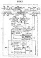
- Fig. 3 represents the monitoring station. It includes a local two-way repeater-regenerator which includes for the forward direction an end amplifier-regenerator 502 absolutely identical to the amplifier-regenerator 302 and for the return direction an end amplifier-regenerator 602 absolutely identical to amplifier-regenerator 402.
- the local repeater-regenerator also includes detectors and error counters 505 and 605, an encoder 507, a shift register 508, a demodulator 506, a frequency divider 509 and a demodulator 606 which have functions respectively similar to those of the detectors and error counters 305 and 405, the encoder 307, the shift register 308, the demodulator 306, the frequency divider 309 and the demodulator 406.
- the circuits and the circuit terminals having the same functions in FIGS. 2 and 3 have reference numbers which differ from 200 from one another. As the circuits having corresponding reference numbers in FIGS. 2 and 3 are identical, it is not necessary to describe them a second time.
- a data source 501 such as the modulation circuit of a modem receives by its input terminal 5011 the baseband data signals from a transmitter (not shown) and a carrier wave and is connected, through terminals 5012 and 5021 to the forward direction amplifier-regenerator 502.
- the return direction amplifier-regenerator 602 is connected, via terminals 6022 and 6032, to a data receiver 603 such as the modem demodulation circuit which transmits via its terminal 6031 the baseband data signals to a data receiver (not shown) such as a printer.
- the circuits 501 and 603 also comprise means of separation between the carrier wave modulated by the data signals and a supply current.
- the carrier wave has a frequency different from the frequency of the LFi signal.
- the monitoring station 1 also comprises a data processing stage 700 composed of a processing circuit 701 and a display circuit 702.
- the data processing circuit 701 comprises a circuit for recognizing the start and stop bits and possibly address words supplementing the error supervision words coming from the shift register 508 and a decoder which decodes the error data, this decoder being similar to those used in start-stop arrhythmic teletypewriters. These words are decoded according to the preceding table I or II in the form of characters which are displayed by the display circuit 702.
- the data processing circuit 701 also comprises means for producing a pulse initializing the start of the acquisition cycle.
- This pulse initialization activates a monostable flip-flop 703 through terminals 7012 and 7031.
- the monostable flip-flop 703 provides a control pulse to a gate circuit 705 which allows the low frequency signal LF 1 to pass for the duration of the control pulse. produced by a generator 704.
- the low frequency signal LF modulated by the control pulse, is applied to the input terminal 5033 of the directional output filter 503, to the input terminal 5061 of the demodulator 506 and to the input terminal 5093 of the divider. of frequency 509.
Landscapes
- Physics & Mathematics (AREA)
- Electromagnetism (AREA)
- Engineering & Computer Science (AREA)
- Computer Networks & Wireless Communication (AREA)
- Signal Processing (AREA)
- Monitoring And Testing Of Transmission In General (AREA)
- Dc Digital Transmission (AREA)
- Time-Division Multiplex Systems (AREA)
Claims (4)
Applications Claiming Priority (2)
| Application Number | Priority Date | Filing Date | Title |
|---|---|---|---|
| FR7909840 | 1979-04-19 | ||
| FR7909840A FR2454728A1 (fr) | 1979-04-19 | 1979-04-19 | Procede et dispositif de telesurveillance de liaisons numeriques ou analogique de telecommunications |
Publications (3)
| Publication Number | Publication Date |
|---|---|
| EP0018295A2 EP0018295A2 (de) | 1980-10-29 |
| EP0018295A3 EP0018295A3 (en) | 1981-01-07 |
| EP0018295B1 true EP0018295B1 (de) | 1983-04-06 |
Family
ID=9224477
Family Applications (1)
| Application Number | Title | Priority Date | Filing Date |
|---|---|---|---|
| EP80400542A Expired EP0018295B1 (de) | 1979-04-19 | 1980-04-21 | Überwachungssystem für regenerative Verstärker enthaltende Fernmeldeverbindungen |
Country Status (5)
| Country | Link |
|---|---|
| US (1) | US4334303A (de) |
| EP (1) | EP0018295B1 (de) |
| CA (1) | CA1136729A (de) |
| DE (1) | DE3062588D1 (de) |
| FR (1) | FR2454728A1 (de) |
Families Citing this family (26)
| Publication number | Priority date | Publication date | Assignee | Title |
|---|---|---|---|---|
| US4451916A (en) * | 1980-05-12 | 1984-05-29 | Harris Corporation | Repeatered, multi-channel fiber optic communication network having fault isolation system |
| ATE10320T1 (de) * | 1980-06-16 | 1984-11-15 | The Post Office | Digitale uebertragungssysteme. |
| FR2524231A1 (fr) * | 1982-03-29 | 1983-09-30 | Telecommunications Sa | Procede pour transmettre un signal en code hdbn avec un signal binaire auxiliaire, codeur et decodeur selon le procede et systeme de telesurveillance de repeteurs d'une liaison numerique au moyen de tels signaux auxiliaires |
| DE3211977A1 (de) * | 1982-03-31 | 1983-10-06 | Siemens Ag | Betriebsueberwachung von uebertragungsstrecken fuer digitale signale |
| FR2534428A1 (fr) * | 1982-10-12 | 1984-04-13 | Cit Alcatel | Systeme d'exploitation et de maintenance d'equipements repartis le long d'une liaison de transmission numerique |
| US4490817A (en) * | 1982-12-13 | 1984-12-25 | At&T Bell Laboratories | Packet error rate measurements by distributed controllers |
| DE3310795A1 (de) * | 1983-03-24 | 1984-09-27 | Philips Kommunikations Industrie AG, 8500 Nürnberg | Ueberwachungssystem fuer ein digitales uebertragungssystem |
| IT1161837B (it) * | 1983-05-18 | 1987-03-18 | Telettra Lab Telefon | Sistema e apparecchiatura per la telesorveglianza di trasmissioni di dati |
| US4519070A (en) * | 1984-01-19 | 1985-05-21 | Burroughs Corporation | Method of initializing and recovering from failures in a local area network |
| JPS60240230A (ja) * | 1984-05-15 | 1985-11-29 | Nec Corp | 受信デ−タ処理装置 |
| JPS60241351A (ja) * | 1984-05-16 | 1985-11-30 | Kokusai Denshin Denwa Co Ltd <Kdd> | 光中継器監視方式 |
| EP0208327B1 (de) * | 1985-07-11 | 1991-07-24 | Siemens Aktiengesellschaft | Digitaler Teilnehmeranschluss |
| JPS6374234A (ja) * | 1986-09-17 | 1988-04-04 | Nec Corp | 多方向多重通信システム |
| DE3638147A1 (de) * | 1986-11-08 | 1988-05-11 | Standard Elektrik Lorenz Ag | Digitales nachrichtenuebertragungssystem mit adressen aufweisenden zwischenregeneratoren und einrichtung zur fehlerortung |
| JPH0622353B2 (ja) * | 1988-11-28 | 1994-03-23 | 富士通株式会社 | 伝送路の監視方式 |
| US5287343A (en) * | 1991-02-25 | 1994-02-15 | Matsushita Electric Works, Ltd. | Network administration system |
| US5517519A (en) * | 1993-06-14 | 1996-05-14 | International Business Machines Corporation | Apparatus for repowering and monitoring serial links |
| US5659575A (en) * | 1995-04-28 | 1997-08-19 | Grinnell Corporation | Method and apparatus for improving data regeneration in asynchronous network communication |
| US8064369B1 (en) * | 1998-12-01 | 2011-11-22 | Qwest Communications International Inc | System and method for increasing distribution distance of XDSL type signals |
| US6625116B1 (en) * | 1999-05-07 | 2003-09-23 | Adtran, Inc. | System, methods and apparatus for increasing the data rate on an existing repeatered telecommunication channel structure |
| US6236664B1 (en) * | 1999-06-04 | 2001-05-22 | Terayon Communications Systems, Inc. | Pair gain system with an ADSL repeater unit |
| US7194023B2 (en) * | 2001-02-06 | 2007-03-20 | 2Wire, Inc. | Loop extender with communications, control, and diagnostics |
| US7483528B2 (en) * | 2001-02-06 | 2009-01-27 | 2Wire, Inc. | Loop extender with selectable line termination and equalization |
| US8520835B2 (en) * | 2006-04-18 | 2013-08-27 | 2Wire, Inc. | Method and apparatus for providing power to a network interface device via telephone lines |
| US7965977B2 (en) * | 2006-04-18 | 2011-06-21 | 2Wire, Inc. | Remote antenna system |
| US8934775B2 (en) * | 2007-07-23 | 2015-01-13 | Tyco Electronics Subsea Communications Llc | System and method for signaling between elements in an undersea optical communication system and system incorporating the same |
Citations (1)
| Publication number | Priority date | Publication date | Assignee | Title |
|---|---|---|---|---|
| US3987395A (en) * | 1974-06-28 | 1976-10-19 | Compagnie Industrielle Des Telecommunications Cit-Alcatel | Arrangement of high frequency pulse regenerative repeaters |
Family Cites Families (5)
| Publication number | Priority date | Publication date | Assignee | Title |
|---|---|---|---|---|
| US2514367A (en) * | 1946-09-12 | 1950-07-11 | Rca Corp | Fault locating for radio relay systems |
| US3458661A (en) * | 1966-06-21 | 1969-07-29 | Bell Telephone Labor Inc | Arrangement for providing partial service on a failed serially looped carrier system |
| US4083003A (en) * | 1973-11-05 | 1978-04-04 | Products Of Information Technology, Inc. | Vehicle location system |
| DE2522441C2 (de) * | 1975-05-21 | 1985-02-21 | Hans Kolbe & Co, 3202 Bad Salzdetfurth | Überwachungssystem für elektronische Baugruppen oder Geräte in drahtgebundenen Fernmeldeanlagen |
| DE2725152C2 (de) * | 1975-05-21 | 1986-03-13 | Hans Kolbe & Co, 3202 Bad Salzdetfurth | Überwachungssystem für elektronische Baugruppen oder Geräte in drahtgebundenen Fernmeldeanlagen |
-
1979
- 1979-04-19 FR FR7909840A patent/FR2454728A1/fr active Granted
-
1980
- 1980-04-18 CA CA000350177A patent/CA1136729A/en not_active Expired
- 1980-04-18 US US06/141,679 patent/US4334303A/en not_active Expired - Lifetime
- 1980-04-21 EP EP80400542A patent/EP0018295B1/de not_active Expired
- 1980-04-21 DE DE8080400542T patent/DE3062588D1/de not_active Expired
Patent Citations (1)
| Publication number | Priority date | Publication date | Assignee | Title |
|---|---|---|---|---|
| US3987395A (en) * | 1974-06-28 | 1976-10-19 | Compagnie Industrielle Des Telecommunications Cit-Alcatel | Arrangement of high frequency pulse regenerative repeaters |
Non-Patent Citations (1)
| Title |
|---|
| "A 120 Mb/s DIGITAL TRANSMISSION SYSTEM ON COAXIAL CABLE" P.J. WAKELING - POINT-TO-POINT COMMUNICATION. Vol. 18 No. 1 Janvier 1974 * |
Also Published As
| Publication number | Publication date |
|---|---|
| CA1136729A (en) | 1982-11-30 |
| EP0018295A3 (en) | 1981-01-07 |
| DE3062588D1 (en) | 1983-05-11 |
| US4334303A (en) | 1982-06-08 |
| FR2454728B1 (de) | 1982-04-02 |
| FR2454728A1 (fr) | 1980-11-14 |
| EP0018295A2 (de) | 1980-10-29 |
Similar Documents
| Publication | Publication Date | Title |
|---|---|---|
| EP0018295B1 (de) | Überwachungssystem für regenerative Verstärker enthaltende Fernmeldeverbindungen | |
| EP0026135B1 (de) | Verfahren zum Prüfen einer Digitaldatenübertragungsleitung zwischen zwei Modems und Vorrichtung zur Durchführung dieses Verfahrens | |
| CA2108209C (fr) | Methode et systeme de transmission sismique utilisant des unites de concentration | |
| CA1296775C (fr) | Methode et systeme de transmission semi-sequentielle utilisant simultanement plusieurs frequences de transmission radio pour relier un ensemble de reception sismique a un laboratoire central de commande et d'enregistrement | |
| EP0064120B1 (de) | Verfahren zum Bestimmen der Konfiguration der aktiven Kanäle in einem Multiplex-Übertragungssystem und Einrichtung dafür | |
| EP0094322B1 (de) | Koppler hoher Durchgangsrate zwischen einem PCM-Multiplex und einer Paketvermittlung | |
| FR2522829A1 (fr) | Dispositif de detection du passage d'etiquettes a proximite d'un poste de controle | |
| FR2600473A1 (fr) | Dispositif de multiplexage pour un systeme de transmission numerique | |
| FR2519820A1 (fr) | Multiplexeur demultiplexeur asynchrome numerique temporel | |
| FR2544154A1 (fr) | Systeme de transmission des donnees pour des flutes sismiques | |
| FR2462064A1 (fr) | Appareil recepteur pour convertir des donnees binaires codees optiquement en signaux electriques | |
| EP0035061B1 (de) | Verfahren und Vorrichtung zum Multiplexen eines Datensignals und mehrerer sekundärer Signale, zugehörige Verfahren und Vorrichtungen zum Demultiplexen und Schnittstellen-Sender und -Empfänger dafür | |
| EP0090728B1 (de) | Verfahren zur gemeinsamen Übertragung eines Signals im HDBN-Kode und eines binären Hilfssignals, Kodierer und Dekodierer nach diesem Verfahren und System zur Fernüberwachung von Zwischenverstärkern einer Digitalverbindung mit Hilfe solcher Hilfssignale | |
| FR2466921A1 (fr) | Appareil d'affectation et de selection de parties de canaux de transmission de donnees | |
| EP0097579B1 (de) | Funkverbindungssystem nach dem Frequenzsprungverfahren mit Redundanz zwischen den einzelnen Frequenzstufen | |
| FR2670594A1 (fr) | Carte portative de reception de messages personnels. | |
| EP0082054B1 (de) | Verfahren zur Synchronisierung der Sende-Empfangsgeräte in einem Frequenzsprungnetz und Gerät zur Ausführung dieses Verfahrens | |
| EP0355073B1 (de) | Verfahren zur Synchronisation und Anordnung zur Synchronisationsrückgewinnung für Übertragung in Zeitgetrenntlage | |
| EP0025767A1 (de) | Verfahren und Vorrichtung zum automatischen Prüfen eines digitalen Datenübertragungssystems | |
| FR2571917A1 (fr) | Circuit interface de raccordement d'un equipement numerique a une liaison multiplexe temporelle | |
| EP0229738B1 (de) | Verfahren und Anordnung zur Regenration der Unversehrtheit eines binären Informationsflusses in einem pleisiochronen Netzwerk | |
| EP0011014B1 (de) | Vorrichtung zur Messung der Qualität einer digitalen Verbindungsstrecke und eine solche Vorrichtung enthaltende Übertragungseinrichtungen | |
| EP0044780B1 (de) | Digitales Kommunikationssystem auf einem Kanal mit kontinuierlichem Datenfluss | |
| FR2758404A1 (fr) | Systeme de transmission unidirectionnelle multiplexee de donnees depuis une serie d'individus vers un poste central de recueil et d'analyse | |
| FR2529415A1 (fr) | Systeme de transmission, sur support physique en fibre optique, d'un flux de donnees principal et d'un flux de donnees secondaire |
Legal Events
| Date | Code | Title | Description |
|---|---|---|---|
| PUAI | Public reference made under article 153(3) epc to a published international application that has entered the european phase |
Free format text: ORIGINAL CODE: 0009012 |
|
| AK | Designated contracting states |
Designated state(s): BE CH DE GB IT LI NL |
|
| PUAL | Search report despatched |
Free format text: ORIGINAL CODE: 0009013 |
|
| AK | Designated contracting states |
Designated state(s): BE CH DE GB IT LI NL |
|
| 17P | Request for examination filed |
Effective date: 19801127 |
|
| ITF | It: translation for a ep patent filed | ||
| GRAA | (expected) grant |
Free format text: ORIGINAL CODE: 0009210 |
|
| AK | Designated contracting states |
Designated state(s): BE CH DE GB IT LI NL |
|
| REF | Corresponds to: |
Ref document number: 3062588 Country of ref document: DE Date of ref document: 19830511 |
|
| PGFP | Annual fee paid to national office [announced via postgrant information from national office to epo] |
Ref country code: CH Payment date: 19920428 Year of fee payment: 13 |
|
| ITTA | It: last paid annual fee | ||
| PGFP | Annual fee paid to national office [announced via postgrant information from national office to epo] |
Ref country code: NL Payment date: 19920430 Year of fee payment: 13 |
|
| PGFP | Annual fee paid to national office [announced via postgrant information from national office to epo] |
Ref country code: GB Payment date: 19930322 Year of fee payment: 14 |
|
| PGFP | Annual fee paid to national office [announced via postgrant information from national office to epo] |
Ref country code: BE Payment date: 19930330 Year of fee payment: 14 |
|
| PGFP | Annual fee paid to national office [announced via postgrant information from national office to epo] |
Ref country code: DE Payment date: 19930415 Year of fee payment: 14 |
|
| PG25 | Lapsed in a contracting state [announced via postgrant information from national office to epo] |
Ref country code: LI Effective date: 19930430 Ref country code: CH Effective date: 19930430 |
|
| PG25 | Lapsed in a contracting state [announced via postgrant information from national office to epo] |
Ref country code: NL Effective date: 19931101 |
|
| NLV4 | Nl: lapsed or anulled due to non-payment of the annual fee | ||
| REG | Reference to a national code |
Ref country code: CH Ref legal event code: PL |
|
| PG25 | Lapsed in a contracting state [announced via postgrant information from national office to epo] |
Ref country code: GB Effective date: 19940421 |
|
| PG25 | Lapsed in a contracting state [announced via postgrant information from national office to epo] |
Ref country code: BE Effective date: 19940430 |
|
| BERE | Be: lapsed |
Owner name: S.A. DE TELECOMMUNICATIONS Effective date: 19940430 |
|
| GBPC | Gb: european patent ceased through non-payment of renewal fee |
Effective date: 19940421 |
|
| PG25 | Lapsed in a contracting state [announced via postgrant information from national office to epo] |
Ref country code: DE Effective date: 19950103 |
|
| PLBE | No opposition filed within time limit |
Free format text: ORIGINAL CODE: 0009261 |
|
| STAA | Information on the status of an ep patent application or granted ep patent |
Free format text: STATUS: NO OPPOSITION FILED WITHIN TIME LIMIT |