EP0018440B1 - Raccord pour tuyaux - Google Patents
Raccord pour tuyaux Download PDFInfo
- Publication number
- EP0018440B1 EP0018440B1 EP79105336A EP79105336A EP0018440B1 EP 0018440 B1 EP0018440 B1 EP 0018440B1 EP 79105336 A EP79105336 A EP 79105336A EP 79105336 A EP79105336 A EP 79105336A EP 0018440 B1 EP0018440 B1 EP 0018440B1
- Authority
- EP
- European Patent Office
- Prior art keywords
- piece
- pipe coupling
- main piece
- latching
- tongue
- Prior art date
- Legal status (The legal status is an assumption and is not a legal conclusion. Google has not performed a legal analysis and makes no representation as to the accuracy of the status listed.)
- Expired
Links
Images



Classifications
-
- F—MECHANICAL ENGINEERING; LIGHTING; HEATING; WEAPONS; BLASTING
- F16—ENGINEERING ELEMENTS AND UNITS; GENERAL MEASURES FOR PRODUCING AND MAINTAINING EFFECTIVE FUNCTIONING OF MACHINES OR INSTALLATIONS; THERMAL INSULATION IN GENERAL
- F16L—PIPES; JOINTS OR FITTINGS FOR PIPES; SUPPORTS FOR PIPES, CABLES OR PROTECTIVE TUBING; MEANS FOR THERMAL INSULATION IN GENERAL
- F16L37/00—Couplings of the quick-acting type
- F16L37/08—Couplings of the quick-acting type in which the connection between abutting or axially overlapping ends is maintained by locking members
- F16L37/084—Couplings of the quick-acting type in which the connection between abutting or axially overlapping ends is maintained by locking members combined with automatic locking
- F16L37/0841—Couplings of the quick-acting type in which the connection between abutting or axially overlapping ends is maintained by locking members combined with automatic locking by means of a transversally slidable locking member surrounding the tube
-
- F—MECHANICAL ENGINEERING; LIGHTING; HEATING; WEAPONS; BLASTING
- F16—ENGINEERING ELEMENTS AND UNITS; GENERAL MEASURES FOR PRODUCING AND MAINTAINING EFFECTIVE FUNCTIONING OF MACHINES OR INSTALLATIONS; THERMAL INSULATION IN GENERAL
- F16L—PIPES; JOINTS OR FITTINGS FOR PIPES; SUPPORTS FOR PIPES, CABLES OR PROTECTIVE TUBING; MEANS FOR THERMAL INSULATION IN GENERAL
- F16L37/00—Couplings of the quick-acting type
- F16L37/28—Couplings of the quick-acting type with fluid cut-off means
- F16L37/38—Couplings of the quick-acting type with fluid cut-off means with fluid cut-off means in only one of two pipe-end fittings
- F16L37/40—Couplings of the quick-acting type with fluid cut-off means with fluid cut-off means in only one of two pipe-end fittings with a lift valve being opened automatically when the coupling is applied
- F16L37/42—Couplings of the quick-acting type with fluid cut-off means with fluid cut-off means in only one of two pipe-end fittings with a lift valve being opened automatically when the coupling is applied the valve having an axial bore communicating with lateral apertures
-
- Y—GENERAL TAGGING OF NEW TECHNOLOGICAL DEVELOPMENTS; GENERAL TAGGING OF CROSS-SECTIONAL TECHNOLOGIES SPANNING OVER SEVERAL SECTIONS OF THE IPC; TECHNICAL SUBJECTS COVERED BY FORMER USPC CROSS-REFERENCE ART COLLECTIONS [XRACs] AND DIGESTS
- Y10—TECHNICAL SUBJECTS COVERED BY FORMER USPC
- Y10T—TECHNICAL SUBJECTS COVERED BY FORMER US CLASSIFICATION
- Y10T137/00—Fluid handling
- Y10T137/8158—With indicator, register, recorder, alarm or inspection means
- Y10T137/8225—Position or extent of motion indicator
- Y10T137/8275—Indicator element rigidly carried by the movable element whose position is indicated
Definitions
- the invention relates to a pipe coupling, comprising a plug and a socket separably assembled with each other according to the preamble of patent claim 1.
- Pipe couplings of this type are known from FR-A-1 165 748, FR-A-2 063 800, US-A-3 698 742 and GB-A-1 155 586. They require delicate machining after initial shaping of the elements in manufacturing, and also require complicated operations of assembly and disassembly in use.
- the latching mechanism allows easy connection and disconnection of the plug and the socket by using the resilient nature of the tubular main piece.
- registering means according to claim 3 allow simple outside adjustment of the flow rate without any additional outside attachment such as an adjuster cock.
- the pipe coupling of the invention is a simple and handy construction.
- the pipe coupling of the present invention is made up of a plug and a socket detachably assembled with each other.
- the side of either of the elements adapted for assembly with .another of the elements will be referred to with words such as front and fore, and the opposite side with words such as back and rear.
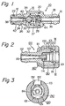
- a plug 10 is made up of a tubular fore piece 14 and a tubular rear piece 18 fixedly coupled, preferably by fusion, to each other by means of a seal ring 20.
- the pieces 14 and 18 are both preferably made of a synthetic resin.
- the fore piece 14 is provided with a nose section 12 to be inserted into a socket when the pipe coupling is assembled. Near the front end, the nose section 12 is externally provided with a seal ring 22, a conical flange 24 and an annular latching groove 26 formed just on the back side of the flange 24.
- the fore piece 14 further internally deffnes an axial fore conduit 38 for the fluid flowing through the pipe coupling.
- the rear piece 18 is provided with a tail section 16 adapted for connection with any suitable hose.
- the rear piece 18 further internally defines an axial rear conduit 36 for the fluid flowing through the pipe coupling, and an intermediate conduit 37 of a larger diameter.
- a valve 30 having a conical head is arranged about the junction between the pieces 14 and 18 with its seal ring 32 in pressure contact with a funnel-shaped seat 34 formed on the internal surface of the fore piece 14. This pressure contact is caused by a helical compression spring 28 interposed between the valve 30 and the rear end of the intermediate conduit 37.
- An axial projection 44 is formed on the rear end of the intermediate conduit 37 in order to limit excessive rearward movement of the valve 30.
- the valve 30 is provided with tubular front extension 42 slidably received in the fore conduit 38 of the fore piece 14. The front extension 42 terminates near the front opening of the fore conduit 38 and, at a position near the conical head of the valve 30, is provided with at least one radial opening 40.
- a socket 100 is made up of a tubular main piece 110, a latching piece 120, a mantle piece 130 and a stop piece 140. These pieces 110 to 140 are all preferably made of a synthetic resin. In particular, at least the main piece 110 should be made of a synthetic resin since it is required to be somewhat resilient as herein after described in more detail.
- the main piece 110 is provided with a front nose section 111 adapted for accommodating the nose section 12 of the plug 10 and a tail section 112 adapted for connection with any hose.
- the nose section 111 is provided, near its periphery, with a tongue 113 projecting forwards, and, near its center, a center projection 114.
- the main piece 110 internally defines an axial conduit 115 which opens in the center projection 114.
- the mantle piece 130 is internally designed so that, when it is inserted over and fixed to the nose section 111 of the main piece 110, an annular groove 131 is left in front of the front end of the nose section 111.
- a radial opening 132 is formed in the wall of the mantle piece 130.
- the latching piece 120 includes a ring section 121 and a tongue 122 extending rearwards from the ring section 121 as best seen in Fig. 4.
- the stop piece 140 is inserted over and fixed to the rear end portion of the nose section 111 of the main piece 110 in order to prevent falling of the mantle piece 130 secured on the main piece 110.
- the tongue 122 of the latching piece 120 rests on the tongue 113 of the main piece 110 so that the latching piece 120 is suspensibly held by the main piece 110.
- the ring section 121 of the latching piece 120 is received partly in the annular groove 131 provided by the mantle piece 130 as shown in Fig. 2.
- the tongue 122 of the latching piece 120 appears in the radial opening 132 of the mantle piece 130 with its outer surface substantially flush with that of the mantle piece 130.
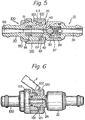
- the ring section 121 of the latching piece 120 is depressed into the annular groove 131 due to pressure abutment with the conical flange 24 of the plug 10 and the tongue 122 of the latching piece 120 sinks in the radial opening 132 of the mantle piece 130 while bending the resilient tongue 113 of the main piece 110. Due to the above-described pressure abutment with the conical flange 24 of the plug 10, the ring section 121 of the latching piece 120 is now fully placed in the annular groove 131 provided by the mantle piece 130 to allow further insertion of the plug 10 into the socket 100.
- the ring section 121 of the latching piece 120 automatically falls into the latching groove 26 of the plug 10 due to spring-back of the resilient tongue 113 which is now released from the pressure contact with the tongue 122 of the latching piece 120. Consequently, the plug 10 and the socket 100 are now firmly assembled together as shown in Fig. 5.
- At least the main piece 110 of the socket 100 is made of a resilient material such as synthetic resin.
- a resilient material such as synthetic resin.
- the known plastic injection moulding may be used for manaufacturing the pipe coupling. This greatly simplifies manufacturing of the pipe coupling whilst naturally causing corresponding lowering in manufacturing cost.
- the latching piece 120 is suspensibly held by the resilient tongue 113 of the socket 100 with its outer surface being substantially flush with that of the socket.
- This flush construction successfully avoids accidental depression of the latching piece 120, i.e. accidental disassembly of the pipe coupling, by application of any unexpected external force.
- the flush construction further provides a simple outer design of the pipe coupling.
- Disassembly of the pipe coupling is carried out utilizing the resilient nature of the tongue 113 of the socket without requirement for provision of any additional spring to that effect. This also contributes to lowering in manufacturing cost.
- the flow rate of the fluid passing through the pipe coupling in the assembled state is determined by the dimension of the annular clearance formed around the conical head of the valve 30 in Fig. 5.
- the dimension of this clearance is fixed once the mechanical design of the pipe coupling is fixed.
- FIG. 7 Another embodiment of the socket shown in Fig. 7 enables adjustment of the flow rate even with the fixed mechanical design of the pipe coupling.
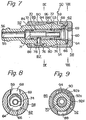
- a socket 50 includes a main piece 52, a mantle piece 58, a latching piece 62, a flow rate adjuster piece 86 and a valve actuating piece 70. At least the main piece 52 and the adjuster piece 86, more preferably all the pieces, are made of a resilient material such as synthetic resin.
- the main piece 52 is provided with a nose section 53 adapted for receiving the nose section 12 of the plug 10, and a tail section 56 adapted for connection with any hose.
- the main piece 52 further internally defined a fore conduit 54 of a large diameter and a rear conduit 55 of a small diameter in axial communication with each other.
- a small flange 84 is formed on the main piece 52 for snap coupling with the adjuster piece 86.
- the nose section 53 is provided with a tongue 69 projecting forwards.
- a guide slot 78 is formed through the wall of the main piece 52, which extends spirally over a prescribed length.
- a flow rate indicator band 98 is disposed to the outer surface of the main piece 52. This indicator band 98 extends in the peripheral direction and includes flow rate indications. One example of such an indication is shown in Fig. 12, in which H designates high flow rate.
- the mantle piece 58 is secured on the nose section 53 of the main piece 52 in an arrangement such that an annular groove 66 is left in front of the fore end of the nose section 53.
- a radial opening 59 is formed in the mantle piece 58 in order to receive the latching piece 62 as hereinafter described in more detail.
- An axial conduit 60 is formed in the mantle piece 58 in communication with the fore conduit 54 of the main piece 52.
- the latching piece 62 includes a ring section 64 received in the annular groove 66 provided by the mantle piece 58, and a tongue 68 extending rearwards and located in the radial opening 59 of the mantle piece 58. Under the condtion shown in the drawing, the tongue 68 of the latching piece 62 rests on the tongue 69 of the main piece 52. In other words, the latching piece 62 is suspensibly supported by the main piece 52 in the mantle piece 58 as shown in Fig. 8. Here, the exposed outer surface of the latching piece 62 is substantially flush with that of the mantle piece 58.
- the flow rate adjuster piece 86 is inserted over the middle section of the main piece 52 and internally defines a guide groove 88 extending in the axial direction.
- a guide pin 82 is inserted into the recess 76 of the actuating piece 70 via the guide slot 78 of the main piece 52 with its head 80 being received in the guide groove 88 of the adjuster piece 86.
- the adjuster piece 86 is designed so that its inner surface is in tight pressure contact with the head 80 of the guide pine 82.
- the guide pin 82 revolves helically about the axis of the main piece 52 due to the helical arrangement of the guide slot 78 and this helical revolution of the guide pin 82 causes axial movement of the actuating piece 70 by means of the engagement of the guide pin 82 with the recess 76 in the pressor piece 70.
- the adjuster piece 86 is further internally provided with a tongue 90 which extends forwards.
- a tongue 90 which extends forwards.
- Axially extending grooves 92a, 92b and so on are formed in the inner surface of the tongue 90 at prescribed, preferably equal, intervals in the periphery direction.
- a projection 94 is formed on the outer surface of the main piece 52, which is adapted for snap engagement with any of the grooves 92a, 92b and so on.
- like grooves may be made in the outer surface of the main piece 52 and a like projection on the inner surface of the tongue 90.
- a radial opening 96 is formed through the adjuster piece 86 so that each flow rate indication is visible from outside. It will be well understood that the interval between adjacent grooves, e.g. 92a and 92b, should be equal to that between the adjacent flow rate indications.
- the socket 50 shown in Fig. 7 is adapted for assembly with the plug 10 shown in Fig. 1.
- the nose section 12 of the plug 10 is inserted into the fore conduit 54 of the socket 50, the conical flange 24 of the plug 10 depresses the ring section 64 of the latching piece 62 into the annular groove 66 provided by the mantle piece 58 and the tongue 69 of the main piece 52 flexes towards the axis of the pipe coupling being pressed by the latching piece 62.
- This procedure is substantially same as that shown in Fig. 6, in which the latching piece 62 is depressed by the finger F.
- the flow rate is set to the highest level and the indication H appears in the radial opening 96 of the adjuster piece 86 as shown in Fig. 12.
- the center projection 74 of the actuating piece 70 is inserted into the fore conduit 38 of the plug 10 and pushes the valve 30 rearwards off the valve seat 34 by means of the front extension 42 while overcoming the repulsion of the compression spring 28. Consequently, a flow passage is established through the pipe coupling, which includes the conduits 36, 37 and 38 of the plug 10, the clearance between the conical head of the valve 30 and the valve seat 34, the axial conduit 71 of the actuating piece 70, and the conduits 54 and 55 of the socket 50.
- the projection 94 on the main piece 52 is in engagement with the groove 92d in the tongue 90 of the adjuster piece 86 and the flow rate is set to naught. Possibly an indication such as "L" may appear in the radical opening 96 in the adjuster piece 86.
- the pressor piece 70 is registered at the rearmost position and, despite the contact between the pressor piece center projection 74 and the valve front extension 42, the valve 30 remains in contact with the valve seat 34. In other words, passage of the fluid through the pipe coupling can be blocked even retaining the assembled state of the pipe coupling.
- the valve is provided with the dual functions, one blocking and opening of the flow passage and the other adjustment of the flow rate.
- Such dual functions are provided by the related mechanism fully encased within the pipe coupling itself. This greatly simplifies and minimizes the construction of the pipe coupling and its related parts in the piping system.
Landscapes
- Engineering & Computer Science (AREA)
- General Engineering & Computer Science (AREA)
- Mechanical Engineering (AREA)
- Quick-Acting Or Multi-Walled Pipe Joints (AREA)
- Joints That Cut Off Fluids, And Hose Joints (AREA)
Claims (14)
Applications Claiming Priority (2)
| Application Number | Priority Date | Filing Date | Title |
|---|---|---|---|
| JP54055388A JPS591912B2 (ja) | 1979-05-04 | 1979-05-04 | 管継手 |
| JP55388/79 | 1979-05-04 |
Publications (2)
| Publication Number | Publication Date |
|---|---|
| EP0018440A1 EP0018440A1 (fr) | 1980-11-12 |
| EP0018440B1 true EP0018440B1 (fr) | 1983-05-18 |
Family
ID=12997117
Family Applications (1)
| Application Number | Title | Priority Date | Filing Date |
|---|---|---|---|
| EP79105336A Expired EP0018440B1 (fr) | 1979-05-04 | 1979-12-21 | Raccord pour tuyaux |
Country Status (6)
| Country | Link |
|---|---|
| US (1) | US4331177A (fr) |
| EP (1) | EP0018440B1 (fr) |
| JP (1) | JPS591912B2 (fr) |
| AU (1) | AU528663B2 (fr) |
| CA (1) | CA1127202A (fr) |
| DE (1) | DE2965478D1 (fr) |
Families Citing this family (42)
| Publication number | Priority date | Publication date | Assignee | Title |
|---|---|---|---|---|
| DE3048223C2 (de) * | 1980-12-20 | 1984-10-31 | Erich Prof.Dr.med. 8520 Erlangen Rügheimer | Konnektions-System für Gas-Leitungen mit ineinandersteckbaren Verbindungselementen für Beatmungs- bzw. Anästhesie-Geräte |
| AU9093182A (en) * | 1981-11-26 | 1983-06-02 | Sabco Ltd. | Quick release hose coupling |
| US4465095A (en) * | 1982-02-16 | 1984-08-14 | Owen, Wickersham & Erickson | Pressure-operated flow control valve and molding method |
| GB2139725B (en) * | 1983-04-27 | 1986-12-31 | Thomas Barnett Saunders | Fluid adapters |
| CH672363A5 (fr) * | 1986-09-29 | 1989-11-15 | Contempo Products | |
| JP2977572B2 (ja) * | 1989-03-13 | 1999-11-15 | コールダー・プロダクツ・カンパニー | 二成形部品からなる雌接続具 |
| JPH0423898U (fr) * | 1990-06-22 | 1992-02-26 | ||
| GB2263322A (en) * | 1992-01-09 | 1993-07-21 | Yeong Duh Lee | Revolvable quick pipe coupling with cut-off valve |
| US5385331A (en) * | 1994-03-15 | 1995-01-31 | Aeroquip Corporation | Valve assembly |
| US20050082828A1 (en) | 2003-09-12 | 2005-04-21 | Wicks Jeffrey C. | Releasable connection assembly for joining tubing sections |
| US8734263B2 (en) * | 2004-04-01 | 2014-05-27 | Qubicaamf Worldwide Llc | Flooring system for bowling alley |
| US7448653B2 (en) | 2005-06-10 | 2008-11-11 | Value Plastics, Inc. | Female connector for releasable coupling with a male connector defining a fluid conduit |
| US7806139B2 (en) | 2006-01-20 | 2010-10-05 | Value Plastics, Inc. | Fluid conduit coupling assembly having male and female couplers with integral valves |
| US20080075528A1 (en) * | 2006-09-22 | 2008-03-27 | Michael Marzetta | Construction system |
| USD654573S1 (en) | 2007-11-19 | 2012-02-21 | Value Plastics, Inc. | Female quick connect fitting |
| JP5090940B2 (ja) * | 2008-01-28 | 2012-12-05 | 株式会社旭製作所 | ワンタッチカプラ |
| USD629894S1 (en) | 2008-07-03 | 2010-12-28 | Value Plastics, Inc. | Male body of connector for fluid tubing |
| USD634840S1 (en) | 2008-07-03 | 2011-03-22 | Value Plastics, Inc. | Female body of connector for fluid tubing |
| USD630320S1 (en) | 2008-07-03 | 2011-01-04 | Value Plastics, Inc. | Connector for fluid tubing |
| US8235426B2 (en) | 2008-07-03 | 2012-08-07 | Nordson Corporation | Latch assembly for joining two conduits |
| HUE029526T2 (en) * | 2008-09-30 | 2017-02-28 | Acticon Ab | Air flow control |
| USD655393S1 (en) | 2009-06-23 | 2012-03-06 | Value Plastics, Inc. | Multi-port valve |
| USD783815S1 (en) | 2009-12-09 | 2017-04-11 | General Electric Company | Male dual lumen bayonet connector |
| USD650478S1 (en) | 2009-12-23 | 2011-12-13 | Value Plastics, Inc. | Female dual lumen connector |
| US10711930B2 (en) | 2009-12-09 | 2020-07-14 | Nordson Corporation | Releasable connection assembly |
| US9388929B2 (en) * | 2009-12-09 | 2016-07-12 | Nordson Corporation | Male bayonet connector |
| USD649240S1 (en) | 2009-12-09 | 2011-11-22 | Value Plastics, Inc. | Male dual lumen bayonet connector |
| CN102753876B (zh) | 2009-12-23 | 2015-07-22 | 诺信公司 | 具有一体式模制悬臂弹簧的按钮闩 |
| EP2516913B1 (fr) | 2009-12-23 | 2014-09-17 | Nordson Corporation | Verrous de raccord de fluide comportant des profils de zones d'entrée |
| USD652511S1 (en) | 2011-02-11 | 2012-01-17 | Value Plastics, Inc. | Female body of connector for fluid tubing |
| USD652510S1 (en) | 2011-02-11 | 2012-01-17 | Value Plastics, Inc. | Connector for fluid tubing |
| USD663022S1 (en) | 2011-02-11 | 2012-07-03 | Nordson Corporation | Male body of connector for fluid tubing |
| USD699840S1 (en) | 2011-07-29 | 2014-02-18 | Nordson Corporation | Male body of connector for fluid tubing |
| USD698440S1 (en) | 2011-07-29 | 2014-01-28 | Nordson Corporation | Connector for fluid tubing |
| USD699841S1 (en) | 2011-07-29 | 2014-02-18 | Nordson Corporation | Female body of connector for fluid tubing |
| USD709612S1 (en) | 2011-12-23 | 2014-07-22 | Nordson Corporation | Female dual lumen connector |
| CN104100788B (zh) * | 2013-04-08 | 2016-08-24 | 富泰华工业(深圳)有限公司 | 接头 |
| US9528644B2 (en) * | 2013-12-12 | 2016-12-27 | Zoje Kitchen & Bath Co. Ltd. | Quick connector assembly |
| JP6249993B2 (ja) * | 2014-06-26 | 2017-12-20 | 日東工器株式会社 | 高圧流体を扱うのに適した雌型継手部材及びそれを備える管継手 |
| USD838366S1 (en) | 2016-10-31 | 2019-01-15 | Nordson Corporation | Blood pressure connector |
| JP2021038763A (ja) * | 2019-08-30 | 2021-03-11 | 一般社団法人 日本消防放水器具工業会 | ノズル内蔵型ホース継手 |
| CA3162713A1 (fr) * | 2019-11-25 | 2021-06-03 | Sprinkler Stop, Llc | Soupape en ligne pour remplacement de tete d'arroseur |
Family Cites Families (10)
| Publication number | Priority date | Publication date | Assignee | Title |
|---|---|---|---|---|
| US2073048A (en) * | 1936-02-15 | 1937-03-09 | Fred I Clark | Selective volume control valve |
| FR1165748A (fr) * | 1957-01-30 | 1958-10-28 | High Pressure Components Ltd | Perfectionnements aux raccords pour tuyaux |
| US3005468A (en) * | 1958-08-13 | 1961-10-24 | Hulsey | Rotary sleeve valves |
| GB1155586A (en) * | 1965-07-08 | 1969-06-18 | Raymond Emile Gromelle | Improved Rapid-Action Hose Connector |
| FR2063800A5 (fr) * | 1969-10-31 | 1971-07-09 | Corobit Anstalt | |
| DE2036215A1 (de) * | 1970-07-21 | 1972-01-27 | Kupex Ag, Glarus (Schweiz) | Rohrleitungssystem |
| US3698742A (en) * | 1970-11-23 | 1972-10-17 | Mc Donnell Douglas Corp | Connector with disconnect warning indicator |
| US4009729A (en) * | 1975-10-20 | 1977-03-01 | Dempco, Inc. | Hydraulic coupler |
| DE2547411B2 (de) * | 1975-10-23 | 1978-04-27 | Armaturenfabrik Hermann Voss, 5290 Wipperfuerth | Schlauch- und/oder Rohrkupplung |
| US4181150A (en) * | 1977-09-12 | 1980-01-01 | Gould, Inc. | Lever-type quick disconnect coupling |
-
1979
- 1979-05-04 JP JP54055388A patent/JPS591912B2/ja not_active Expired
- 1979-12-10 US US06/102,265 patent/US4331177A/en not_active Expired - Lifetime
- 1979-12-11 CA CA341,596A patent/CA1127202A/fr not_active Expired
- 1979-12-12 AU AU53746/79A patent/AU528663B2/en not_active Ceased
- 1979-12-21 DE DE7979105336T patent/DE2965478D1/de not_active Expired
- 1979-12-21 EP EP79105336A patent/EP0018440B1/fr not_active Expired
Also Published As
| Publication number | Publication date |
|---|---|
| DE2965478D1 (en) | 1983-07-07 |
| JPS55149485A (en) | 1980-11-20 |
| US4331177A (en) | 1982-05-25 |
| CA1127202A (fr) | 1982-07-06 |
| AU528663B2 (en) | 1983-05-05 |
| AU5374679A (en) | 1980-11-06 |
| EP0018440A1 (fr) | 1980-11-12 |
| JPS591912B2 (ja) | 1984-01-14 |
Similar Documents
| Publication | Publication Date | Title |
|---|---|---|
| EP0018440B1 (fr) | Raccord pour tuyaux | |
| US5273254A (en) | Fluid conduit quick connectors with anti-spill valves | |
| US4872710A (en) | Releasable quick connect fitting | |
| US6186561B1 (en) | Retainer for piping connector | |
| EP1099895B1 (fr) | Raccord de tuyaux | |
| US4775173A (en) | Hose coupling | |
| US5445358A (en) | Exhaust type quick action coupler | |
| US4275907A (en) | Quick connectable coupling | |
| EP0459016B1 (fr) | Connecteur rapide | |
| JP3366338B2 (ja) | 着脱可能な急速継手 | |
| US4718568A (en) | Fuel filler member for vehicles | |
| US5423515A (en) | Socket of pipe joint | |
| US4828297A (en) | Fluid coupling | |
| AU5299693A (en) | Positive transition quick connect coupling | |
| JPH07151278A (ja) | 波形管用継手 | |
| US20020180210A1 (en) | Releasable plug coupling with protective sleeve | |
| US4216982A (en) | Speed slip-on hose coupler | |
| KR20030066352A (ko) | 2개의 파이프의 탈착 가능한 접속을 위한 신속 연결부 | |
| JPH05115558A (ja) | カテーテル用バルブ装置 | |
| AU675759B2 (en) | A tube joint | |
| US5343892A (en) | Pipe coupling | |
| US4429906A (en) | Female element for quick-coupling connection for flexible pipes | |
| US5305984A (en) | Faucet assembly | |
| US6340180B1 (en) | Releasable coupling assembly for securing a vehicle fuel line | |
| GB2264340A (en) | A plug-in coupling for joining fluid conduits |
Legal Events
| Date | Code | Title | Description |
|---|---|---|---|
| PUAI | Public reference made under article 153(3) epc to a published international application that has entered the european phase |
Free format text: ORIGINAL CODE: 0009012 |
|
| AK | Designated contracting states |
Designated state(s): DE FR GB NL SE |
|
| 17P | Request for examination filed |
Effective date: 19801031 |
|
| GRAA | (expected) grant |
Free format text: ORIGINAL CODE: 0009210 |
|
| AK | Designated contracting states |
Designated state(s): DE FR GB NL SE |
|
| REF | Corresponds to: |
Ref document number: 2965478 Country of ref document: DE Date of ref document: 19830707 |
|
| ET | Fr: translation filed | ||
| PGFP | Annual fee paid to national office [announced via postgrant information from national office to epo] |
Ref country code: SE Payment date: 19830930 Year of fee payment: 5 |
|
| PGFP | Annual fee paid to national office [announced via postgrant information from national office to epo] |
Ref country code: FR Payment date: 19831005 Year of fee payment: 5 |
|
| PGFP | Annual fee paid to national office [announced via postgrant information from national office to epo] |
Ref country code: DE Payment date: 19831123 Year of fee payment: 5 |
|
| PGFP | Annual fee paid to national office [announced via postgrant information from national office to epo] |
Ref country code: NL Payment date: 19831231 Year of fee payment: 5 |
|
| PLBE | No opposition filed within time limit |
Free format text: ORIGINAL CODE: 0009261 |
|
| STAA | Information on the status of an ep patent application or granted ep patent |
Free format text: STATUS: NO OPPOSITION FILED WITHIN TIME LIMIT |
|
| 26N | No opposition filed | ||
| PG25 | Lapsed in a contracting state [announced via postgrant information from national office to epo] |
Ref country code: SE Effective date: 19841222 |
|
| PG25 | Lapsed in a contracting state [announced via postgrant information from national office to epo] |
Ref country code: NL Effective date: 19850701 |
|
| GBPC | Gb: european patent ceased through non-payment of renewal fee | ||
| NLV4 | Nl: lapsed or anulled due to non-payment of the annual fee | ||
| PG25 | Lapsed in a contracting state [announced via postgrant information from national office to epo] |
Ref country code: FR Free format text: LAPSE BECAUSE OF NON-PAYMENT OF DUE FEES Effective date: 19850830 |
|
| PG25 | Lapsed in a contracting state [announced via postgrant information from national office to epo] |
Ref country code: DE Effective date: 19850903 |
|
| REG | Reference to a national code |
Ref country code: FR Ref legal event code: ST |
|
| PG25 | Lapsed in a contracting state [announced via postgrant information from national office to epo] |
Ref country code: GB Effective date: 19881118 |
|
| EUG | Se: european patent has lapsed |
Ref document number: 79105336.6 Effective date: 19851007 |