EP0018574A2 - Embrayage électro-magnétique sans bagues collectrices - Google Patents
Embrayage électro-magnétique sans bagues collectrices Download PDFInfo
- Publication number
- EP0018574A2 EP0018574A2 EP80102147A EP80102147A EP0018574A2 EP 0018574 A2 EP0018574 A2 EP 0018574A2 EP 80102147 A EP80102147 A EP 80102147A EP 80102147 A EP80102147 A EP 80102147A EP 0018574 A2 EP0018574 A2 EP 0018574A2
- Authority
- EP
- European Patent Office
- Prior art keywords
- stator
- rotor
- coupling according
- magnetic coupling
- coil
- Prior art date
- Legal status (The legal status is an assumption and is not a legal conclusion. Google has not performed a legal analysis and makes no representation as to the accuracy of the status listed.)
- Withdrawn
Links
- XEEYBQQBJWHFJM-UHFFFAOYSA-N Iron Chemical compound [Fe] XEEYBQQBJWHFJM-UHFFFAOYSA-N 0.000 claims abstract description 20
- 230000008878 coupling Effects 0.000 claims abstract description 20
- 238000010168 coupling process Methods 0.000 claims abstract description 20
- 238000005859 coupling reaction Methods 0.000 claims abstract description 20
- 230000004907 flux Effects 0.000 claims abstract description 15
- 229910052742 iron Inorganic materials 0.000 claims abstract description 10
- 229910000859 α-Fe Inorganic materials 0.000 claims description 3
- 239000004020 conductor Substances 0.000 claims description 2
- 239000000463 material Substances 0.000 claims description 2
- 230000007797 corrosion Effects 0.000 abstract description 3
- 238000005260 corrosion Methods 0.000 abstract description 3
- 229910001369 Brass Inorganic materials 0.000 description 2
- 239000010951 brass Substances 0.000 description 2
- 238000002347 injection Methods 0.000 description 2
- 239000007924 injection Substances 0.000 description 2
- 238000004519 manufacturing process Methods 0.000 description 2
- 230000000694 effects Effects 0.000 description 1
- 238000005516 engineering process Methods 0.000 description 1
- 230000002349 favourable effect Effects 0.000 description 1
- 239000010687 lubricating oil Substances 0.000 description 1
- 239000002184 metal Substances 0.000 description 1
- 229910052751 metal Inorganic materials 0.000 description 1
- 230000002093 peripheral effect Effects 0.000 description 1
Images
Classifications
-
- F—MECHANICAL ENGINEERING; LIGHTING; HEATING; WEAPONS; BLASTING
- F16—ENGINEERING ELEMENTS AND UNITS; GENERAL MEASURES FOR PRODUCING AND MAINTAINING EFFECTIVE FUNCTIONING OF MACHINES OR INSTALLATIONS; THERMAL INSULATION IN GENERAL
- F16D—COUPLINGS FOR TRANSMITTING ROTATION; CLUTCHES; BRAKES
- F16D27/00—Magnetically- or electrically- actuated clutches; Control or electric circuits therefor
- F16D27/10—Magnetically- or electrically- actuated clutches; Control or electric circuits therefor with an electromagnet not rotating with a clutching member, i.e. without collecting rings
- F16D27/108—Magnetically- or electrically- actuated clutches; Control or electric circuits therefor with an electromagnet not rotating with a clutching member, i.e. without collecting rings with axially movable clutching members
- F16D27/112—Magnetically- or electrically- actuated clutches; Control or electric circuits therefor with an electromagnet not rotating with a clutching member, i.e. without collecting rings with axially movable clutching members with flat friction surfaces, e.g. discs
-
- F—MECHANICAL ENGINEERING; LIGHTING; HEATING; WEAPONS; BLASTING
- F16—ENGINEERING ELEMENTS AND UNITS; GENERAL MEASURES FOR PRODUCING AND MAINTAINING EFFECTIVE FUNCTIONING OF MACHINES OR INSTALLATIONS; THERMAL INSULATION IN GENERAL
- F16D—COUPLINGS FOR TRANSMITTING ROTATION; CLUTCHES; BRAKES
- F16D27/00—Magnetically- or electrically- actuated clutches; Control or electric circuits therefor
- F16D2027/008—Details relating to the magnetic circuit, or to the shape of the clutch parts to achieve a certain magnetic path
Definitions
- the invention relates to an electromagnetic, slip ring-free coupling with a fixed stator carrying the magnetic coil, a rotor connected to a first rotating part and a second rotating part mounted coaxially with the first rotating part and rotatably and longitudinally displaceably connected magnet armature, stator, rotor and Magnetic armatures are arranged and shaped in such a way that the magnetic flux generated by the magnetic coil flows through them in a closed circuit and brings an annular friction surface of the magnet armature into operative connection with the annular friction surface of the rotor due to the resulting attractive forces.
- Such a coupling is, inter alia, the subject of DE-OS 26 28 246. It is the object of the present invention to improve a coupling of this type in such a way that it has high efficiency and great wear resistance with little manufacturing effort and small structural dimensions.
- This is achieved according to the invention in that the stator is mounted in a groove of the rotor which surrounds the stator in a U-shape, in that an annular magnet coil is attached to the stator in that the U-shaped element enclosing the stator and the annular magnet coil
- the parts of the stator and the rotor enclosing the magnetic coil form a conductor of essentially constant cross section for the magnetic flux, and the width of the U-shaped groove.
- This arrangement and shape of the rotor and the stator ensures a very effective magnetic flux around the magnet coil serving to generate the coupling forces with simple means.
- the clutch can transmit relatively high clutch torques with small dimensions and low power consumption.
- the magnetic flux which completely flows through the rotor in the radial direction and only partially in the axial direction can exert only a relatively small axial magnetic force on the stator, so that the power loss which arises on the stator during the switching times of the clutch remains small.
- the magnetic coil plugged onto the stator is wound onto a carrier body injection molded from plastic in a particularly favorable manner in terms of production technology. It is also expedient to inject a fixing lug, which secures the coil against rotation, which engages in a recess in the stator as well as in a recess in the device when the coupling is mounted in the device and thereby fixes the stator in a simple manner on the device.
- annular bearing projection is also formed on the rotor-facing side of the support body mounted on the stator for the magnetic coil, which extends beyond the tubular part of the stator carrying the coil in the axial direction, in that only a part of the The magnetic flux-absorbing part of the stator, which is made of magnetizable material and which carries the magnetic coil, does not lie directly against the rotor, but is supported on the rotor via an attachment of the non-magnetic plastic support body for the magnetic coil, which is between the rotor and stator during the switching times of the Coupling magnetic attraction is further reduced, which further increases the efficiency of the clutch.
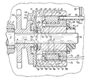
- a fixing pin 14 is inserted, the two ends of which engage in recesses 5 a of a rotor 5 pushed onto the shaft extension 3 a.
- the rotor 5 is made of magnetizable sintered iron to protect it against corrosion and wear. It is held on the shaft extension 3 a by means of a commercially available plastic locking ring 6.
- a stator 7 is mounted, which is surrounded by the groove 5 b in a U-shape.
- a radial flange 7 a is formed, which is shaped so that it closes the U-shaped groove 5 b of the stator 5 to the outside.
- the stator 7 is also dimensioned so that its inner surface 7 b with the inner boundary surface 5 c of the groove 5 b forms a bearing pairing, while the outer boundary surface 7 c of the radial flange 7 a of the stator 7 to the outer boundary surface 5 d of the U-shaped groove 5 b a defined, if possible in the interest of the undisturbed magnetic flux has a small distance.
- the stator 7 is also made of magnetizable sintered iron, in which case the sintered iron is oil-soaked to improve the bearing properties.
- a tubular extension 7 d is also formed on the stator 7, onto which a carrier body 8 made of plastic for a magnetic coil 9 is attached.
- the coil 9 is in one of two radial flanges 8 a and 8 b of the carrier body. formed annulus wound.
- the connecting wires 9 a and 9 b of the coil 9 are guided through a recess 7 e of the rotor 7 to the outside.
- a fixing lug 8 c is injection molded onto the carrier body 8, which projects outwards through a further recess 7 f of the rotor 7 and also engages in a recess 10 a of a part 10 which is fixed to the device. Both the stator 7 and the coil 9 are thereby secured against rotation.
- the axial fixing of the stator 7 towards the outside of the groove 7 b is carried out by an annular edge 6 b of the securing clamping ring 6.
- stator 7 Towards the inside of the U-shaped groove 5 b, the stator 7 is supported by an annular projection 8 d molded onto the carrier body 8. This annular extension 8 e protrudes so far from the tubular part 7 d of the stator 7 that, as will be explained in more detail below, no appreciable magnetic attraction forces can develop in the axial direction between the stator 7 and the rotor 5.
- an attachment 4 a is formed, on which a magnet armature 11, which is stamped from magnetizable sheet metal, is mounted.
- a leaf spring 12 is inserted, which presses the armature 11 against a disc-shaped part 4 b formed on the peripheral part 4.
- the leaf spring 12 is supported on the opposite side against a brass disc 13, which is inserted into an annular recess 5 e of the rotor 5.
- the brass disk 13 is used on the one hand to reduce the sliding friction between the leaf spring 12 and the rotor 5 and on the other hand to prevent the leaf spring 12 from hooking into the recesses 5 a.
- the armature 11 pressed by means of the leaf spring 12 against the radial flange 4b of the circumferential part 4 takes the circumferential one.
- Part 4 by means of a pin 11 b stamped on the armature 11, which engages in a recess 4 c of the flange 4 b.
- a deep, annular groove is formed, which is intended to prevent lubricating oil adhering to the sprocket from spreading over the surface of the rotating part 4 and thereby passing between the effective friction surfaces of the magnetic coupling.
- recesses 5 f are finally formed on it, which extend almost over the entire circumference of the rotor 5 and are interrupted only at individual points by appropriately distributed narrow webs over the circumference. These webs, which are not visible in the drawing, are dimensioned such that their strength is just sufficient to hold together the inner and outer part of the rotor 5, which are separated from one another by the recesses 5 f.
- the effect of the recess 5 f on the magnetic flux can in a known manner by a ring connecting the inner and outer part of the rotor
Landscapes
- Engineering & Computer Science (AREA)
- General Engineering & Computer Science (AREA)
- Physics & Mathematics (AREA)
- Electromagnetism (AREA)
- Mechanical Engineering (AREA)
- Electromagnets (AREA)
- Braking Arrangements (AREA)
Applications Claiming Priority (2)
| Application Number | Priority Date | Filing Date | Title |
|---|---|---|---|
| DE2917548 | 1979-04-30 | ||
| DE19792917548 DE2917548A1 (de) | 1979-04-30 | 1979-04-30 | Elektromagnetische, schleifringlose kupplung |
Publications (2)
| Publication Number | Publication Date |
|---|---|
| EP0018574A2 true EP0018574A2 (fr) | 1980-11-12 |
| EP0018574A3 EP0018574A3 (fr) | 1981-01-07 |
Family
ID=6069663
Family Applications (1)
| Application Number | Title | Priority Date | Filing Date |
|---|---|---|---|
| EP80102147A Withdrawn EP0018574A3 (fr) | 1979-04-30 | 1980-04-22 | Embrayage électro-magnétique sans bagues collectrices |
Country Status (4)
| Country | Link |
|---|---|
| US (1) | US4346616A (fr) |
| EP (1) | EP0018574A3 (fr) |
| CA (1) | CA1152013A (fr) |
| DE (1) | DE2917548A1 (fr) |
Cited By (2)
| Publication number | Priority date | Publication date | Assignee | Title |
|---|---|---|---|---|
| FR2604229A1 (fr) * | 1986-09-19 | 1988-03-25 | Valeo | Dispositif d'embrayage a commande inertielle automatique. |
| DE4226113A1 (de) * | 1992-08-07 | 1994-02-10 | Daimler Benz Ag | Antriebseinheit zur elektrischen Verstellung eines insassenbezogenen Ausrüstungsgegenstandes eines Fahrzeuges |
Families Citing this family (13)
| Publication number | Priority date | Publication date | Assignee | Title |
|---|---|---|---|---|
| JPS60134929U (ja) * | 1984-02-20 | 1985-09-07 | 三菱電機株式会社 | 電磁クラツチ |
| DE3443524C2 (de) * | 1984-11-29 | 1993-12-02 | Stromag Maschf | Wirbelstromkupplung |
| US5123157A (en) * | 1990-04-24 | 1992-06-23 | Tesma International Inc. | Method of making a rotor for an electromagnetic clutch |
| DE19535970A1 (de) * | 1995-01-05 | 1996-07-11 | Dana Corp | Elektromagnetische Reibungskupplung |
| JP3365751B2 (ja) * | 1999-04-02 | 2003-01-14 | 京セラミタ株式会社 | 電磁クラッチ |
| JP3699308B2 (ja) * | 1999-04-02 | 2005-09-28 | 京セラミタ株式会社 | 電磁クラッチ |
| US6578688B2 (en) * | 2001-11-02 | 2003-06-17 | North Coast Clutch Company, Inc. | Spline cushion clutch driver for an electromagnetic clutch |
| JP2004011744A (ja) * | 2002-06-06 | 2004-01-15 | Minebea Co Ltd | 歯形電磁クラッチ・ブレーキ |
| JP4851885B2 (ja) * | 2006-08-22 | 2012-01-11 | 三井金属アクト株式会社 | 開閉体の駆動装置 |
| JP4939877B2 (ja) * | 2006-09-05 | 2012-05-30 | 三井金属アクト株式会社 | 開閉体の駆動装置 |
| US20110036678A1 (en) * | 2007-11-15 | 2011-02-17 | Aisin Seiki Kabushiki Kaisha | Electromagnetic clutch |
| US11428277B2 (en) | 2018-11-21 | 2022-08-30 | Dana Automotive Systems Group, Llc | Joint and clutch assembly |
| EP4253786B1 (fr) * | 2022-03-28 | 2025-07-30 | Warner Electric Europe SAS | Dispositif de freinage électromagnétique configuré pour bloquer un arbre rotatif et système de mobilité comportant le dispositif et l'arbre rotatif |
Family Cites Families (12)
| Publication number | Priority date | Publication date | Assignee | Title |
|---|---|---|---|---|
| US2966975A (en) * | 1955-06-22 | 1961-01-03 | Ite Circuit Breaker Ltd | Electro-magnetic clutch |
| DE1400084A1 (de) * | 1958-08-04 | 1968-11-28 | Ortlinghaus Geb Ohg | Schleifringlose Elektromagnet-Lamellenkupplung |
| FR1230875A (fr) * | 1959-07-21 | 1960-09-20 | Embrayage électro-magnétique à disques sans bague collectrice | |
| FR81088E (fr) * | 1962-02-05 | 1963-07-26 | Transmissions | Dispositif magnétique de transmission de couple |
| US3381784A (en) * | 1966-05-09 | 1968-05-07 | Bendix Corp | Electromagnetic clutch and brake |
| FR1498392A (fr) * | 1966-06-22 | 1967-10-20 | Perfectionnements aux ralentisseurs, aux freins et aux coupleurs à glissement permanent | |
| FR1541888A (fr) * | 1967-10-25 | 1968-10-11 | Bendix Corp | Commande d'accouplement électromagnétique |
| US3530416A (en) * | 1968-12-13 | 1970-09-22 | Warner Electric Brake & Clutch | Magnetic element for stationary field clutches |
| AT290931B (de) * | 1969-03-04 | 1971-06-25 | Haeussermann Gmbh Lamellen Und | Schleifringlose Einscheiben - Elektromagnetkupplung |
| JPS537570B1 (fr) * | 1970-01-30 | 1978-03-18 | ||
| US3854562A (en) * | 1973-08-15 | 1974-12-17 | Victor Comptometer Corp | Electromagnetic clutch |
| US3876048A (en) * | 1974-02-11 | 1975-04-08 | Gen Motors Corp | Electromagnetic clutch |
-
1979
- 1979-04-30 DE DE19792917548 patent/DE2917548A1/de not_active Ceased
-
1980
- 1980-04-22 EP EP80102147A patent/EP0018574A3/fr not_active Withdrawn
- 1980-04-23 CA CA000350457A patent/CA1152013A/fr not_active Expired
- 1980-04-24 US US06/143,304 patent/US4346616A/en not_active Expired - Lifetime
Cited By (2)
| Publication number | Priority date | Publication date | Assignee | Title |
|---|---|---|---|---|
| FR2604229A1 (fr) * | 1986-09-19 | 1988-03-25 | Valeo | Dispositif d'embrayage a commande inertielle automatique. |
| DE4226113A1 (de) * | 1992-08-07 | 1994-02-10 | Daimler Benz Ag | Antriebseinheit zur elektrischen Verstellung eines insassenbezogenen Ausrüstungsgegenstandes eines Fahrzeuges |
Also Published As
| Publication number | Publication date |
|---|---|
| CA1152013A (fr) | 1983-08-16 |
| EP0018574A3 (fr) | 1981-01-07 |
| DE2917548A1 (de) | 1980-11-06 |
| US4346616A (en) | 1982-08-31 |
Similar Documents
| Publication | Publication Date | Title |
|---|---|---|
| EP0018574A2 (fr) | Embrayage électro-magnétique sans bagues collectrices | |
| DE2418367C2 (de) | Elektromagnetische Federwickelkupplung | |
| DE4117681C2 (fr) | ||
| DE102004054397B4 (de) | Elektromagnetisches Stellglied | |
| DE19751766A1 (de) | Koaxialer Motorstarter | |
| DE69024233T2 (de) | Elektromagnetisch betätigter Federkupplungsmechanismus | |
| DE7930916U1 (de) | Kollektorloser gleichstrommotor | |
| DE8435225U1 (de) | Elektromagnetische Kupplung | |
| DE3110282C2 (de) | Schrittschaltmotor | |
| DE2755887A1 (de) | Abgedichtete elektromagnetische kupplung fuer textilmaschinen | |
| DE69002307T2 (de) | Elektromagnetische Kupplungsvorrichtung. | |
| DE1020242B (de) | Reibungskupplung, insbesondere fuer Kraftfahrzeuge | |
| DE1944721C3 (de) | Schubtrieb-Anlassvorrichtung für Brennkraftmaschinen | |
| DE3149916A1 (de) | Magnetpol-aufbau fuer ein elektromagnetisches ventil, vorzugsweise brennstoff-einspritzventil | |
| DE2736705A1 (de) | Getriebemotor | |
| DE4317977C2 (de) | Koaxialer Anlasser | |
| DE69506358T2 (de) | Kommutatorelektrische Maschine, insbesondere Gleichstromelektromotor | |
| DE2307551C3 (de) | Elektromagnetisch betätigte Zahnkupplung | |
| DE2821824B2 (de) | Feldmagnet | |
| DE69304836T2 (de) | Synchronmotor | |
| DE1600068B1 (de) | Schleifringlose elektromagnetisch betaetigte Lamellenkupplung | |
| DE3513494C2 (de) | Magnetbremse | |
| DE69112050T2 (de) | Rotorkonstruktion in elektromagnetischer kupplung. | |
| EP0786852B1 (fr) | Entraínement électrique | |
| EP0142211B1 (fr) | Moteur électrique avec un dispositif d'amortissement |
Legal Events
| Date | Code | Title | Description |
|---|---|---|---|
| PUAI | Public reference made under article 153(3) epc to a published international application that has entered the european phase |
Free format text: ORIGINAL CODE: 0009012 |
|
| PUAL | Search report despatched |
Free format text: ORIGINAL CODE: 0009013 |
|
| AK | Designated contracting states |
Designated state(s): BE CH FR GB |
|
| AK | Designated contracting states |
Designated state(s): BE CH FR GB |
|
| 17P | Request for examination filed |
Effective date: 19801205 |
|
| STAA | Information on the status of an ep patent application or granted ep patent |
Free format text: STATUS: THE APPLICATION IS DEEMED TO BE WITHDRAWN |
|
| 18D | Application deemed to be withdrawn |
Effective date: 19821116 |
|
| RIN1 | Information on inventor provided before grant (corrected) |
Inventor name: PUSTKA, KAREL Inventor name: BROENNER, HERMANN Inventor name: VONDROWSKI, GABRIEL Inventor name: MUELLRITTER, LUDWIG Inventor name: GEISSLINGER, WOLFGANG |