EP0018657A1 - Equerre pour diviser des angles et tracer des parallèles - Google Patents
Equerre pour diviser des angles et tracer des parallèles Download PDFInfo
- Publication number
- EP0018657A1 EP0018657A1 EP80102407A EP80102407A EP0018657A1 EP 0018657 A1 EP0018657 A1 EP 0018657A1 EP 80102407 A EP80102407 A EP 80102407A EP 80102407 A EP80102407 A EP 80102407A EP 0018657 A1 EP0018657 A1 EP 0018657A1
- Authority
- EP
- European Patent Office
- Prior art keywords
- leg
- frame
- angle
- parallel
- stop
- Prior art date
- Legal status (The legal status is an assumption and is not a legal conclusion. Google has not performed a legal analysis and makes no representation as to the accuracy of the status listed.)
- Granted
Links
- 239000000969 carrier Substances 0.000 description 4
- 230000001788 irregular Effects 0.000 description 3
- 238000006073 displacement reaction Methods 0.000 description 2
- 238000004519 manufacturing process Methods 0.000 description 2
- 244000131360 Morinda citrifolia Species 0.000 description 1
- 238000010276 construction Methods 0.000 description 1
- 239000003550 marker Substances 0.000 description 1
- 235000017524 noni Nutrition 0.000 description 1
- 210000002435 tendon Anatomy 0.000 description 1
Images

Classifications
-
- B—PERFORMING OPERATIONS; TRANSPORTING
- B43—WRITING OR DRAWING IMPLEMENTS; BUREAU ACCESSORIES
- B43L—ARTICLES FOR WRITING OR DRAWING UPON; WRITING OR DRAWING AIDS; ACCESSORIES FOR WRITING OR DRAWING
- B43L7/00—Straightedges
- B43L7/10—Plural straightedges relatively movable
-
- B—PERFORMING OPERATIONS; TRANSPORTING
- B43—WRITING OR DRAWING IMPLEMENTS; BUREAU ACCESSORIES
- B43L—ARTICLES FOR WRITING OR DRAWING UPON; WRITING OR DRAWING AIDS; ACCESSORIES FOR WRITING OR DRAWING
- B43L13/00—Drawing instruments, or writing or drawing appliances or accessories not otherwise provided for
Definitions
- the present invention relates to a dividing and parallel drawing angle, consisting of two abutment legs enclosing a right angle, connected at one end to one another, and a holding leg fastened between them in their cutting area, one longitudinal edge of which is the bisector of the included right angle.
- This centering angle is already known as a so-called centering angle.
- This centering angle is applied to the circumference of a circular area with both contact legs, so that the center point of the circular area can be torn by means of the central leg.
- this known centering angle it is not possible to make arbitrary circular divisions on the round body and to draw or record any polygons, be they regular or irregular, on the surface of the round body.
- a dividing apparatus, a parallel height marker and a marking plate have been used so far, but their joint handling is relatively difficult and time-consuming.
- these three parts are bulky and difficult to transport. They also require considerable manufacturing costs.
- the object of the present invention is to improve an angle device according to the prior art in such a way that any division and any polygon can be easily and quickly marked on the circular surface of a round body.
- the angle device according to the invention should also be distinguished by a relatively low weight and low production costs.
- a right-angled angular frame with a frame leg is arranged to be longitudinally displaceable and a stop is slidably attached to this frame leg, the stop surface of which is perpendicular to the longitudinal edge of the angle leg forming the bisector, and the two angular frame legs a leg describing at least one quarter-circle arc is assigned at the end.
- the two frame members are formed of equal length and both ends thereof are connected to each other through the quarter- "i arcuate legs. It may also be according to the invention advantageous if slidably disposed on the quarter circular arc shaped legs perpendicularly thereto, a degree pointer.
- the radius of the workpiece to be marked is set on the leg of the angular frame parallel to the middle leg, and the angular frame is then displaced with this adjusted stop until it abuts the workpiece with the stop Center of the workpiece, so that it can be easily marked, and with the help of one on the degree scale on the quarter-circle arm and two nonies on the degree indicator, any angle on the quarter-circle leg of the angle frame adjusted and marked on the workpiece.
- the angle set in each case can be added by rotating the entire angle device and thus any division and any polygon be scribed on the workpiece.
- the parallel bar provided according to the invention serves to mark squares or rectangles or to connect the intersections of polygons, be they regular, irregular or also to mark tendons and the like.
- a centering and dividing angle is accordingly created; which is an easy-to-use tool in terms of its construction and, above all, its weight, and which can be used on the go, d. H. it can be used and used quickly anywhere.
- This is particularly advantageous, for example, in the case of workpieces which are themselves not transportable, either because of their weight or because they are firmly connected to other components.
- a centering and dividing angle consists of two contact legs 1, 2 enclosing a right angle and connected at one end to one another. Between the contact legs 1, 2 at their intersection, a central leg 3 is fastened, one longitudinal edge 4 of which bisects the angle bisector of the one enclosed by the contact legs The entire centering and dividing angle is stiffened by means of a cross bar 6, which is connected to the one contact leg 1 and the middle leg 3.
- a handle 7 is formed with which the centering and pitch angle can be handled.
- the handle 7 can be made of plastic, for example, and is fastened, for example, by screws to the outside of the contact leg. As can further be seen from FIG.
- an angled frame 8 enclosing a right angle and having a frame leg 9 is arranged to be longitudinally displaceable on the middle leg 3.
- the middle leg 3 has, for example at its two ends, transverse webs 11 which laterally enclose the middle leg with their web ends and are advantageously held in grooves in the middle leg in the form of a dovetail-shaped guide.
- a grip part 11a is provided with a locking screw 12. hen with which the position of the entire angular frame on the center leg 3 can be fixed in the desired position.
- the free ends of the frame legs 9, 10 of the angular frame 8 are connected at the ends to one another by an arcuate leg 14, which in the example shown is in the form of a quarter circle.
- a degree pointer 16 is displaceably arranged on the arcuate leg 14 by means of a guide part 17. With a locking screw 18, the degree pointer can be fixed in any position on the curved leg 14. For easier handling of the guide part on the outside of a handle 19, preferably made of plastic.
- a stop body 21 is slidably arranged on the frame leg 9 of the angle frame 8 parallel to the center leg 3. This stop body 21 consists of a guide part 22 and a stop section 23 perpendicular to the guide part. The stop section 23 is advantageously detachably fastened to the guide part 22.
- the guide member 22 is guided on the frame leg 9 in the same longitudinal guide grooves.
- the stop body 21 can be fixed in any position on the frame leg 9 of the angular frame.
- the entire angular frame can then be moved in the longitudinal direction together with the stop body on the middle leg 3.
- the centering and dividing angle according to the invention also has a parallel bar 26.
- This parallel bar is displaceably arranged at one end by means of a guide part 27 on the contact leg 2.
- the guide part 27 is guided on the contact leg 2 in a manner known per se by means of T-shaped guide grooves into which projections formed on the guide part 27 engage.
- the guide part 27 can be fixed on the contact leg 2 by means of a locking screw 28.
- the contact leg 2, which serves to guide the parallel bar 26 is expediently longer than the contact leg 1.
- a handle 29 is formed on the guide part , advantageously made of plastic, with which an easier handling of the guide part is achieved.
- the individual parts of the invention different scales according to the centering and pitch angle.
- a continuous scale 31 is provided on the middle leg, this scale 31 has a millimeter graduation.
- the two frame legs 9, 10 have. likewise scales 32, 33, which expediently have a millimeter graduation.
- the scales 32, 33 are arranged on the frame legs such that the longitudinal edge 4 of the middle leg coincides with the start of the scale 32 and the inner edge 34 of the frame leg 10 coincides with the start of the scale 33.
- On the parallel bar 26 there is preferably also a scale 35 provided that has a millimeter division.
- the contact leg 2 also has a scale. If the guide part 27 is shifted on the scale by 10 mm, the guide part 27 covers a distance of 14.14 mm on the contact leg 2, the distance between the middle leg 3 and the parallel bar 26 changing only by 10 mm.
- the operation of the centering and dividing angle according to the invention shown in FIG. 1 is now as follows: First, the radius of a workpiece 38 to be machined, which is shown in broken lines, is set with the stop body 21 on the scale 33 of the frame leg 9, and by means of the locking screw 24, the stop body 21 is clamped in a vibration-proof manner. The entire angular frame 8 is then moved with its stop section 23 to the workpiece up to the stop of the stop body 21 and also fixed in a vibration-resistant manner with the locking screw 12. The centering and dividing angle according to the invention is thus also fixed to and includes the workpiece 38 to be marked, but it can easily be rotated 360 ° and more around the workpiece.
- the degree pointer 16 is now aligned tet and points exactly to the center of the workpiece 38, which can be easily torn with it.
- any angle can be set and torn on the workpiece with a scriber.
- the edge 34 of the frame leg 10 forms the second center line to the workpiece at an angle of 90 ° to the longitudinal edge 4, the angle set with the degree pointer can be added as often as desired by rotating the entire angle and thus any division and any polygon on the Workpiece to be scribed.
- the parallel bar 26 is used to mark squares or rectangles or to connect the intersections of polygons, be they regular or irregular or to mark chords, secants and tangents or the like.
- the used distance between the parallel bar and the middle leg is set on the scale of the system leg 2 with the guide part 27. Then the parallel bar is fixed vibration-proof with the locking screw, and now the desired line on the workpiece can be marked, for example with the help of a scriber.
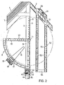
- the embodiment shown therein differs from that according to FIG. 1 in that on the one hand the adjustment of the angle frame via the handle part 11a and on the other hand the parallel bar are designed differently.
- an adjusting body 42 is used, which acts on the handle part 41 of the angle frame 8 by means of an adjusting pin 43.
- the distance between the two parts 41, 42 can be adjusted via the pin 43 by means of an adjusting wheel 44.
- Both parts can be fixed by means of locking screws 45, 46.
- Another difference is in the design of the parallel bar 50.
- this consists of two scale carriers 52 formed parallel to one another on a guide part 51.
- the scale carriers 52 are connected at their free ends via a web 54 for reasons of stability.
- This embodiment has the advantage that, due to the fixed distance between the two scale carriers 52, several parallel lines can be drawn simultaneously.
- the scale present on the scale carriers 52 is expediently again a millimeter scale 55.
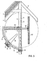
- FIG. 3 shows a further embodiment of a centering and dividing angle according to the invention.
- the same parts as in FIGS. 1 and 2 are provided with the same reference numbers.
- the main difference from the embodiment according to FIG. 1 is the different guidance of the parallel bar 60.
- This parallel bar 60 is slidably attached to a bar 61 running perpendicular to it, which is slidably guided on the frame leg 10 of the angular frame 8 perpendicular to the middle leg 3 .
- the frame leg 10 has a guide part 62 fastened to it, in which the vertical bar 61 is dovetailed in grooves.
- the vertical bar 61 expediently has a scale so that an easy adjustment of the distance to the middle leg 3 is possible.
- the design of the handle part 63 is concerned, this corresponds in the form shown to the handle part 11 a according to FIG. 1.
Landscapes
- Length-Measuring Instruments Using Mechanical Means (AREA)
- Drawing Aids And Blackboards (AREA)
- A Measuring Device Byusing Mechanical Method (AREA)
- Electrical Discharge Machining, Electrochemical Machining, And Combined Machining (AREA)
- Diaphragms For Electromechanical Transducers (AREA)
- Liquid Crystal Substances (AREA)
- Pit Excavations, Shoring, Fill Or Stabilisation Of Slopes (AREA)
- Measurement And Recording Of Electrical Phenomena And Electrical Characteristics Of The Living Body (AREA)
- Signal Processing For Digital Recording And Reproducing (AREA)
Priority Applications (1)
| Application Number | Priority Date | Filing Date | Title |
|---|---|---|---|
| AT80102407T ATE2607T1 (de) | 1979-05-07 | 1980-05-03 | Teilungs- und parallelzeichnungswinkel. |
Applications Claiming Priority (2)
| Application Number | Priority Date | Filing Date | Title |
|---|---|---|---|
| DE2918321A DE2918321C2 (de) | 1979-05-07 | 1979-05-07 | Teilungs- und Parallelzeichnungswinkel |
| DE2918321 | 1979-05-07 |
Publications (2)
| Publication Number | Publication Date |
|---|---|
| EP0018657A1 true EP0018657A1 (fr) | 1980-11-12 |
| EP0018657B1 EP0018657B1 (fr) | 1983-02-23 |
Family
ID=6070104
Family Applications (1)
| Application Number | Title | Priority Date | Filing Date |
|---|---|---|---|
| EP80102407A Expired EP0018657B1 (fr) | 1979-05-07 | 1980-05-03 | Equerre pour diviser des angles et tracer des parallèles |
Country Status (7)
| Country | Link |
|---|---|
| US (1) | US4352247A (fr) |
| EP (1) | EP0018657B1 (fr) |
| JP (1) | JPS5819480B2 (fr) |
| AT (1) | ATE2607T1 (fr) |
| DE (1) | DE2918321C2 (fr) |
| DK (1) | DK149361C (fr) |
| ES (1) | ES491258A0 (fr) |
Cited By (3)
| Publication number | Priority date | Publication date | Assignee | Title |
|---|---|---|---|---|
| CN102514423A (zh) * | 2012-01-04 | 2012-06-27 | 贵州开磷(集团)有限责任公司 | 一种三心拱喷绘器 |
| CN103895327A (zh) * | 2014-03-31 | 2014-07-02 | 珠海康德莱医疗器械有限公司 | 一种丝印网版的定位制作装置及方法 |
| CN104494341A (zh) * | 2014-12-11 | 2015-04-08 | 浙江工业大学 | 光感智能任意角等分仪 |
Families Citing this family (15)
| Publication number | Priority date | Publication date | Assignee | Title |
|---|---|---|---|---|
| JPS60190394A (ja) * | 1984-03-05 | 1985-09-27 | 劉 保伸 | 万能分度器 |
| JPS61206280U (fr) * | 1985-06-14 | 1986-12-26 | ||
| US4653194A (en) * | 1985-10-18 | 1987-03-31 | Kim Yoon H | Composite-type ruler |
| JPH086564Y2 (ja) * | 1991-05-24 | 1996-02-28 | 清三 伊藤 | 重量物運搬用キャスター |
| US6272758B1 (en) * | 1999-07-26 | 2001-08-14 | Gene R. Wheeler | Steel worker's layout tool |
| US6581294B2 (en) | 2001-11-03 | 2003-06-24 | Livio Svaldi | Angle finder for large ducts |
| US6694633B1 (en) * | 2002-08-16 | 2004-02-24 | Shelby M. Nyquist | Common rafter and hip layout tool |
| WO2006031682A2 (fr) * | 2004-09-14 | 2006-03-23 | Hembree Wayne A | Transformateur de coordonnees gps |
| US20090025238A1 (en) * | 2007-07-26 | 2009-01-29 | Bowman James L | Construction tool for installing stairway components |
| US8881416B2 (en) * | 2008-05-02 | 2014-11-11 | John Menendez | Assembly and method for taping walls for painting stripes and patterns |
| DE102013201875B4 (de) * | 2013-02-05 | 2015-08-06 | Mario Neugärtner | Verfahren zur Ermittlung des Mittelpunktes und Gliedermaßstab zur Durchführung des Verfahrens |
| CN107856448A (zh) * | 2017-10-31 | 2018-03-30 | 昆明理工大学 | 一种集成的平面设计绘图工具尺 |
| CN111845163A (zh) * | 2019-04-28 | 2020-10-30 | 上海鹰毅建筑规划有限公司 | 一种可扩展的建筑设计用画图装置 |
| US11293741B2 (en) * | 2019-08-09 | 2022-04-05 | The Boeing Company | Sizing tool |
| CN115247989A (zh) * | 2022-01-27 | 2022-10-28 | 浙江省德清县职业中等专业学校 | 一种可测圆心的多功能尺 |
Citations (1)
| Publication number | Priority date | Publication date | Assignee | Title |
|---|---|---|---|---|
| US2348878A (en) * | 1943-04-23 | 1944-05-16 | Ralph Ashton | Center locating device |
Family Cites Families (6)
| Publication number | Priority date | Publication date | Assignee | Title |
|---|---|---|---|---|
| US535223A (en) * | 1895-03-05 | Measuring and drawing instrument | ||
| DE195050C (fr) * | ||||
| DE468102C (de) * | 1928-11-06 | Emil Rudolph | Winkelmesser | |
| DE633637C (de) | 1936-07-31 | Albert Rotach | Winkelmesser | |
| US1893973A (en) * | 1932-07-01 | 1933-01-10 | Yavicoli Felix | Mechanic's tool |
| JPS5360800A (en) * | 1976-11-11 | 1978-05-31 | Toshiya Suzuki | Markinggoff instrument for centering of ctrcle |
-
1979
- 1979-05-07 DE DE2918321A patent/DE2918321C2/de not_active Expired
-
1980
- 1980-04-24 US US06/143,443 patent/US4352247A/en not_active Expired - Lifetime
- 1980-05-03 AT AT80102407T patent/ATE2607T1/de not_active IP Right Cessation
- 1980-05-03 EP EP80102407A patent/EP0018657B1/fr not_active Expired
- 1980-05-07 ES ES491258A patent/ES491258A0/es active Granted
- 1980-05-07 DK DK199480A patent/DK149361C/da not_active IP Right Cessation
- 1980-05-07 JP JP55059545A patent/JPS5819480B2/ja not_active Expired
Patent Citations (1)
| Publication number | Priority date | Publication date | Assignee | Title |
|---|---|---|---|---|
| US2348878A (en) * | 1943-04-23 | 1944-05-16 | Ralph Ashton | Center locating device |
Cited By (5)
| Publication number | Priority date | Publication date | Assignee | Title |
|---|---|---|---|---|
| CN102514423A (zh) * | 2012-01-04 | 2012-06-27 | 贵州开磷(集团)有限责任公司 | 一种三心拱喷绘器 |
| CN102514423B (zh) * | 2012-01-04 | 2014-07-09 | 贵州开磷(集团)有限责任公司 | 一种三心拱喷绘器 |
| CN103895327A (zh) * | 2014-03-31 | 2014-07-02 | 珠海康德莱医疗器械有限公司 | 一种丝印网版的定位制作装置及方法 |
| CN104494341A (zh) * | 2014-12-11 | 2015-04-08 | 浙江工业大学 | 光感智能任意角等分仪 |
| CN104494341B (zh) * | 2014-12-11 | 2016-04-13 | 浙江工业大学 | 光感智能任意角等分仪 |
Also Published As
| Publication number | Publication date |
|---|---|
| DE2918321C2 (de) | 1982-03-11 |
| DK199480A (da) | 1980-11-08 |
| DK149361B (da) | 1986-05-20 |
| ES8100780A1 (es) | 1980-12-01 |
| DK149361C (da) | 1986-11-03 |
| US4352247A (en) | 1982-10-05 |
| ES491258A0 (es) | 1980-12-01 |
| ATE2607T1 (de) | 1983-03-15 |
| JPS5624199A (en) | 1981-03-07 |
| DE2918321A1 (de) | 1980-11-13 |
| EP0018657B1 (fr) | 1983-02-23 |
| JPS5819480B2 (ja) | 1983-04-18 |
Similar Documents
| Publication | Publication Date | Title |
|---|---|---|
| EP0018657B1 (fr) | Equerre pour diviser des angles et tracer des parallèles | |
| EP0149429B1 (fr) | Dispositif pour maintenir une pièce dans une position spatiale désirée | |
| EP0315728B1 (fr) | Dispositif pour la coupe de carreaux | |
| DE3534223C2 (de) | Anschlagwinkel zum Anreißen von Dachsparren-Schnitten | |
| DE2633285C2 (de) | Halterung für das Justieren einer als Vorlage in einer Kopiermaschine zu verwendenden Brillenfassung | |
| DE3727857A1 (de) | Lineare magnetische skaleneinheit | |
| DE3714336C1 (de) | Winkelschraubstock | |
| DE3626588C1 (en) | Measuring compass | |
| WO1999046561A1 (fr) | Niveau a bulle d'air | |
| DE2034571A1 (de) | Winkelmeßgerat | |
| EP1125692B1 (fr) | Equerre à rapporteur et talon | |
| DE7913088U1 (de) | Teilungs- und parallelzeichnungswinkel | |
| DE3407532C2 (de) | Feinmeßgerät | |
| DE3120644C2 (de) | Justiereinrichtung für eine Magnetsonde | |
| DE2462276C3 (de) | Gerät zum Messen der Höhe eines auf einer Unterlage stehenden Gegenstandes oder zum Anreißen eines solchen Gegenstandes in einer vorgegebenen Höhe | |
| DE3630616C2 (fr) | ||
| DE3108251A1 (de) | Vorrichtung zum lagegenauen ausrichten eines werkstueckes in zwei koordinatenachsen bezueglich wenigstens eines werkzeugs einer werkzeugmaschine | |
| DE4004486C2 (fr) | ||
| EP0160264A1 (fr) | Outil de marquage | |
| DE616035C (de) | Anreisslehrengeraet | |
| DE3430378A1 (de) | Zeichengeraet | |
| DE1798419C (de) | Aufnahmekopf fur Meß- und Anreiß werk zeuge Ausscheidung aus 1773282 | |
| DE3125818C2 (de) | Anreißschieblehre | |
| DE689047C (de) | Verfahren zur Festlegung der Umrissformen von Bauteilen | |
| DE102022003506A1 (de) | Lehre zum Einstellen und Übertragen von Winkeln oder Längen |
Legal Events
| Date | Code | Title | Description |
|---|---|---|---|
| PUAI | Public reference made under article 153(3) epc to a published international application that has entered the european phase |
Free format text: ORIGINAL CODE: 0009012 |
|
| AK | Designated contracting states |
Designated state(s): AT BE CH FR GB IT LU NL SE |
|
| 17P | Request for examination filed |
Effective date: 19810406 |
|
| ITF | It: translation for a ep patent filed | ||
| GRAA | (expected) grant |
Free format text: ORIGINAL CODE: 0009210 |
|
| AK | Designated contracting states |
Designated state(s): AT BE CH FR GB IT LI LU NL SE |
|
| REF | Corresponds to: |
Ref document number: 2607 Country of ref document: AT Date of ref document: 19830315 Kind code of ref document: T |
|
| ET | Fr: translation filed | ||
| ITTA | It: last paid annual fee | ||
| PGFP | Annual fee paid to national office [announced via postgrant information from national office to epo] |
Ref country code: NL Payment date: 19900531 Year of fee payment: 11 |
|
| PGFP | Annual fee paid to national office [announced via postgrant information from national office to epo] |
Ref country code: GB Payment date: 19910503 Year of fee payment: 12 |
|
| PGFP | Annual fee paid to national office [announced via postgrant information from national office to epo] |
Ref country code: AT Payment date: 19910531 Year of fee payment: 12 |
|
| PGFP | Annual fee paid to national office [announced via postgrant information from national office to epo] |
Ref country code: CH Payment date: 19910621 Year of fee payment: 12 |
|
| PG25 | Lapsed in a contracting state [announced via postgrant information from national office to epo] |
Ref country code: NL Effective date: 19911201 |
|
| NLV4 | Nl: lapsed or anulled due to non-payment of the annual fee | ||
| PGFP | Annual fee paid to national office [announced via postgrant information from national office to epo] |
Ref country code: LU Payment date: 19920416 Year of fee payment: 13 |
|
| PG25 | Lapsed in a contracting state [announced via postgrant information from national office to epo] |
Ref country code: GB Effective date: 19920503 Ref country code: AT Effective date: 19920503 |
|
| PG25 | Lapsed in a contracting state [announced via postgrant information from national office to epo] |
Ref country code: LI Effective date: 19920531 Ref country code: CH Effective date: 19920531 |
|
| EPTA | Lu: last paid annual fee | ||
| PGFP | Annual fee paid to national office [announced via postgrant information from national office to epo] |
Ref country code: SE Payment date: 19921029 Year of fee payment: 13 |
|
| PGFP | Annual fee paid to national office [announced via postgrant information from national office to epo] |
Ref country code: FR Payment date: 19921130 Year of fee payment: 13 Ref country code: BE Payment date: 19921130 Year of fee payment: 13 |
|
| GBPC | Gb: european patent ceased through non-payment of renewal fee |
Effective date: 19920503 |
|
| REG | Reference to a national code |
Ref country code: CH Ref legal event code: PL |
|
| PG25 | Lapsed in a contracting state [announced via postgrant information from national office to epo] |
Ref country code: LU Free format text: LAPSE BECAUSE OF NON-PAYMENT OF DUE FEES Effective date: 19930503 |
|
| PG25 | Lapsed in a contracting state [announced via postgrant information from national office to epo] |
Ref country code: SE Effective date: 19930504 |
|
| PG25 | Lapsed in a contracting state [announced via postgrant information from national office to epo] |
Ref country code: BE Effective date: 19930531 |
|
| BERE | Be: lapsed |
Owner name: ROHDE NORBERT-JOSEF Effective date: 19930531 |
|
| PG25 | Lapsed in a contracting state [announced via postgrant information from national office to epo] |
Ref country code: FR Effective date: 19940131 |
|
| REG | Reference to a national code |
Ref country code: FR Ref legal event code: ST |
|
| EUG | Se: european patent has lapsed |
Ref document number: 80102407.6 Effective date: 19931210 |
|
| PLBE | No opposition filed within time limit |
Free format text: ORIGINAL CODE: 0009261 |
|
| STAA | Information on the status of an ep patent application or granted ep patent |
Free format text: STATUS: NO OPPOSITION FILED WITHIN TIME LIMIT |