EP0018921A1 - Vorrichtung zur elektrischen Übertragung durch ein System lösbarer und kontaktloser Verbindungen - Google Patents
Vorrichtung zur elektrischen Übertragung durch ein System lösbarer und kontaktloser Verbindungen Download PDFInfo
- Publication number
- EP0018921A1 EP0018921A1 EP80400614A EP80400614A EP0018921A1 EP 0018921 A1 EP0018921 A1 EP 0018921A1 EP 80400614 A EP80400614 A EP 80400614A EP 80400614 A EP80400614 A EP 80400614A EP 0018921 A1 EP0018921 A1 EP 0018921A1
- Authority
- EP
- European Patent Office
- Prior art keywords
- wall
- turn
- clamp
- transformer
- disposed
- Prior art date
- Legal status (The legal status is an assumption and is not a legal conclusion. Google has not performed a legal analysis and makes no representation as to the accuracy of the status listed.)
- Granted
Links
- 230000005540 biological transmission Effects 0.000 title claims abstract description 18
- 238000004804 winding Methods 0.000 claims description 15
- 238000000034 method Methods 0.000 claims description 6
- 238000005096 rolling process Methods 0.000 claims description 2
- 210000004027 cell Anatomy 0.000 description 35
- 238000005259 measurement Methods 0.000 description 7
- RYGMFSIKBFXOCR-UHFFFAOYSA-N Copper Chemical compound [Cu] RYGMFSIKBFXOCR-UHFFFAOYSA-N 0.000 description 3
- 229910052802 copper Inorganic materials 0.000 description 3
- 239000010949 copper Substances 0.000 description 3
- 238000010891 electric arc Methods 0.000 description 3
- 238000005260 corrosion Methods 0.000 description 2
- 230000007797 corrosion Effects 0.000 description 2
- 230000004907 flux Effects 0.000 description 2
- 229910001220 stainless steel Inorganic materials 0.000 description 2
- 239000010935 stainless steel Substances 0.000 description 2
- 238000003466 welding Methods 0.000 description 2
- 210000002421 cell wall Anatomy 0.000 description 1
- 238000004891 communication Methods 0.000 description 1
- 238000001514 detection method Methods 0.000 description 1
- 238000006073 displacement reaction Methods 0.000 description 1
- 230000000694 effects Effects 0.000 description 1
- 230000008030 elimination Effects 0.000 description 1
- 238000003379 elimination reaction Methods 0.000 description 1
- 238000004880 explosion Methods 0.000 description 1
- 239000002360 explosive Substances 0.000 description 1
- 238000009413 insulation Methods 0.000 description 1
- 238000002955 isolation Methods 0.000 description 1
- 239000007788 liquid Substances 0.000 description 1
- 230000007246 mechanism Effects 0.000 description 1
- 238000005192 partition Methods 0.000 description 1
- 238000007789 sealing Methods 0.000 description 1
- 238000000926 separation method Methods 0.000 description 1
- 230000011664 signaling Effects 0.000 description 1
- 230000001360 synchronised effect Effects 0.000 description 1
Images

Classifications
-
- H—ELECTRICITY
- H02—GENERATION; CONVERSION OR DISTRIBUTION OF ELECTRIC POWER
- H02G—INSTALLATION OF ELECTRIC CABLES OR LINES, OR OF COMBINED OPTICAL AND ELECTRIC CABLES OR LINES
- H02G3/00—Installations of electric cables or lines or protective tubing therefor in or on buildings, equivalent structures or vehicles
- H02G3/22—Installations of cables or lines through walls, floors or ceilings, e.g. into buildings
-
- G—PHYSICS
- G01—MEASURING; TESTING
- G01R—MEASURING ELECTRIC VARIABLES; MEASURING MAGNETIC VARIABLES
- G01R15/00—Details of measuring arrangements of the types provided for in groups G01R17/00 - G01R29/00, G01R33/00 - G01R33/26 or G01R35/00
- G01R15/14—Adaptations providing voltage or current isolation, e.g. for high-voltage or high-current networks
- G01R15/18—Adaptations providing voltage or current isolation, e.g. for high-voltage or high-current networks using inductive devices, e.g. transformers
- G01R15/183—Adaptations providing voltage or current isolation, e.g. for high-voltage or high-current networks using inductive devices, e.g. transformers using transformers with a magnetic core
- G01R15/185—Adaptations providing voltage or current isolation, e.g. for high-voltage or high-current networks using inductive devices, e.g. transformers using transformers with a magnetic core with compensation or feedback windings or interacting coils, e.g. 0-flux sensors
-
- H—ELECTRICITY
- H01—ELECTRIC ELEMENTS
- H01F—MAGNETS; INDUCTANCES; TRANSFORMERS; SELECTION OF MATERIALS FOR THEIR MAGNETIC PROPERTIES
- H01F38/00—Adaptations of transformers or inductances for specific applications or functions
- H01F38/14—Inductive couplings
Definitions
- the invention relates to a method and a device for electrical transmission by a removable contactless connection system.
- connection systems In many applications, it is desirable to be able to have removable connection systems presenting no risk of establishing an electric current by manual contact. It is also desirable to be able to have connection systems whose connection does not give rise to the establishment of any electric arc, in particular when these systems are used in an explosion-proof environment or in mines.
- the subject of the present invention is a method and an electrical transmission device which does not have the drawbacks of prior devices, that is to say that it avoids any risk of establishment of an electric current when it is disconnected, and any risk of an electric arc appearing at the connector.
- it when it is used to handle dangerous products, it allows a perfectly sealed crossing of the cell walls, allows a remote connection of the devices contained in the cell particularly simple and includes parts crossing the wall not sensitive to corrosion.
- this device is particularly simple and reliable and, in several of its embodiments, it allows the disassembly of wearing parts without breaking the seal.
- an electrical transmission method carried out in accordance with the invention is characterized in that it consists in applying an electric current to the primary of a power transformer whose secondary consists of at least one turn, and to collect. an electrical current corresponding to the secondary of at least one distribution transformer, the primary of which is constituted by said turn, the secondary of the distribution transformer being disposed in a removable member constituting the moving part of the connection system.
- the electric current applied to the primary of the supply transformer comprises a power current to which a modulated circuit ensuring the transmission of coded information is superimposed.
- the supply and distribution transformers are preferably arranged on either side of a wall, the turn common to these transformers passing through this wall.
- the invention also relates to an electrical transmission device comprising a supply transformer and at least one distribution transformer, these transformers having a common winding constituted by at least one turn which defines the secondary of the supply transformer and the primary of the transformer. distribution, the secondary of the latter being disposed in a removable member.
- the removable member is a clamp comprising a handle capable of being grasped by a remote handling device.
- the removable member is a clamp which carries rollers capable of rolling on suitable cam surfaces to control the opening and closing of the clamp when the latter moves according to a determined direction.
- the rollers are then mounted at the ends of the jaws of the clamp, the cam surfaces being formed by the external surfaces of the turn or of a sheath surrounding the turn.
- the rollers are mounted on horns integral with the jaws of the removable clamp, the cam surfaces being formed on an attached member.
- the removable member is associated with a member movable in translation in a direction parallel to the axis of the turn and / or movable in rotation about this axis.
- a structure can in particular make it possible to control the movements of a carriage, a guillotine door or a door.
- the device when the device is intended to transmit a three-phase electric current, it comprises three turns making it possible to transmit the three phases of the electric currents.
- This particular structure makes it possible to transmit the electrical energy necessary for the implementation of a device supplied with three-phase current.
- the supply transformer is arranged on one side of the wall and the distribution transformer is arranged on the other side of the wall, the turn common to these transformers crossing the wall.
- the turn is then fixed to the wall in a sealed manner at the crossing points.
- This attachment can be achieved by welding the coil on the wall, and in particular on the stainless steel shielding which generally defines the internal face of the wall.
- the part of the turn disposed on the other side of the wall is received in a sheath fixed to the wall in a sealed manner.
- the sealed fixing is preferably carried out by welding the sheath to the wall, and in particular to the shield defining the internal face of the latter.
- the sheath thus constitutes a tubular projection of the wall connected to the latter by its two ends, so that the interior of said protuberance communicates with the first side of the wall, the coil common to the transformers being disposed on the first side of the wall and inside the tubular outgrowth.
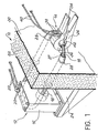
- FIG. 1 there is shown in exploded view a wall 10, such as one of the walls of a cell intended to receive dangerous products, for example explosive products.
- Various devices (not shown), intended for the manipulation of these products, for the detection of certain phenomena and for carrying out measurements of all kinds are also placed inside the cell. These devices can be for example jacks, carriages, doors, relays, as well as measuring and controlling devices of all kinds. They are usually controlled by electrical energy from outside the cell, and for measurement and control devices must transmit certain information to reading or recording systems located outside the cell. cell. Some of these devices must also receive control signals sent outside the cell.
- the transmission of different signals that are electrical operating power of the devices and the information provided in particular by the measurement and control apparatus through the wall 10 takes place by means of a device comprising a supply transformer 12 disposed outside the cell and a distribution transformer 14 disposed inside the cell.
- the transformers 12 and 14 can be either current transformers or voltage transformers depending on the operating point chosen on the characteristic in charge of the device.
- the primary winding and the core of the transformer 12 are arranged in a housing 16 and the secondary winding 18 of this transformer consists of a single turn, preferably made from a bar, a tube or even wires of twisted copper.
- the winding primary of transformer 12 is supplied by a current source (not shown) electrically connected to the outputs 20 of this winding via wires 22.
- the outputs 20 can be connected simultaneously to measurement, playback or recording (not shown).
- the housing 16 enclosing the primary winding and the core of the transformer 12 is carried by a support plate 24 which can be fixed to the wall 10 of the cell.
- the single turn 18 which constitutes the secondary winding of the transformer 12 passes through the wall 10 in a sealed manner so as to constitute the primary winding of the transformer 14.
- the secondary winding thus. that the core of the transformer 14 are arranged inside a removable member such as a clamp 26 intended to be mounted and dismounted remotely by means of a conventional manipulator.
- the clamp 26 is an amperometric clamp whose principle is well known in the art.
- the part of the copper coil 19 disposed inside the cell is received in a sheath 27 fixed in a sealed manner by welds 28 to the internal shielding 30 of the wall 10, the main part 32 of which consists of a layer of lead.
- the sheath 27 thus constitutes a tubular projection of the wall 10 in the cell.
- This structure makes it possible to obtain a perfect seal between the inside and the outside of the cell delimited by the wall 10.
- the sheath 27 constitutes a protuberance from the wall 10, and, more precisely, its internal shielding 30, inside the cell, of such that the turn 18 does not actually penetrate inside the cell although it crosses the wall 10 thereof. This characteristic, essential when the device according to the invention is intended.
- the sheath 27 and the internal shielding 30 of the wall 10 are made of stainless steel, which makes it possible to limit the losses due to the eddy currents.
- the coil 18 may optionally be covered with insulation.
- the copper coil 18 is tightly fixed to the wall 10 at the crossing points by welds 29 made directly between the coil 18 and the internal shielding 30, of the wall 10.
- This shield 30 constitutes a shunt for the turn 18.
- the resistivity of the shield is much greater than that of the turn, the shunt derives only a small part of the current.
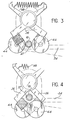
- the clamp 26 includes a handle 34 whose shape is designed so that it can be grasped remotely by a manipulator and two jaws 36 in which are housed the secondary winding and the core of the transformer 14.
- the clamp 26 also comprises two sortias 38 by which the secondary winding of the transformer is electrically connected by means of wires 40 to at least one of the instruments arranged at the inside the cell.
- the turn 18 can be received with a relatively large clearance in the space 42, which facilitates the remote mounting of the clamp 26.
- rollers 44 are rotatably mounted on horns 46 integral with the jaws 36 of the clamp, the latter being biased in the closed position by a spring 48.
- a member 50 fixed to another wall 52 of the cell, defines two facing cam surfaces 54, symmetrical along a plane passing through the axis of the coil 18, on which the rollers roll 44 when the clamp moves perpendicular to the plane defined by the turn and contained in the plane of symmetry of the cam surfaces.
- the cam surfaces 54 are designed and arranged so that the clamp 26 opens when it passes at the level of the coil 18, then closes around it.
- the handle 34 of the clamp 26 comprises a dovetail 56 capable of being received in a corresponding groove formed at the end of a manipulator arm 58 shown in phantom.
- the handle 34 further comprises a guide piston 60 extending the arm 58, and designed to be: received in a cylinder 62 formed in the psroi 52, so as to guide the arm 58 in its displacement along a vertical axis in the variant shown , so that the rollers 44 remain vis-à-vis the cam surfaces 54.
- the rollers 44 are mounted directly on the jaws 36, so as to come into contact with the external surface of the sheath 27 before the end of the jaws.
- a spring 48 also urges the clamp in the closed position.
- the assembly and disassembly of the clamp is carried out as in the variant shown in Figure 2 by moving the clamp along an axis perpendicular to the plane of the coil 18 and passing through the axis thereof.
- the clamp is shown during assembly or disassembly in Figure 3, while the rollers 44 are in contact with the outer surface of the sheath, and in the operating position in Figure 4, the ends of the jaws 36 being in contact with each other.
- rollers are offset relative to each other so as to allow them to overlap.
- clamps 26 can be mounted on the same turn 18, for example by means of the cam surfaces formed on at least one second member 50 'identical to the member 50.
- the shape and orientation of the turn 18 can be adapted according to the envisaged application, so as to allow the movement of the clamps 26 relative to the turn 18.
- the coil 18 can be arranged in a horizontal plane and present inside the cell the shape of an arc of a circle, as illustrated in FIG. 1.
- Such an arrangement can allow, for example, feeding electric motor controlling the rotation of an arm or the operation of a door, the latter directly carrying the clamp (s) 26.
- the coil 18, still arranged in a horizontal plane, can also have inside the cell a straight part along which the clamp 26 can move, the latter being associated, for example, with a carriage capable of move on rails inside the enclosure.
- the carriage can carry a certain number of pliers of the type of pliers 26, the turn 18 then being held regularly by supports and mechanisms automatically controlling the opening of the pliers when they pass vis-à-vis these supports.
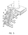
- the turn is rectangular and arranged in a substantially vertical plane, which allows for example the clamp 26 to be associated with a quillotine door, the electric motor controlling the implementation of which is supplied by means of a device according to the invention.
- the device according to the invention is used to transmit a three-phase electric current, intended for the supply of a three-phase device.
- the transformers 12 and 14 are three-phase transformers, which implies that the device comprises three turns 18, 18 'and 18 ", preferably of the same shape, parallel and arranged at equal distance from each other.
- these turns pass through the wall 10 in the same way as the single turn in the embodiment described above.
- These turns receive one or more clamps 26, 26 ′, 26 "whose jaws define three spaces intended to each receive one of the turns.
- the turn 18 and the clamp 26 which have just been fixed on this part therefore play the same role as a socket in known devices.
- no current When the coil 18 is touched, no electrical contact is established, so that any risk of accident is avoided.
- opening and closing of the clamp 26 does not give rise to the elimination and establishment of an electrical contact, so that no electric arc can be created.
- the closing of the clamp is only accompanied by the closing of a magnetic flux in the core disposed inside the clamp.
- the device according to the invention allows remote handling much easier than conventional power outlets. Finally, it allows easy replacement of all wearing parts.
- the wires 22 are connected to a current source (not shown) supplying the primary winding of the transformer 12. Under the effect of the supply current, and via the transformers 12 and 14, an electric current s' established in the circuit comprising the device or devices (s) connected to the wires 40 and the secondary winding of the transformer 14.
- the various devices placed behind the wall 10 are thus energized.
- the yield of such a device can reach approximately 0.5 when the length of the coil 18 is not too great and when the clearance between this turn and the cores of transformers 12 and 14 remains limited.
- a power of around 1KW can then be transmitted to a device located inside the cell delimited by the partition 10.
- the device according to the invention provides double galvanic isolation between the current source connected to terminals 20 and the device to be supplied connected to terminals 38.
- the device according to the invention makes it possible to supply one or more apparatuses placed inside the enclosure, it also makes it possible to transmit through the wall 10, in one or the other direction, coded orders and information.
- the transmission of orders and information takes place by modulated current, in the form of discrete frequencies or frequency variations superimposed on the supply current.
- This coded information can be, for example, measurement results, or else control commands or signaling information.
- the transmitted frequency can reach approximately 10 kHz, and the bandwidth of the device according to the invention is very wide.
- the separation of the coded information and the supply current can then be carried out in a known manner using synchronous filters or detectors before the coded information is transmitted to direct reading devices or to recorders.
- the coil 18 when it is welded to the wall as illustrated in FIG. 2, and the sheath 27 when the coil is received in a sheath welded to the wall, as illustrated Figure 1, are not removable. So all the other parts of the device, and in particular the parts arranged inside the cell, can be changed without requiring any particular disassembly when they are worn or damaged, for example when a particularly corrosive atmosphere prevails inside the enclosure .
- the device according to the invention is therefore particularly safe and reliable and is also distinguished for this reason from the known devices making it possible to transmit electrical signals.
- the device according to the invention can be used in all cases where an electrical outlet is necessary, in order to avoid any risk of accident or explosion.
- the shape and orientation of the turn can be modified depending on the intended application.
- the clamp 26 can be replaced by another removable member and its shape, and in particular that of the handle 34 and the jaws 36, can be modified, in particular when this clamp must be manipulated from a distance.
- the device according to the invention can be used as soon as electrical signals must be transmitted and whatever the nature of the products handled near the device and the nature of the ambient environment.
- the latter can be both a gas and a liquid
- the device according to the invention can be used in an underwater or aquatic environment.
Landscapes
- Engineering & Computer Science (AREA)
- Power Engineering (AREA)
- Architecture (AREA)
- Civil Engineering (AREA)
- Structural Engineering (AREA)
- Physics & Mathematics (AREA)
- General Physics & Mathematics (AREA)
- Transformers For Measuring Instruments (AREA)
- Near-Field Transmission Systems (AREA)
- Patch Boards (AREA)
Applications Claiming Priority (2)
| Application Number | Priority Date | Filing Date | Title |
|---|---|---|---|
| FR7911469A FR2456377A1 (fr) | 1979-05-07 | 1979-05-07 | Procede et dispositif de transmission electrique par un systeme de connexion amovible sans contact |
| FR7911469 | 1979-05-07 |
Publications (2)
| Publication Number | Publication Date |
|---|---|
| EP0018921A1 true EP0018921A1 (de) | 1980-11-12 |
| EP0018921B1 EP0018921B1 (de) | 1984-02-29 |
Family
ID=9225132
Family Applications (1)
| Application Number | Title | Priority Date | Filing Date |
|---|---|---|---|
| EP80400614A Expired EP0018921B1 (de) | 1979-05-07 | 1980-05-06 | Vorrichtung zur elektrischen Übertragung durch ein System lösbarer und kontaktloser Verbindungen |
Country Status (5)
| Country | Link |
|---|---|
| US (1) | US4386280A (de) |
| EP (1) | EP0018921B1 (de) |
| JP (1) | JPS55151312A (de) |
| DE (1) | DE3066738D1 (de) |
| FR (1) | FR2456377A1 (de) |
Cited By (4)
| Publication number | Priority date | Publication date | Assignee | Title |
|---|---|---|---|---|
| EP0058077A3 (de) * | 1981-02-09 | 1982-09-01 | John Murray Fredrickson | Einpflanzbare künstliche Schallquelle |
| GB2171205A (en) * | 1985-02-15 | 1986-08-20 | Delta Technical Services Ltd | Data logging arrangements |
| FR2596195A1 (fr) * | 1986-03-24 | 1987-09-25 | Commissariat Energie Atomique | Procede et dispositif de transmission de courants electriques triphases par un systeme de connexion amovible sans contact |
| EP2592426A1 (de) * | 2011-11-10 | 2013-05-15 | Schneider Electric Industries SAS | Messfühler zur Strommessung in einem elektrischen Kabel |
Families Citing this family (29)
| Publication number | Priority date | Publication date | Assignee | Title |
|---|---|---|---|---|
| US5301096A (en) * | 1991-09-27 | 1994-04-05 | Electric Power Research Institute | Submersible contactless power delivery system |
| US5341280A (en) * | 1991-09-27 | 1994-08-23 | Electric Power Research Institute | Contactless coaxial winding transformer power transfer system |
| US5341083A (en) * | 1991-09-27 | 1994-08-23 | Electric Power Research Institute, Inc. | Contactless battery charging system |
| CA2484957A1 (en) * | 2004-07-07 | 2006-01-07 | Veris Industries, Llc | Split core sensing transformer |
| US7652871B2 (en) * | 2006-01-04 | 2010-01-26 | General Electric Company | Methods and systems for electrical power sub-metering |
| CA2609611A1 (en) * | 2007-09-10 | 2009-03-10 | Veris Industries, Llc | Split core status indicator |
| CA2609629A1 (en) * | 2007-09-10 | 2009-03-10 | Veris Industries, Llc | Current switch with automatic calibration |
| CA2609619A1 (en) | 2007-09-10 | 2009-03-10 | Veris Industries, Llc | Status indicator |
| US8212548B2 (en) | 2008-06-02 | 2012-07-03 | Veris Industries, Llc | Branch meter with configurable sensor strip arrangement |
| US8421443B2 (en) | 2008-11-21 | 2013-04-16 | Veris Industries, Llc | Branch current monitor with calibration |
| US8421639B2 (en) | 2008-11-21 | 2013-04-16 | Veris Industries, Llc | Branch current monitor with an alarm |
| US9335352B2 (en) * | 2009-03-13 | 2016-05-10 | Veris Industries, Llc | Branch circuit monitor power measurement |
| US8749226B2 (en) * | 2010-05-17 | 2014-06-10 | Abb Technology Ag | Line-powered instrument transformer |
| US9146264B2 (en) | 2011-02-25 | 2015-09-29 | Veris Industries, Llc | Current meter with on board memory |
| US10006948B2 (en) | 2011-02-25 | 2018-06-26 | Veris Industries, Llc | Current meter with voltage awareness |
| CA2832898A1 (en) * | 2011-04-14 | 2012-10-18 | Abb Schweiz Ag | Electrostatic shield for a transformer |
| US9329996B2 (en) | 2011-04-27 | 2016-05-03 | Veris Industries, Llc | Branch circuit monitor with paging register |
| US9250308B2 (en) | 2011-06-03 | 2016-02-02 | Veris Industries, Llc | Simplified energy meter configuration |
| US9410552B2 (en) | 2011-10-05 | 2016-08-09 | Veris Industries, Llc | Current switch with automatic calibration |
| US9424975B2 (en) | 2013-08-23 | 2016-08-23 | Veris Industries, Llc | Split core transformer with self-aligning cores |
| US9607749B2 (en) | 2014-01-23 | 2017-03-28 | Veris Industries, Llc | Split core current transformer |
| US9588148B2 (en) | 2014-01-23 | 2017-03-07 | Veris Industries, Llc | Input circuit for current transformer |
| US10371721B2 (en) | 2015-12-28 | 2019-08-06 | Veris Industries, Llc | Configuration system for a power meter |
| US10274572B2 (en) | 2015-12-28 | 2019-04-30 | Veris Industries, Llc | Calibration system for a power meter |
| US10408911B2 (en) | 2015-12-28 | 2019-09-10 | Veris Industries, Llc | Network configurable system for a power meter |
| US10371730B2 (en) | 2015-12-28 | 2019-08-06 | Veris Industries, Llc | Branch current monitor with client level access |
| US11215650B2 (en) | 2017-02-28 | 2022-01-04 | Veris Industries, Llc | Phase aligned branch energy meter |
| US11193958B2 (en) | 2017-03-03 | 2021-12-07 | Veris Industries, Llc | Non-contact voltage sensor |
| US10705126B2 (en) | 2017-05-19 | 2020-07-07 | Veris Industries, Llc | Energy metering with temperature monitoring |
Citations (12)
| Publication number | Priority date | Publication date | Assignee | Title |
|---|---|---|---|---|
| FR671744A (fr) * | 1929-03-20 | 1929-12-18 | Cfcmug | Transformateur de courant |
| GB497075A (en) * | 1937-06-03 | 1938-12-05 | Joseph Fodor | Electrical supply or distribution systems particularly for use in coal mines or other explosive atmospheres |
| US2413195A (en) * | 1942-12-21 | 1946-12-24 | Pacific Electric Mfg Corp | High potential current transformer means |
| FR952243A (fr) * | 1946-08-22 | 1949-11-14 | Westinghouse Electric Corp | Fermeture hermétique pour appareils électriques |
| FR1303365A (fr) * | 1961-10-11 | 1962-09-07 | Siemens Ag | Transformateur d'intensité à haute tension avec plusieurs enroulements secondaires traversés par le flux produit par le courant primaire |
| GB1099866A (en) * | 1965-09-09 | 1968-01-17 | Geodyne Corp | Inductive coupling apparatus |
| GB1199256A (en) * | 1966-10-06 | 1970-07-22 | Donovan Electrical Company Ltd | Safety Device Primarily for Machine Guards |
| US3667342A (en) * | 1970-04-08 | 1972-06-06 | Us Navy | Magnetic weapon link transducer |
| US3742408A (en) * | 1969-12-12 | 1973-06-26 | Bissett Berman Corp | Inductively coupled connector |
| US3793166A (en) * | 1970-01-07 | 1974-02-19 | American Smelting Refining | Electrical current measurement and rapidly locating and positively identifying cathodes having abnormal electrical conditions associated therewith in an electrolytic copper refining process tankhouse |
| DE2429049A1 (de) * | 1974-06-18 | 1976-01-08 | Hauff Technik Kg | Dichte wanddurchfuehrung in einem rahmen |
| DE2543828A1 (de) * | 1975-10-01 | 1977-04-14 | Hoechst Ag | Vorrichtung zum messen von elektrischem strom |
Family Cites Families (2)
| Publication number | Priority date | Publication date | Assignee | Title |
|---|---|---|---|---|
| US2476121A (en) * | 1946-09-11 | 1949-07-12 | Daven Company | Current transformer |
| JPS5550606Y2 (de) * | 1976-10-18 | 1980-11-26 |
-
1979
- 1979-05-07 FR FR7911469A patent/FR2456377A1/fr active Granted
-
1980
- 1980-05-01 US US06/145,753 patent/US4386280A/en not_active Expired - Lifetime
- 1980-05-06 JP JP5877580A patent/JPS55151312A/ja active Granted
- 1980-05-06 DE DE8080400614T patent/DE3066738D1/de not_active Expired
- 1980-05-06 EP EP80400614A patent/EP0018921B1/de not_active Expired
Patent Citations (12)
| Publication number | Priority date | Publication date | Assignee | Title |
|---|---|---|---|---|
| FR671744A (fr) * | 1929-03-20 | 1929-12-18 | Cfcmug | Transformateur de courant |
| GB497075A (en) * | 1937-06-03 | 1938-12-05 | Joseph Fodor | Electrical supply or distribution systems particularly for use in coal mines or other explosive atmospheres |
| US2413195A (en) * | 1942-12-21 | 1946-12-24 | Pacific Electric Mfg Corp | High potential current transformer means |
| FR952243A (fr) * | 1946-08-22 | 1949-11-14 | Westinghouse Electric Corp | Fermeture hermétique pour appareils électriques |
| FR1303365A (fr) * | 1961-10-11 | 1962-09-07 | Siemens Ag | Transformateur d'intensité à haute tension avec plusieurs enroulements secondaires traversés par le flux produit par le courant primaire |
| GB1099866A (en) * | 1965-09-09 | 1968-01-17 | Geodyne Corp | Inductive coupling apparatus |
| GB1199256A (en) * | 1966-10-06 | 1970-07-22 | Donovan Electrical Company Ltd | Safety Device Primarily for Machine Guards |
| US3742408A (en) * | 1969-12-12 | 1973-06-26 | Bissett Berman Corp | Inductively coupled connector |
| US3793166A (en) * | 1970-01-07 | 1974-02-19 | American Smelting Refining | Electrical current measurement and rapidly locating and positively identifying cathodes having abnormal electrical conditions associated therewith in an electrolytic copper refining process tankhouse |
| US3667342A (en) * | 1970-04-08 | 1972-06-06 | Us Navy | Magnetic weapon link transducer |
| DE2429049A1 (de) * | 1974-06-18 | 1976-01-08 | Hauff Technik Kg | Dichte wanddurchfuehrung in einem rahmen |
| DE2543828A1 (de) * | 1975-10-01 | 1977-04-14 | Hoechst Ag | Vorrichtung zum messen von elektrischem strom |
Cited By (7)
| Publication number | Priority date | Publication date | Assignee | Title |
|---|---|---|---|---|
| EP0058077A3 (de) * | 1981-02-09 | 1982-09-01 | John Murray Fredrickson | Einpflanzbare künstliche Schallquelle |
| GB2171205A (en) * | 1985-02-15 | 1986-08-20 | Delta Technical Services Ltd | Data logging arrangements |
| GB2171205B (en) * | 1985-02-15 | 1989-07-26 | Delta Technical Services Ltd | Data logging arrangements and methods of obtaining data |
| FR2596195A1 (fr) * | 1986-03-24 | 1987-09-25 | Commissariat Energie Atomique | Procede et dispositif de transmission de courants electriques triphases par un systeme de connexion amovible sans contact |
| EP2592426A1 (de) * | 2011-11-10 | 2013-05-15 | Schneider Electric Industries SAS | Messfühler zur Strommessung in einem elektrischen Kabel |
| FR2982673A1 (fr) * | 2011-11-10 | 2013-05-17 | Schneider Electric Ind Sas | Capteur pour la mesure d'un courant dans un cable electrique |
| CN103197116A (zh) * | 2011-11-10 | 2013-07-10 | 施耐德电器工业公司 | 一种用于测量电缆中电流的传感器 |
Also Published As
| Publication number | Publication date |
|---|---|
| FR2456377B1 (de) | 1984-10-12 |
| EP0018921B1 (de) | 1984-02-29 |
| DE3066738D1 (en) | 1984-04-05 |
| JPS6349361B2 (de) | 1988-10-04 |
| JPS55151312A (en) | 1980-11-25 |
| US4386280A (en) | 1983-05-31 |
| FR2456377A1 (fr) | 1980-12-05 |
Similar Documents
| Publication | Publication Date | Title |
|---|---|---|
| EP0018921B1 (de) | Vorrichtung zur elektrischen Übertragung durch ein System lösbarer und kontaktloser Verbindungen | |
| CA2138634C (fr) | Ligne a haute tension a isolation gazeuse pour longue distance | |
| EP0660479B1 (de) | Gasisoliertes einphasiges Stromkabel | |
| EP2887076B1 (de) | Stromsensor mit Rogowskispule, und Herstellungsverfahren eines solchen Stromsensors | |
| EP0543681A1 (de) | Mittelspannungslastschalter für innen oder aussen | |
| EP0216694B1 (de) | Vorrichtung zur Echtzeitkontrolle von Schweissungen, insbesondere für nicht direkt beobachtbare Schweissstellen | |
| FR2929454A1 (fr) | Dispositif de connexion de deux cables supraconducteurs | |
| FR2517068A1 (fr) | Methode et dispositif pour mettre dans une position relative determinee deux elements immerges dans un milieu liquide conducteur | |
| EP2605351B1 (de) | Winkelstück mit mehreren Ausrichtungswinkeln für Hochspannungsleitungen | |
| FR2773396A1 (fr) | Outil de test pour determiner la pression des doigts de contact dans un disjoncteur | |
| CA2144671A1 (fr) | Dispositif de controle et de commande pour ligne de transport electrique blindee | |
| FR2717582A1 (fr) | Dispositif de mesure d'une chute de tension sur un conducteur sous tension. | |
| FR2625378A1 (fr) | Dispositif electrotechnique a protection antideflagrante | |
| EP1610352B1 (de) | Elektrische Trennvorrichtung | |
| EP0106767B1 (de) | Vorrichtung zur Messung der Lichtbogenspannung in einem elektrischen Ofen | |
| FR2596195A1 (fr) | Procede et dispositif de transmission de courants electriques triphases par un systeme de connexion amovible sans contact | |
| EP0112757B1 (de) | Elektromagnetische Strommessvorrichtung mit schwenkbaren Armen | |
| EP0926695B1 (de) | Differentialmoduls und elektrische Anschlussvorrichtung des Differentialmoduls an einem Schutzschalter | |
| EP0959362B1 (de) | Vorrichtung zur Messung einer mit der Rotation eines Organs zusammenhängenden physikalischen Grösse | |
| EP2990811B1 (de) | Kontaktlose messvorrichtung für elektrische spannung in einem mittel- oder hochspannungs-stromnetzkabel | |
| CA1158721A (fr) | Dispositif et procede de detection des defauts au moyen de courants de foucault | |
| EP0452220A1 (de) | Zwischenverbindungseinrichtung für die Kupplung von zwei elektrischen Kabeln ohne Abisolierung | |
| CA1177536A (fr) | Detection et localisation de defauts electriques et decharges partielles | |
| FR3050176B1 (fr) | Nacelle pour ensemble propulsif | |
| EP0174227B1 (de) | Kontaktloser Verschiebungssensor |
Legal Events
| Date | Code | Title | Description |
|---|---|---|---|
| PUAI | Public reference made under article 153(3) epc to a published international application that has entered the european phase |
Free format text: ORIGINAL CODE: 0009012 |
|
| AK | Designated contracting states |
Designated state(s): BE CH DE GB IT |
|
| 17P | Request for examination filed |
Effective date: 19810415 |
|
| ITF | It: translation for a ep patent filed | ||
| GRAA | (expected) grant |
Free format text: ORIGINAL CODE: 0009210 |
|
| AK | Designated contracting states |
Designated state(s): BE CH DE GB IT LI |
|
| REF | Corresponds to: |
Ref document number: 3066738 Country of ref document: DE Date of ref document: 19840405 |
|
| PLBE | No opposition filed within time limit |
Free format text: ORIGINAL CODE: 0009261 |
|
| STAA | Information on the status of an ep patent application or granted ep patent |
Free format text: STATUS: NO OPPOSITION FILED WITHIN TIME LIMIT |
|
| 26N | No opposition filed | ||
| PGFP | Annual fee paid to national office [announced via postgrant information from national office to epo] |
Ref country code: BE Payment date: 19890502 Year of fee payment: 10 |
|
| PGFP | Annual fee paid to national office [announced via postgrant information from national office to epo] |
Ref country code: CH Payment date: 19890503 Year of fee payment: 10 |
|
| ITTA | It: last paid annual fee | ||
| PG25 | Lapsed in a contracting state [announced via postgrant information from national office to epo] |
Ref country code: LI Effective date: 19900531 Ref country code: CH Effective date: 19900531 Ref country code: BE Effective date: 19900531 |
|
| BERE | Be: lapsed |
Owner name: COMMISSARIAT A L'ENERGIE ATOMIQUE ETABLISSEMENT D Effective date: 19900531 |
|
| REG | Reference to a national code |
Ref country code: CH Ref legal event code: PL |
|
| PGFP | Annual fee paid to national office [announced via postgrant information from national office to epo] |
Ref country code: DE Payment date: 19920429 Year of fee payment: 13 |
|
| PG25 | Lapsed in a contracting state [announced via postgrant information from national office to epo] |
Ref country code: DE Effective date: 19940201 |
|
| PGFP | Annual fee paid to national office [announced via postgrant information from national office to epo] |
Ref country code: GB Payment date: 19950427 Year of fee payment: 16 |
|
| PG25 | Lapsed in a contracting state [announced via postgrant information from national office to epo] |
Ref country code: GB Effective date: 19960506 |
|
| GBPC | Gb: european patent ceased through non-payment of renewal fee |
Effective date: 19960506 |