EP0018954A1 - Apparat zum Reduzieren der Wassermenge in einem feuchten und wässerigen Bandmaterial - Google Patents
Apparat zum Reduzieren der Wassermenge in einem feuchten und wässerigen Bandmaterial Download PDFInfo
- Publication number
- EP0018954A1 EP0018954A1 EP80850049A EP80850049A EP0018954A1 EP 0018954 A1 EP0018954 A1 EP 0018954A1 EP 80850049 A EP80850049 A EP 80850049A EP 80850049 A EP80850049 A EP 80850049A EP 0018954 A1 EP0018954 A1 EP 0018954A1
- Authority
- EP
- European Patent Office
- Prior art keywords
- roller
- press
- rollers
- satelite
- nip
- Prior art date
- Legal status (The legal status is an assumption and is not a legal conclusion. Google has not performed a legal analysis and makes no representation as to the accuracy of the status listed.)
- Granted
Links
Images


Classifications
-
- D—TEXTILES; PAPER
- D21—PAPER-MAKING; PRODUCTION OF CELLULOSE
- D21F—PAPER-MAKING MACHINES; METHODS OF PRODUCING PAPER THEREON
- D21F3/00—Press section of machines for making continuous webs of paper
- D21F3/02—Wet presses
- D21F3/04—Arrangements thereof
- D21F3/045—Arrangements thereof including at least one extended press nip
-
- D—TEXTILES; PAPER
- D21—PAPER-MAKING; PRODUCTION OF CELLULOSE
- D21G—CALENDERS; ACCESSORIES FOR PAPER-MAKING MACHINES
- D21G1/00—Calenders; Smoothing apparatus
Definitions
- An apparatus for reducing the amount of water in a moist and watery material web is provided.
- the present invention relates to an apparatus for reducing the amount of water in a moist and watery material web, by means of one or more press nips, each being provided between a press roller and a roller-formed body, which at least to a certain part being deformable for controlling of the length of said press nip.
- a paper or cellulose machine dewatering or demoisturizing of a moist and watery fibre web, which in such an event consists of a paper web, is carried out in the press section of the machine, after transfer of the web from the forming section of the machine.
- the paper web In the transfer from the forming section to the press section, the paper web has a relatively low dry solids content. It is desirable to remove as much water as possible from the paper web in the press section, since subsequent dewatering by drying in a subsequent drying section in the machine is conserably more expensive.
- a plurality of press nips are normally provided which are formed of two cooperating rollers. It is also possible that the one of the rollers is provided with a suction zone for facilitating the removal of water from the fibre web.
- the moist fibre web is transported and moved through the press nip by means of one or more press felts and possibly also a pressfabric.
- the press nip formed between the two press rollers has, because of the contact between the rollers, theoretically the form of a line in the axial direction of the rollers and, because of a certain compression as a result of the compression pressure, the line has a certain width.
- the press nip may be considered as having a certain length in a direction at right angles to the axial direction of the rollers and a narrow press zone is thereby formed.
- the compression pressure in the zone runs from zero rapidly up to a maximum level and thereafter rapidly falls off to zero.
- hydraulic counter-pressure can be built up in the felt because this is not capable of storing and conveying off the amount of water which, during a very short time, is pressed out from the fibre web.
- this hydraulic counter-pressure reaches a certain level, so-called crushing occurs in the paper web, and, consequently, the compression pressure and/or the machine speed must be reduced with a consequential reduction of production.
- the production capacity of a paper machine is, thus, dependent upon the size of the hydraulic counter-pressure in the felt which, in its turn, is dependent upon the compression pressure and the machine speed.
- the fabric press with an incompressible fabric is one method; another method is the application of a combination felt in which the base portion proper is incompressible and is open in order to allow for storage and removal of the pressed-out water.
- a further method is to extend the press nip or press nip period, that is to say that period during which the fibre web is subjected to compression pressure. According to this method, it is attempted to exercise compression pressure for a longer period of time than in normal press nips.
- This methodology has also been developed for making possible the application of one-step pressing, that is to say a reduction of the number of press units to a sole unit as a result of the extended pressing period:
- the extended press nip is realised in that one or more press belts cooperate with a press roller.
- the moist and watery paper web is introduced between the press belt .and the press roller together with a press fabric and possibly also a press fabric.
- the compression pressure between the press belt and the press roller must amount to approximately 2-3MPa for attaining the desired dewatering effect.
- the specific tensile force in the press belt will be very high and great difficulties have been experienced in being able to manufacture a press belt which permits of such high compression pressure.
- the diameter of the press roller is 1,5 m
- the press belt must, for attaining the above- mentioned compression pressure, be able to tolerate a tensile force of 1,5-2,3 MN/m. This has entailed that such apparatuses for realising extended press nip have not come into practical utilisation.
- the great tensile force in the press belt also entails a risk for bending the pivot rollers of the press belt, which in its turn entails an uneven distribution of the compression pressure in the press nip.
- U S Patent Specification No 3 808 096 describes an arrangement with an extended press nip which consists of a press roller and an endless belt.
- the endless belt forms an enclosed compartment for accommodating a liquid under excess pressure.
- the pivot rollers are disposed within the belt for-retaining it in operative position. The position on the rollers determines the length of the press nip and this cannot be changed without a replacement of the press belt. This entails a great inconvenience in being able to regulate the length of the press nip. Since the press nip is of great length, there is a risk for permanent compression of the paper web, whereby this obtains a resultant poor bulk. When the press nip is of slight length, the specific compression pressure must be raised for obtaining the same dewatering capacity, Which entails a risk for crushing both the paper web and the press felt.
- U S Patent Specification No 3 293 121 describes an arrangement with a deformable roller-like body positioned between two rollers.
- the deformable roller-like body provides together with one of the rollers an extended press nip controlling in length and pressure.
- the roller-like body has to be journalled in the frame of the machine in order to be positioned and the moments provided during the operation of the roller-like body has to be transfered from the envelope surface of the body to the shaft of the body. Because of the deformable nature of the roller-like body the only possible connection between the envelope surface and the shaft is via the gables. These gables has to be flexible in order that their form has to follow the form of the roller-like body. This is one of the main problems with the arrangement described in the above mentioned patent.
- the above- outlined tenchical problem frame work is solved in that the apparatus discosed by way of introduction is characterized in that said roller-formed body being a central roller in cooperation with at least three satelite rollers. positioned around the central roller for positioning said roller in a balanced condition, i.n that said press nip being provided between at least one of said satelite rollers and said roller-formed central roller and in that the pressure between said satelite roller and said roller-formed central roller being controllable almost independently of the length of the press nip, provided by the deformation, by a change of the pressure inside sajd roller-formed body.
- the roller-like body needs no pivot rollers which, as a result of bending, may give rise to uneven compression pressure.
- the roller-like body is constructed such that an increase in pressure at normal excess pressure merely entails a very slight change of the size of the press nip.
- the length of the press nip is adjustable by a regulation of the distance between the fixed press rollers.
- roller-like body need not be fixedly disposed between the press rollers, by which is meant fixedly journalled.
- Merely side blocks need be disposed at the ends of the roller-like body in order to prevent it from "wandering" in an axial direction.
- the press nip may optionally be divided up into several small press zones or one single long press zone.
- the different press zones may be individually felted, that is to say different felts run through the different zones, whereby the dewatering capacity is increased.
- the arrangement according to the present invention permits also substantially vibration-free operation and places low requirements on space.
- roller-like body is deformable, the risk of burning the felt because of the collection of wadding ahead of the press nip will be reduced, since the passage of wadding is allowed because of the deformation capacity of the roller-like body.
- the press nip may also be considered as flexible to a certain degree, whereby the felt is not broken up by pulp waste which, in conventional apparatuses, often penetrate into the felt.
- the roller-like body according to the invention may be divided into different compartments and these may contain different media.
- the division of the interior of the roller-like body into different compartments results in spaces of small volume, whereby the risks in possible leakage are to a great extent obviated.
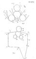
- Fig 1 schematically shows a side elevation of an embodiment of an apparatus according to the present invention.
- Fig 2 schematically shows a side elevation of a further embodiment of an apparatus according to the present invention.
- Fig 3 shows, on a larger scale, a schematic part side elevation of the embodiment of the present invention shown in fig 1.
- Fig 4 shows, on a larger scale, a schematic side elevation of yet another embodiment of the apparatus according to the present invention.
- Fig 5 shows, on a larger scale, a schematic side elevation of still a further embodiment of the apparatus according to the present invention.
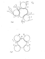
- Fig 6 shows, on a larger scale, a schematic side elevation of a further embodiment of the apparatus according to the present invention.
- Fig 7 shows, on a larger scale, a schematic side elevation of a further embodiment of the apparatus according to the present invention.
- the embodiment of the apparatus according to the present invention shown in fig 1 forms a press section in a paper machine, parts of the forming section and a drying section of the paper machine being also. shown.
- a fibre web 1 is formed on a forming fabric 2, which comes from the forming section.
- the continuous fibre web is removed from the fabric 2 bv means of a pick-up roller 3.
- the fibre web 1 runs around the roller 3 into a first press nip 4 between the press roller 3 and a roller-like body 5.
- further press rollers 8 and 9 furtherpress nips 6 and 7 are arranged against the roller-like body 5.
- the fibre web 1 passes the press nips 4, 6 and 7 and leaves the press section by the intermediary of a removal roller 10 and is fed from the press section to a drying section, of which but a part is shown.
- a press fabric 11 and a press tilt 12 pass through the first press nip 4, these running over return rollers 13 and 14, respectevely.
- two suction boxes 15 are provided for dewatering the felt.
- the press fabric 11 is incompressible and, thereby, the first press nip 4 may be considered as forming a so-called fabric press.
- the fibre web 1 passes through the two otherpress nips 6 and 7 together with press felts 16 and 17, respectively which are disposed on return rollers 14 and at which are provided suction boxes 15.
- fig 2 an embodiment of the present invention which is arranged in a conventional press section.
- the lower press roller has, according to the present invention, been replaced by a roller-like body 18 which is supported by two support rollers 19 and an upper press roller 20.
- the fibre web 1 passes through the thus formed press nip 22 together with a press felt 21 which runs over return rollers 14.
- fig 3 is shown the embodiment according to the present invention shown in a press section in fig 1, on a larger scale.
- fig 4 is shown a simialar embodiment to that of fig 3 but with a further small press roller 23 for forming a further small press nip 24 against the roller-like body 5.
- the press nip 24 forms a so-called prepress nip.
- the pressure rollers 3, 8, 9 may have different diameters and be positioned with different angular spacing.
- the pressure inside the roller-like body 5, the angular spacing of the pressure rollers and the distance between the pressure rollers are adjustable during operation in order to control the specific compression pressure and the length of the press nip independently of each other.
- the different press nips can but do not have to be individually felted.
- One and the same felt may pass through several press nips.
- several felts may be disposed in one or more of the press nips, the paper web passing through the press nip located between, for example, two felts.
- fig 5 is shown a part of an embodiment of an apparatus according to the present invention, according to wich a fibre web 1 runs through a press nip 25 between two press felts 26 and 27.
- the press nip 25 is formed between a roller-like body 5 and three press rollers 3, 8 and 9.
- fig 6 an arrangement of an apparatus according to the present invention, which arrangement is of principally the same type as the arrangement shown in fig 3 with the only exeption that the angular spacing between the rollers is different.
- the angular spacing between the rollers 3 and 8 is less,'while the angular spacing between the rollers 3 and 9 is larger and largest between the rollers 8 and 9.
- the invention is not limited to the arrangement of three press rollers or satelite rollers.
- fig 7 is shown an embodiment of the present invention with a central roller-formed body 28 and for satelite rollers 29, 30, 31, 32.
- An apparatus according to the present invention may also be used for other types of treatment of a fibre web than dewatering.
- the apparatus may be used in calendering, in which it is not necessary to include the felts in the system.
- roller-like body 5 be of a construction which permits expansion to a certain diameter, in which a further pressure increase within the roller-like body 5 should not result in any appreciable increase of the diameter of the roller-like body, but should merely give rise to an increased specific pressure in the different press nips.
- roller-like body 5 may be called a central roller and the pressure rollers 3, 8, 9 may be called satelite rollers in the different embodiments described and shown.
Landscapes
- Paper (AREA)
- Braking Arrangements (AREA)
- Treatment Of Fiber Materials (AREA)
- Electrical Discharge Machining, Electrochemical Machining, And Combined Machining (AREA)
- Water Treatment By Sorption (AREA)
Priority Applications (1)
| Application Number | Priority Date | Filing Date | Title |
|---|---|---|---|
| AT80850049T ATE6680T1 (de) | 1979-05-07 | 1980-04-10 | Apparat zum reduzieren der wassermenge in einem feuchten und waesserigen bandmaterial. |
Applications Claiming Priority (2)
| Application Number | Priority Date | Filing Date | Title |
|---|---|---|---|
| SE7903953 | 1979-05-07 | ||
| SE7903953A SE7903953L (sv) | 1979-05-07 | 1979-05-07 | Anordning for reducering av vattenmengden i en fuktig och vattnig materialbana |
Publications (2)
| Publication Number | Publication Date |
|---|---|
| EP0018954A1 true EP0018954A1 (de) | 1980-11-12 |
| EP0018954B1 EP0018954B1 (de) | 1984-03-14 |
Family
ID=20337979
Family Applications (1)
| Application Number | Title | Priority Date | Filing Date |
|---|---|---|---|
| EP80850049A Expired EP0018954B1 (de) | 1979-05-07 | 1980-04-10 | Apparat zum Reduzieren der Wassermenge in einem feuchten und wässerigen Bandmaterial |
Country Status (11)
| Country | Link |
|---|---|
| EP (1) | EP0018954B1 (de) |
| JP (1) | JPS569496A (de) |
| AT (1) | ATE6680T1 (de) |
| AU (1) | AU532802B2 (de) |
| BR (1) | BR8002492A (de) |
| CA (1) | CA1125559A (de) |
| DE (1) | DE3066914D1 (de) |
| ES (1) | ES491193A0 (de) |
| FI (1) | FI801233A7 (de) |
| MX (1) | MX153039A (de) |
| SE (1) | SE7903953L (de) |
Cited By (2)
| Publication number | Priority date | Publication date | Assignee | Title |
|---|---|---|---|---|
| FR2557895A1 (fr) * | 1984-01-06 | 1985-07-12 | Ahlstroem Oy | Presse pour l'extraction de l'eau de materiaux en bandes, notamment pour machines a papier. |
| WO1998044196A1 (en) * | 1997-04-02 | 1998-10-08 | Valmet Corporation | Calendering method and a calender that makes use of the method |
Families Citing this family (1)
| Publication number | Priority date | Publication date | Assignee | Title |
|---|---|---|---|---|
| DE3808293C2 (de) * | 1988-03-12 | 1994-08-18 | Voith Gmbh J M | Langspalt-Preßwalze |
Citations (4)
| Publication number | Priority date | Publication date | Assignee | Title |
|---|---|---|---|---|
| US1563130A (en) * | 1924-08-22 | 1925-11-24 | Milton T Weston | Pneumatic press roll for paper machines |
| FR1094585A (fr) * | 1952-12-13 | 1955-05-23 | Presse à rouleaux, destinée en particulier à l'expression de fruits | |
| US3293121A (en) * | 1963-10-09 | 1966-12-20 | Black Clawson Co | Pneumatically pressurized paper wet press assembly |
| US3808096A (en) * | 1972-02-16 | 1974-04-30 | Beloit Corp | Figure eight cylinder press for defining an extended press nip |
-
1979
- 1979-05-07 SE SE7903953A patent/SE7903953L/ not_active Application Discontinuation
-
1980
- 1980-04-10 DE DE8080850049T patent/DE3066914D1/de not_active Expired
- 1980-04-10 AT AT80850049T patent/ATE6680T1/de active
- 1980-04-10 EP EP80850049A patent/EP0018954B1/de not_active Expired
- 1980-04-17 FI FI801233A patent/FI801233A7/fi not_active Application Discontinuation
- 1980-04-23 BR BR8002492A patent/BR8002492A/pt unknown
- 1980-04-30 AU AU57904/80A patent/AU532802B2/en not_active Ceased
- 1980-04-30 MX MX182156A patent/MX153039A/es unknown
- 1980-05-06 JP JP5874680A patent/JPS569496A/ja active Pending
- 1980-05-06 ES ES491193A patent/ES491193A0/es active Granted
- 1980-05-07 CA CA351,403A patent/CA1125559A/en not_active Expired
Patent Citations (4)
| Publication number | Priority date | Publication date | Assignee | Title |
|---|---|---|---|---|
| US1563130A (en) * | 1924-08-22 | 1925-11-24 | Milton T Weston | Pneumatic press roll for paper machines |
| FR1094585A (fr) * | 1952-12-13 | 1955-05-23 | Presse à rouleaux, destinée en particulier à l'expression de fruits | |
| US3293121A (en) * | 1963-10-09 | 1966-12-20 | Black Clawson Co | Pneumatically pressurized paper wet press assembly |
| US3808096A (en) * | 1972-02-16 | 1974-04-30 | Beloit Corp | Figure eight cylinder press for defining an extended press nip |
Cited By (3)
| Publication number | Priority date | Publication date | Assignee | Title |
|---|---|---|---|---|
| FR2557895A1 (fr) * | 1984-01-06 | 1985-07-12 | Ahlstroem Oy | Presse pour l'extraction de l'eau de materiaux en bandes, notamment pour machines a papier. |
| WO1998044196A1 (en) * | 1997-04-02 | 1998-10-08 | Valmet Corporation | Calendering method and a calender that makes use of the method |
| US6397739B1 (en) | 1997-04-02 | 2002-06-04 | Valmet Corporation | Calendering method and a calender that makes use of the method |
Also Published As
| Publication number | Publication date |
|---|---|
| FI801233A7 (fi) | 1981-01-01 |
| AU532802B2 (en) | 1983-10-13 |
| ES8101162A1 (es) | 1980-12-01 |
| AU5790480A (en) | 1980-11-13 |
| DE3066914D1 (en) | 1984-04-19 |
| SE7903953L (sv) | 1980-11-08 |
| ATE6680T1 (de) | 1984-03-15 |
| CA1125559A (en) | 1982-06-15 |
| MX153039A (es) | 1986-07-22 |
| ES491193A0 (es) | 1980-12-01 |
| JPS569496A (en) | 1981-01-30 |
| EP0018954B1 (de) | 1984-03-14 |
| BR8002492A (pt) | 1980-12-09 |
Similar Documents
| Publication | Publication Date | Title |
|---|---|---|
| KR870002129B1 (ko) | 제지기에 있어서 웨브이송 장치 | |
| US4075056A (en) | Press section structure | |
| EP0657579B1 (de) | Presspartie einer Papiermaschine mit einer Breitnippresse | |
| US5389205A (en) | Method for dewatering of a paper web by pressing using an extended nip shoe pre-press zone on the forming wire | |
| EP0770727B1 (de) | Verfahren und Vorrichtung zur Entwässerung einer Papierbahn durch Pressen | |
| JP3326182B2 (ja) | エクステンデッドニッププレスを用いている抄紙機のプレスセクション | |
| US4661206A (en) | Wet press for dewatering a material web with plural pressure pockets and unsymmetrical arrangement | |
| AU2001282740B2 (en) | Twin-wire belt press | |
| US4496429A (en) | Extended nip press for a paper machine | |
| AU2001282740A1 (en) | Twin-wire belt press | |
| EP0018954B1 (de) | Apparat zum Reduzieren der Wassermenge in einem feuchten und wässerigen Bandmaterial | |
| CA2294903C (en) | Device for dewatering solid/liquid suspensions, especially pulp suspensions | |
| US6221214B1 (en) | Wet press and method for treating a fibrous material web | |
| ATE220743T1 (de) | Pressenpartie | |
| US9822485B2 (en) | Compact former section | |
| US3331734A (en) | Paper machine press and felt assembly | |
| US3185617A (en) | Divided press | |
| US6616810B1 (en) | Device for removing water from a fibrous material strip | |
| EP1936026A1 (de) | Nassteil für eine Maschine zur Herstellung von Faserstoffbahnen, insbesondere Papiermaschine zur Herstellung holzfreier Papiere | |
| US5749157A (en) | Dryer section for an apparatus for the production of a paper web | |
| SU929773A1 (ru) | Пресс дл обезвоживани полотна из волокнистого материала | |
| CA2294389C (en) | Device for dewatering solid/liquid suspensions, especially pulp suspensions | |
| EP3366836A1 (de) | Pressenpartie einer maschine zur herstellung einer faserstoffbahn | |
| EP0401190A2 (de) | Presspartie an Papier- oder Kartonmaschine | |
| WO2021069127A1 (de) | Tissuemaschine |
Legal Events
| Date | Code | Title | Description |
|---|---|---|---|
| PUAI | Public reference made under article 153(3) epc to a published international application that has entered the european phase |
Free format text: ORIGINAL CODE: 0009012 |
|
| AK | Designated contracting states |
Designated state(s): AT BE CH DE FR GB IT NL SE |
|
| 17P | Request for examination filed |
Effective date: 19810507 |
|
| ITF | It: translation for a ep patent filed | ||
| GRAA | (expected) grant |
Free format text: ORIGINAL CODE: 0009210 |
|
| AK | Designated contracting states |
Designated state(s): AT BE CH DE FR GB IT LI NL SE |
|
| REF | Corresponds to: |
Ref document number: 6680 Country of ref document: AT Date of ref document: 19840315 Kind code of ref document: T |
|
| REF | Corresponds to: |
Ref document number: 3066914 Country of ref document: DE Date of ref document: 19840419 |
|
| ET | Fr: translation filed | ||
| PGFP | Annual fee paid to national office [announced via postgrant information from national office to epo] |
Ref country code: FR Payment date: 19840424 Year of fee payment: 5 |
|
| PGFP | Annual fee paid to national office [announced via postgrant information from national office to epo] |
Ref country code: CH Payment date: 19840427 Year of fee payment: 5 |
|
| PGFP | Annual fee paid to national office [announced via postgrant information from national office to epo] |
Ref country code: DE Payment date: 19840530 Year of fee payment: 5 |
|
| PGFP | Annual fee paid to national office [announced via postgrant information from national office to epo] |
Ref country code: SE Payment date: 19840630 Year of fee payment: 5 Ref country code: BE Payment date: 19840630 Year of fee payment: 5 |
|
| PLBE | No opposition filed within time limit |
Free format text: ORIGINAL CODE: 0009261 |
|
| STAA | Information on the status of an ep patent application or granted ep patent |
Free format text: STATUS: NO OPPOSITION FILED WITHIN TIME LIMIT |
|
| 26N | No opposition filed | ||
| PGFP | Annual fee paid to national office [announced via postgrant information from national office to epo] |
Ref country code: AT Payment date: 19860415 Year of fee payment: 7 |
|
| PGFP | Annual fee paid to national office [announced via postgrant information from national office to epo] |
Ref country code: NL Payment date: 19860430 Year of fee payment: 7 |
|
| PG25 | Lapsed in a contracting state [announced via postgrant information from national office to epo] |
Ref country code: AT Effective date: 19870410 |
|
| PG25 | Lapsed in a contracting state [announced via postgrant information from national office to epo] |
Ref country code: SE Effective date: 19870411 |
|
| PG25 | Lapsed in a contracting state [announced via postgrant information from national office to epo] |
Ref country code: LI Effective date: 19870430 Ref country code: CH Effective date: 19870430 |
|
| BERE | Be: lapsed |
Owner name: NORDISKAFILT A.B. Effective date: 19870430 |
|
| PG25 | Lapsed in a contracting state [announced via postgrant information from national office to epo] |
Ref country code: NL Effective date: 19871101 |
|
| NLV4 | Nl: lapsed or anulled due to non-payment of the annual fee | ||
| PG25 | Lapsed in a contracting state [announced via postgrant information from national office to epo] |
Ref country code: FR Free format text: LAPSE BECAUSE OF NON-PAYMENT OF DUE FEES Effective date: 19871230 |
|
| GBPC | Gb: european patent ceased through non-payment of renewal fee | ||
| REG | Reference to a national code |
Ref country code: CH Ref legal event code: PL |
|
| PG25 | Lapsed in a contracting state [announced via postgrant information from national office to epo] |
Ref country code: DE Effective date: 19880101 |
|
| REG | Reference to a national code |
Ref country code: FR Ref legal event code: ST |
|
| PG25 | Lapsed in a contracting state [announced via postgrant information from national office to epo] |
Ref country code: GB Effective date: 19881118 |
|
| PG25 | Lapsed in a contracting state [announced via postgrant information from national office to epo] |
Ref country code: BE Effective date: 19890430 |
|
| EUG | Se: european patent has lapsed |
Ref document number: 80850049.0 Effective date: 19880906 |