EP0019009A1 - Strangübertragungsvorrichtung - Google Patents
Strangübertragungsvorrichtung Download PDFInfo
- Publication number
- EP0019009A1 EP0019009A1 EP79102322A EP79102322A EP0019009A1 EP 0019009 A1 EP0019009 A1 EP 0019009A1 EP 79102322 A EP79102322 A EP 79102322A EP 79102322 A EP79102322 A EP 79102322A EP 0019009 A1 EP0019009 A1 EP 0019009A1
- Authority
- EP
- European Patent Office
- Prior art keywords
- hank
- integral
- head
- guides
- rods
- Prior art date
- Legal status (The legal status is an assumption and is not a legal conclusion. Google has not performed a legal analysis and makes no representation as to the accuracy of the status listed.)
- Granted
Links
- 238000012546 transfer Methods 0.000 title claims abstract description 13
- 239000000969 carrier Substances 0.000 description 5
- 238000012545 processing Methods 0.000 description 3
- 238000010586 diagram Methods 0.000 description 1
- 238000004043 dyeing Methods 0.000 description 1
- 239000002184 metal Substances 0.000 description 1
- 238000000034 method Methods 0.000 description 1
- 238000012986 modification Methods 0.000 description 1
- 230000004048 modification Effects 0.000 description 1
- 238000012856 packing Methods 0.000 description 1
- 238000013519 translation Methods 0.000 description 1
Images


Classifications
-
- D—TEXTILES; PAPER
- D06—TREATMENT OF TEXTILES OR THE LIKE; LAUNDERING; FLEXIBLE MATERIALS NOT OTHERWISE PROVIDED FOR
- D06B—TREATING TEXTILE MATERIALS USING LIQUIDS, GASES OR VAPOURS
- D06B23/00—Component parts, details, or accessories of apparatus or machines, specially adapted for the treating of textile materials, not restricted to a particular kind of apparatus, provided for in groups D06B1/00 - D06B21/00
- D06B23/04—Carriers or supports for textile materials to be treated
-
- D—TEXTILES; PAPER
- D06—TREATMENT OF TEXTILES OR THE LIKE; LAUNDERING; FLEXIBLE MATERIALS NOT OTHERWISE PROVIDED FOR
- D06B—TREATING TEXTILE MATERIALS USING LIQUIDS, GASES OR VAPOURS
- D06B3/00—Passing of textile materials through liquids, gases or vapours to effect treatment, e.g. washing, dyeing, bleaching, sizing, impregnating
- D06B3/04—Passing of textile materials through liquids, gases or vapours to effect treatment, e.g. washing, dyeing, bleaching, sizing, impregnating of yarns, threads or filaments
- D06B3/08—Passing of textile materials through liquids, gases or vapours to effect treatment, e.g. washing, dyeing, bleaching, sizing, impregnating of yarns, threads or filaments as hanks
-
- Y—GENERAL TAGGING OF NEW TECHNOLOGICAL DEVELOPMENTS; GENERAL TAGGING OF CROSS-SECTIONAL TECHNOLOGIES SPANNING OVER SEVERAL SECTIONS OF THE IPC; TECHNICAL SUBJECTS COVERED BY FORMER USPC CROSS-REFERENCE ART COLLECTIONS [XRACs] AND DIGESTS
- Y10—TECHNICAL SUBJECTS COVERED BY FORMER USPC
- Y10S—TECHNICAL SUBJECTS COVERED BY FORMER USPC CROSS-REFERENCE ART COLLECTIONS [XRACs] AND DIGESTS
- Y10S414/00—Material or article handling
- Y10S414/121—Perforated article handling
Definitions
- This application relates to an apparatus for skein or hank transfer from a hank holder or hank carrier to a holding or transporting device or the like; the apparatus comprises, on a movable head, a pair of extended rods movable between a closing/or approached position and a spread apart position.
- the apparatus comprises on a fixed supporting structure a head capable of moving in three directions at right angles to one another, and of rotating said head carrying two parallel hank holding rods extending therefrom, which can be moved near : each other at closed position for introduction in a hank suspended to a hank carrier, and away from each other at open position for removal of the hank from its hank carrier.
- the apparatus of the present invention comprises fixed vertical sliding uprights on said stationary structure with a slider device moving therealong.
- This slider device is fast with a frame carrying first sliding guides extending transversely of said sliding uprights.
- a slide moves on said first sliding guides and through a driven rotable device supports a frame carrying two further sliding guides or bars transversely of said sliding uprights.
- a carriage moves on the last mentioned sliding bars and supports the hank holder rods and the opening and closing device therefor.
- the movements for said slider, slide and carriage, as well as the movement for said rotable or rotational device can be controlled, as desired, by mechanical or hydraulic devices.
- the inventive apparatus allows to avoid labour in the sequence of operations required for unloading and transfer or hanks and affords a smooth quick transfer operation.
- the skein or hank transfer apparatus will now be described particularly with reference to the application to a hank processing plant, and more particularly it has been designed for transferring hanks coming out of a hank-dryer to a transport means; while it should be understood that it could be as well applied also at other locations of a hank processing plant, or in different plants, it being understood that it should be covered also for these and other possible applications.
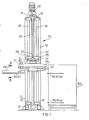
- the transfer apparatus 10 of this invention substantially comprises a supporting structure 11 which, in the case as shown in the figures of the accompanying drawings, is formed of a base frame 12 made of metal sections and a vertical pillar 13.
- This vertical pillar 13 has secured thereto two sliding guides which, in this exemplary embodiment, comprise two vertical uprights 15 and 16, respectively, attached for example by brackets 18 at the ends.
- a first vertical and rotable threaded stem 20 which is rotably driven by a geared motor unit 22, which is mounted on a top platform 23 of the supporting structure 11.
- a slider device 25 is slidably mounted on said sliding uprights 15 and 16 by means of two pairs of sleeves, one pair on each upright; the sleeves for upright 15 being indicated at 26, 26 and for those for upright 16 at 27, 27.
- the sleeves may be of any known form, for instance they will comprise brackets with sliding bearings.
- the slider device 25 further comprises a nut screw (non shown in the drawings) meshing on the threaded stem or screw 20 for the slider movement along uprights 15 and 16.
- a frame 29 is integral with the sleeves 26 and 27 and cantilever extends therefrom.
- This frame 29 of the slider device 25 carries second sliding guides in the form of cylindrical bars 31 and 32 extending at right angles to the first sliding guides 15 and 16; and carries therebetween a second threaded stem 33 (which is shown only in Fig. 6) that is rotably driven by a geared motor unit 34 (Fig. 2).
- a slide assembly 40 on the cylindrical bars 31 and 32 is slidably carried by two pairs of sleeves or brackets with bearings (of which one pair 38, 38 is shown in Fig. 2, and another sleeve 39 is shown in Fig. 6).
- This assembly 40 is better shown in Figs. 6 and 7 and is integral with a nut screw 41 meshing with threaded stem 33 for the slide movement along the guides 31 and 32.
- Said assembly or slide 40 comprises a top plate 42 integral with the sleeves 38 and 39 and threaded stem 33, and a pin 43 extending between said plate and having a bottom supporting plate 44 attached thereto, for example by screws 45.
- the rotational device 50 is mounted about said pin 43 and comprises a rotating body 51 mounted about pin 43 by two ball bearings 52 and 53.
- the cylindrical body 51 carries a driven gear wheel 55 meshing with a driving pinion 56 which, in turn, is driven by a geared motor unit 58 mounted on plate 42.
- said cylindrical body 51 widens out in a flange 51' and a roller thrust bearing 59 is interposed between said flange and said bottom plate 44.
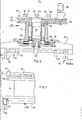
- a supporting framework comprising two parallel arms 61 and 62 is secured to said flange 51' of the rotating body.
- Each of the arms carry a sliding guide, generally in the form of a cylindrical bar, shown in the drawings at 63 and 64, respectively.
- a carriage 70 is slidably carried on bars 63 and 64 by means of sleeves 65 and 66 and associated brackets (Fig. 3) and in the particular embodiment shown comprises a quadrangular frame of sections.
- the sliding for carriage 70 is controlled by motor 71 (shown in Fig. 1).
- a rod holder head 72 is integral with carriage 70 and comprises a support or bearing 73 secured to carriage 70 and having two parallel cylindrical passages 74 and 75 to accomodate by bearings (generally bushings) 76 (see Figs. 4 and 5) respective parallel rotable spindles 77 and 78.
- Each of spindles 77 and 78 carry at one corresponding end a gear wheel 80 and 81, respectively, suitably secured, such as by pins.
- Each of the gear wheels mesh with a respective rack 82 and 83, the two racks being driven together through a fork 84 by a driving means, not shown in the drawings.
- each of the spindles 77 and 78 carry integrally therewith a supporting element 85 and 86, respectively, and each of the supporting elements carry by means of brackets 85' and 86' a rod indicated at 90 and 91, respectively.
- the rods 90 and 91 cantilever extend from the respective supporting elements and are parallel to each other. It will be also noted that, due to the particular assembly of the carrying elements, as above described, said rods 90 and 91 may be moved to or away (spread apart) from each other, while being always parallel to each other. Preferably, the adjustment between the racks and associated gear wheels is such that the rods are always in a horizontal plane.
- the rod carrying head is rectilinearly movable along three directions, of which two directions are at right angles to each other, while the third direction is perpendicular to the first direction, and can be also rotated through a desired angle about an axis parallel with the first direction of translation.
- rotational device may be placed at other locations of the machine.
- a widely used hank-carrier is shown at 100 of Fig. 1 and is somewhat hook shaped with a lower portion substantially planarly extending formed by two parallel small bars.
- Each of the carriers have one or more hanks hanging therefrom and each of the carriers are generally hooked or coupled to a chain or other moving means (not shown).
- a hank-carrier 100 to be unloaded moves along the transfer apparatus 10
- a movement of the carriage 70 along the bars 63 and 64 would introduce the ods 90 and 91, which are at the approached condition thereof of Figs.
- the rods 90 and 91 can be moved near each other. Then, the rotational device 50 is rotated, for example through an arc of 180°, so as to bring the rods to the hatched position shown at 90, 91 (a) in Figs. 1 and 6. Then, the operation of the geared motor 22 for the vertical movement and geared motors 34 and 71 for the horizontal movement in two orthogonal directions enables to lower the rod assembly (for example, to the position 90, 91(b) of Fig. 1) so as to arrange the hank at a desired position on a conveyor carriage 102 or conveyor belt (not shown) or on any other means. The rods are then slipped off from the hanks and the apparatus can start a new operation.
Landscapes
- Engineering & Computer Science (AREA)
- Textile Engineering (AREA)
- Specific Conveyance Elements (AREA)
- Manipulator (AREA)
- Replacing, Conveying, And Pick-Finding For Filamentary Materials (AREA)
- Tyre Moulding (AREA)
- Telephone Function (AREA)
- Auxiliary Devices For And Details Of Packaging Control (AREA)
- Confectionery (AREA)
Priority Applications (1)
| Application Number | Priority Date | Filing Date | Title |
|---|---|---|---|
| AT79102322T ATE4495T1 (de) | 1979-05-10 | 1979-07-09 | Stranguebertragungsvorrichtung. |
Applications Claiming Priority (2)
| Application Number | Priority Date | Filing Date | Title |
|---|---|---|---|
| IT2253179 | 1979-05-10 | ||
| IT22531/79A IT1166792B (it) | 1979-05-10 | 1979-05-10 | Apparecchio per trasferimento di matasse |
Publications (2)
| Publication Number | Publication Date |
|---|---|
| EP0019009A1 true EP0019009A1 (de) | 1980-11-26 |
| EP0019009B1 EP0019009B1 (de) | 1983-08-24 |
Family
ID=11197493
Family Applications (1)
| Application Number | Title | Priority Date | Filing Date |
|---|---|---|---|
| EP79102322A Expired EP0019009B1 (de) | 1979-05-10 | 1979-07-09 | Strangübertragungsvorrichtung |
Country Status (7)
| Country | Link |
|---|---|
| US (1) | US4281959A (de) |
| EP (1) | EP0019009B1 (de) |
| JP (1) | JPS55151468A (de) |
| AT (1) | ATE4495T1 (de) |
| CA (1) | CA1151688A (de) |
| DE (1) | DE2966087D1 (de) |
| IT (1) | IT1166792B (de) |
Cited By (1)
| Publication number | Priority date | Publication date | Assignee | Title |
|---|---|---|---|---|
| EP0126187A1 (de) * | 1982-12-31 | 1984-11-28 | OFFICINE MINNETTI di Federico Minnetti & C. S.A.S. | Mit einer Klinge versehenes Gerät zum Laden und Entladen von Strängen |
Families Citing this family (5)
| Publication number | Priority date | Publication date | Assignee | Title |
|---|---|---|---|---|
| IT1212409B (it) * | 1980-03-14 | 1989-11-22 | Raveggi Ornella Minnetti | Macchina per prelevare e scaricare matasse. |
| US4504186A (en) * | 1982-09-24 | 1985-03-12 | Braner Enterprises | Turret stacker |
| IT1263971B1 (it) * | 1993-07-16 | 1996-09-05 | Gd Spa | Apparecchiatura per il caricamento di bobine in una macchina confezionatrice. |
| US20040247423A1 (en) * | 2003-05-19 | 2004-12-09 | James Thiel | Multi-lift for lifting and storing motorcycles and other vehicles |
| CN110760957B (zh) * | 2018-07-25 | 2024-07-09 | 霍浦维(广东顺德)自动化设备有限公司 | 一种落筒机器人组 |
Citations (5)
| Publication number | Priority date | Publication date | Assignee | Title |
|---|---|---|---|---|
| GB366787A (en) * | 1931-03-28 | 1932-02-11 | John Clowes | Improvements in or relating to apparatus for the liquid treatment of textile yarns or threads |
| FR722149A (fr) * | 1930-10-31 | 1932-03-11 | Perfectionnements aux appareils pour faire tourner les écheveaux pendant la teinture, le finissage et les opérations analogues | |
| CH383909A (de) * | 1961-05-03 | 1964-11-15 | Schweiter Ag Maschf | Vorrichtung zum Öffnen von Garnstrangen |
| US3541635A (en) * | 1968-10-29 | 1970-11-24 | Riegel Textile Corp | Apparatus and method for random dyeing skeins of textile yarn |
| FR2057687A5 (de) * | 1969-08-25 | 1971-05-21 | Croon Lucke Maschinenfa |
Family Cites Families (2)
| Publication number | Priority date | Publication date | Assignee | Title |
|---|---|---|---|---|
| US2431618A (en) * | 1945-12-21 | 1947-11-25 | Western Electric Co | Conveyer |
| US3223267A (en) * | 1964-09-30 | 1965-12-14 | Crown Controls Corp | Lift truck |
-
1979
- 1979-05-10 IT IT22531/79A patent/IT1166792B/it active
- 1979-07-09 EP EP79102322A patent/EP0019009B1/de not_active Expired
- 1979-07-09 DE DE7979102322T patent/DE2966087D1/de not_active Expired
- 1979-07-09 AT AT79102322T patent/ATE4495T1/de active
- 1979-07-16 US US06/057,802 patent/US4281959A/en not_active Expired - Lifetime
- 1979-09-21 JP JP12093179A patent/JPS55151468A/ja active Granted
-
1980
- 1980-04-01 CA CA000349139A patent/CA1151688A/en not_active Expired
Patent Citations (5)
| Publication number | Priority date | Publication date | Assignee | Title |
|---|---|---|---|---|
| FR722149A (fr) * | 1930-10-31 | 1932-03-11 | Perfectionnements aux appareils pour faire tourner les écheveaux pendant la teinture, le finissage et les opérations analogues | |
| GB366787A (en) * | 1931-03-28 | 1932-02-11 | John Clowes | Improvements in or relating to apparatus for the liquid treatment of textile yarns or threads |
| CH383909A (de) * | 1961-05-03 | 1964-11-15 | Schweiter Ag Maschf | Vorrichtung zum Öffnen von Garnstrangen |
| US3541635A (en) * | 1968-10-29 | 1970-11-24 | Riegel Textile Corp | Apparatus and method for random dyeing skeins of textile yarn |
| FR2057687A5 (de) * | 1969-08-25 | 1971-05-21 | Croon Lucke Maschinenfa |
Cited By (1)
| Publication number | Priority date | Publication date | Assignee | Title |
|---|---|---|---|---|
| EP0126187A1 (de) * | 1982-12-31 | 1984-11-28 | OFFICINE MINNETTI di Federico Minnetti & C. S.A.S. | Mit einer Klinge versehenes Gerät zum Laden und Entladen von Strängen |
Also Published As
| Publication number | Publication date |
|---|---|
| EP0019009B1 (de) | 1983-08-24 |
| DE2966087D1 (en) | 1983-09-29 |
| JPS6116708B2 (de) | 1986-05-01 |
| IT1166792B (it) | 1987-05-06 |
| CA1151688A (en) | 1983-08-09 |
| ATE4495T1 (de) | 1983-09-15 |
| US4281959A (en) | 1981-08-04 |
| JPS55151468A (en) | 1980-11-26 |
| IT7922531A0 (it) | 1979-05-10 |
Similar Documents
| Publication | Publication Date | Title |
|---|---|---|
| US4958982A (en) | Device for transferring items | |
| US4809917A (en) | Automatic wire replacing system for use in an automatic wire coiling apparatus | |
| US4281959A (en) | Hank transfer apparatus | |
| KR20220128391A (ko) | 금속 와이어용 권선 모듈 및 권선 설비 | |
| US4391360A (en) | Machine for hank drawing and doffing | |
| US5738482A (en) | Apparatus for gripping and transporting slabs of great dimensions having feeding suckers | |
| US5938400A (en) | Loading and unloading apparatus, in particular for loading and unloading presses | |
| KR100211616B1 (ko) | 공간 수납 시스템에서의 바아 재료의 반송장치 및 이송방법 | |
| US4336875A (en) | Apparatus for the transfer of hanks | |
| EP0593805B1 (de) | Vorrichtung zur Herstellung einer Spule | |
| PL90978B1 (de) | ||
| EP0026272B1 (de) | Einrichtung für die Auspressung von Garnsträhnen und diesbezügliches Verfahren | |
| EP4194383B1 (de) | Automatisierte maschine zum abwickeln und aufwickeln von stoffspulen und verfahren zum abwickeln und aufwickeln einer mit dieser automatisierten maschine ausgeführten stoffspule | |
| EP0026256B1 (de) | Übergabevorrichtung für Garnstränge | |
| WO1999057052B1 (de) | Vorrichtung zur handhabung einer spule an einer spulmaschine | |
| CN114599594B (zh) | 棒材存储装置和方法 | |
| JP2005219833A (ja) | 自動倉庫の制御装置 | |
| EP0126187A1 (de) | Mit einer Klinge versehenes Gerät zum Laden und Entladen von Strängen | |
| JPH09111551A (ja) | 繊維機械、特にテクスチャリング機械による糸の加工処理後に、糸を巻いたボビンを取り出す装置 | |
| IT201900015168A1 (it) | Apparato e metodo per l'alimentazione di barre | |
| JPH05727A (ja) | 多段ラツクを有するパイプ搬送装置 | |
| JP3009113B2 (ja) | 材料貯蔵装置 | |
| JP2675211B2 (ja) | 表面処理装置 | |
| JP2546728B2 (ja) | テーピング完了品の収納箱自動供給装置 | |
| JPH0652733A (ja) | 巻取ボビンの自動処理装置 |
Legal Events
| Date | Code | Title | Description |
|---|---|---|---|
| PUAI | Public reference made under article 153(3) epc to a published international application that has entered the european phase |
Free format text: ORIGINAL CODE: 0009012 |
|
| AK | Designated contracting states |
Designated state(s): AT BE CH DE FR GB LU NL |
|
| 17P | Request for examination filed |
Effective date: 19810425 |
|
| GRAA | (expected) grant |
Free format text: ORIGINAL CODE: 0009210 |
|
| AK | Designated contracting states |
Designated state(s): AT BE CH DE FR GB LU NL |
|
| REF | Corresponds to: |
Ref document number: 4495 Country of ref document: AT Date of ref document: 19830915 Kind code of ref document: T |
|
| REF | Corresponds to: |
Ref document number: 2966087 Country of ref document: DE Date of ref document: 19830929 |
|
| ET | Fr: translation filed | ||
| RAP2 | Party data changed (patent owner data changed or rights of a patent transferred) |
Owner name: OFFICINE MINNETTI DI FEDERICO MINNETTI & C. S.A.S. |
|
| ET1 | Fr: translation filed ** revision of the translation of the patent or the claims | ||
| PLBE | No opposition filed within time limit |
Free format text: ORIGINAL CODE: 0009261 |
|
| STAA | Information on the status of an ep patent application or granted ep patent |
Free format text: STATUS: NO OPPOSITION FILED WITHIN TIME LIMIT |
|
| PGFP | Annual fee paid to national office [announced via postgrant information from national office to epo] |
Ref country code: CH Payment date: 19840710 Year of fee payment: 6 |
|
| PG25 | Lapsed in a contracting state [announced via postgrant information from national office to epo] |
Ref country code: LU Free format text: LAPSE BECAUSE OF NON-PAYMENT OF DUE FEES Effective date: 19840731 |
|
| PGFP | Annual fee paid to national office [announced via postgrant information from national office to epo] |
Ref country code: FR Payment date: 19840731 Year of fee payment: 6 |
|
| 26N | No opposition filed | ||
| PGFP | Annual fee paid to national office [announced via postgrant information from national office to epo] |
Ref country code: DE Payment date: 19840827 Year of fee payment: 6 |
|
| PGFP | Annual fee paid to national office [announced via postgrant information from national office to epo] |
Ref country code: BE Payment date: 19840930 Year of fee payment: 6 |
|
| PGFP | Annual fee paid to national office [announced via postgrant information from national office to epo] |
Ref country code: AT Payment date: 19860730 Year of fee payment: 8 |
|
| PGFP | Annual fee paid to national office [announced via postgrant information from national office to epo] |
Ref country code: NL Payment date: 19870731 Year of fee payment: 9 |
|
| PG25 | Lapsed in a contracting state [announced via postgrant information from national office to epo] |
Ref country code: GB Effective date: 19880709 Ref country code: AT Effective date: 19880709 |
|
| PG25 | Lapsed in a contracting state [announced via postgrant information from national office to epo] |
Ref country code: CH Effective date: 19880731 |
|
| PG25 | Lapsed in a contracting state [announced via postgrant information from national office to epo] |
Ref country code: NL Effective date: 19890201 |
|
| NLV4 | Nl: lapsed or anulled due to non-payment of the annual fee | ||
| GBPC | Gb: european patent ceased through non-payment of renewal fee | ||
| REG | Reference to a national code |
Ref country code: CH Ref legal event code: PL |
|
| PG25 | Lapsed in a contracting state [announced via postgrant information from national office to epo] |
Ref country code: DE Effective date: 19890401 |
|
| PG25 | Lapsed in a contracting state [announced via postgrant information from national office to epo] |
Ref country code: BE Effective date: 19890731 |
|
| BERE | Be: lapsed |
Owner name: OFFICINE MINNETTI DI FREDERICO MINNETTI & C. S.A. Effective date: 19890731 |
|
| PG25 | Lapsed in a contracting state [announced via postgrant information from national office to epo] |
Ref country code: FR Free format text: LAPSE BECAUSE OF NON-PAYMENT OF DUE FEES Effective date: 19900330 |
|
| REG | Reference to a national code |
Ref country code: FR Ref legal event code: ST |