EP0019018B1 - Outils à aléser - Google Patents
Outils à aléser Download PDFInfo
- Publication number
- EP0019018B1 EP0019018B1 EP19790300806 EP79300806A EP0019018B1 EP 0019018 B1 EP0019018 B1 EP 0019018B1 EP 19790300806 EP19790300806 EP 19790300806 EP 79300806 A EP79300806 A EP 79300806A EP 0019018 B1 EP0019018 B1 EP 0019018B1
- Authority
- EP
- European Patent Office
- Prior art keywords
- blades
- blade
- rotation
- axis
- worm
- Prior art date
- Legal status (The legal status is an assumption and is not a legal conclusion. Google has not performed a legal analysis and makes no representation as to the accuracy of the status listed.)
- Expired
Links
- 230000001154 acute effect Effects 0.000 claims description 3
- 230000037431 insertion Effects 0.000 claims 1
- 238000003780 insertion Methods 0.000 claims 1
- 238000005553 drilling Methods 0.000 description 3
- 238000004519 manufacturing process Methods 0.000 description 1
- 230000000717 retained effect Effects 0.000 description 1
Images
Classifications
-
- B—PERFORMING OPERATIONS; TRANSPORTING
- B23—MACHINE TOOLS; METAL-WORKING NOT OTHERWISE PROVIDED FOR
- B23B—TURNING; BORING
- B23B29/00—Holders for non-rotary cutting tools; Boring bars or boring heads; Accessories for tool holders
- B23B29/03—Boring heads
- B23B29/034—Boring heads with tools moving radially, e.g. for making chamfers or undercuttings
- B23B29/03432—Boring heads with tools moving radially, e.g. for making chamfers or undercuttings radially adjustable during manufacturing
- B23B29/03446—Boring heads with tools moving radially, e.g. for making chamfers or undercuttings radially adjustable during manufacturing by means of inclined planes
Definitions
- This invention relates to boring tools in which the cutting diameter can be adjusted. It has been proposed in US-A-3256755 to provide a boring tool comprising a body supporting outwardly extending cutting blades and housing blade advancing means for moving the blades outwardly or inwardly to adjust the cutting diameter.
- the blades are mounted in guides screwed into holes in the body and the blade advancing member is linearly movable through a gear train comprising a worm and a worm wheel, the worm wheel being axially fixed and having an internal thread engaging an external thread on a spindle part of the blade advancing member.
- This blade advancing member has four planar sides provided with slideways for guiding shoes or wedging cams for transmitting adjustment movement to the blades from the blade advancing member.
- the blades can only be adjusted in position via a number of cooperating drive surfaces.
- FR-A-919069 discloses a boring tool in which the blades have planar side faces slidably located by cooperating faces of recesses in the tool body and in which the blade advancing member has a helical threaded shank engaged by two screws which are rotatable to displace the member and hence the blades.
- This boring tool also requires the use of a considerable number of drive and bearing surfaces which can wear and reduce accuracy.
- a boring tool comprising a body supporting a plurality of cutting blades such that the blades are movable along paths equally inclined at an acute angle to an axis of rotation of the body, the outer ends of the blades having cutting edges and projecting beyond the body, and a blade advancing member within the body for carrying a head within a cavity in the body having a screwed shaft and being located within a bore coaxial with the axis of rotation of the body, the head being in use in contact with the inner ends of the cutting blades and meshing with a worm within the body on an axis at right angles to the axis of rotation and being rotatable from outside the body so as to rotate the worm wheel to advance or retract the blade advancing member, characterised in that each blade is of constant cross-section along substantially its entire length, and is located and slidable within a surrounding cylindrical hole extending through the wall of the body surrounding the cavity, the blade advancing member is provided with a single conical blade contacting surface and is rot
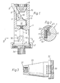
- the tool shown in Figures 1 and 2 of the drawings comprises a cylindrical body 1 which comprises a ring nut 2 at one end, for mounting in an adaptor to be later described so that the tool may be connected to a chuck or drive means of a drilling or boring machine for rotation about its cylindrical axis.
- a bore 4 extends longitudinally through the body and is widened at the other end 3 of the body to form a cylindrical cavity 5.
- a plurality of cylindrical holes 6 of circular cross-section are formed at the end 3 of the body through the cavity wall, each hole lying at an acute angle to the body axis.
- the holes are equispaced to form slideways for at least three or four cutter blades 7 (only one being shown in Figure 1) which are retained by a screwed end plug 8 which backs a pressure pad 19 within the cavity and having a coned surface to guide the blades.
- the outer ends of the blades, which project beyond the body are ground to provide cutting edges and the inner ends 10 of the blades abut a conical surface of a head 11 of a blade advancing member 12.
- each has a longitudinal flat formed on its surface to engage the coned surface of the pressure pad.
- the head 11 of the member 12 is carried on one end of a screwed shank 13 mounted within a threaded portion 14 of the bore 4.
- the other end of the shank carries a square-section shaft 15 having a diagonal dimension less than the bore diameter.
- the shank carries a worm wheel 16 slidable thereon and meshing with a worm 17 rotatably carried in an open ended drilling 20 in the body on an axis at right-angles to the axis of rotation of the body.
- the worm has a socket 18 in its spindle to receive a removable key (not shown) by means of which it can be rotated.
- To locate the worm axially the drilling has a shoulder 21 at one end and is provided with a bush 22 at the other end secured by a retainer 23.
- Rotation of the worm by the key causes corresponding rotation of the worm wheel, and thus the shaft of the member 12 resulting in axial movement of the head 11 to advance or retract the blades equally.
- the diameter of a hole cut by the blades during rotation of the tool can be adjusted accurately and to within fine limits.
- the shank 13 is screwed with a pitch of 1.25 mm
- the worm wheel has 25 teeth and the worm is threaded at a pitch of 1.25 mm.
- one complete rotation of the worm causes a variation in the blade setting diameter of 0.635 mm so that a variation of as little as 0.00635 mm can be achieved.
- the worm gearing produces a mechanical advantage which locks the setting and prevents a loss of adjustment when the teeth are under load.
- biassing means such as springs can be incorporated to urge the blades inwardly.
- the tool adapter 30 as shown in Figure 3 is largely of frusto-conical shape and at its smaller end 31 is internally threaded for mounting on the shaft of a power tool.
- the surface 32 of the adapter is of cylindrical shape and is screw threaded to engage a ring nut 2 on the tool.
- a knurled or serrated spigot 34 on the tool engages within a similarly knurled or serrated cylindrical recess 36 in the end 32 of the adaptor to provide a positive rotational drive from the adaptor to the tool.
Landscapes
- Engineering & Computer Science (AREA)
- Mechanical Engineering (AREA)
- Cutting Tools, Boring Holders, And Turrets (AREA)
- Drilling Tools (AREA)
Claims (4)
Priority Applications (2)
| Application Number | Priority Date | Filing Date | Title |
|---|---|---|---|
| EP19790300806 EP0019018B1 (fr) | 1979-05-10 | 1979-05-10 | Outils à aléser |
| DE7979300806T DE2967325D1 (en) | 1979-05-10 | 1979-05-10 | Boring tools |
Applications Claiming Priority (1)
| Application Number | Priority Date | Filing Date | Title |
|---|---|---|---|
| EP19790300806 EP0019018B1 (fr) | 1979-05-10 | 1979-05-10 | Outils à aléser |
Publications (2)
| Publication Number | Publication Date |
|---|---|
| EP0019018A1 EP0019018A1 (fr) | 1980-11-26 |
| EP0019018B1 true EP0019018B1 (fr) | 1984-12-12 |
Family
ID=8186371
Family Applications (1)
| Application Number | Title | Priority Date | Filing Date |
|---|---|---|---|
| EP19790300806 Expired EP0019018B1 (fr) | 1979-05-10 | 1979-05-10 | Outils à aléser |
Country Status (2)
| Country | Link |
|---|---|
| EP (1) | EP0019018B1 (fr) |
| DE (1) | DE2967325D1 (fr) |
Families Citing this family (5)
| Publication number | Priority date | Publication date | Assignee | Title |
|---|---|---|---|---|
| IT1198791B (it) * | 1984-02-23 | 1988-12-21 | Bakuer Italiana Spa | Dispositivo per la registrazione automatica dell'utensile sul portautensile montato sul mandrino di una macchina utensile,senza rimuoverlo dal portautensile ed usufruendo della rotazione del detto mandrino |
| DE3417450A1 (de) * | 1984-05-11 | 1985-11-21 | Erowa Ag, Reinach | Werkzeuganordnung |
| DE3510375A1 (de) * | 1985-03-22 | 1986-09-25 | Robert Bosch Gmbh, 7000 Stuttgart | Werkzeug zur herstellung hinterschnittener bohrloecher |
| US5449671A (en) * | 1993-09-29 | 1995-09-12 | Alcon Laboratories, Inc. | Use of TGF-β3, to prevent or retard fistula closure following glaucoma filtration surgery |
| GB0321264D0 (en) * | 2003-09-11 | 2003-10-08 | Cogsdill Nuneaton Ltd | Head and holder for a rotary cutting etc and/or burnishing tool |
Family Cites Families (5)
| Publication number | Priority date | Publication date | Assignee | Title |
|---|---|---|---|---|
| FR759981A (fr) * | 1933-08-07 | 1934-02-14 | Dispositif de tête porte-outils d'alésage | |
| FR919069A (fr) * | 1945-12-17 | 1947-02-26 | Nat Acme Co | Outils d'alésage ou de rectification intérieure |
| US2712686A (en) * | 1954-05-18 | 1955-07-12 | Ex Cell O Corp | Adjustable tool construction |
| US3256755A (en) * | 1962-04-30 | 1966-06-21 | Edouard Meyer | Adjustable boring head |
| FR1580843A (fr) * | 1968-01-02 | 1969-09-12 |
-
1979
- 1979-05-10 EP EP19790300806 patent/EP0019018B1/fr not_active Expired
- 1979-05-10 DE DE7979300806T patent/DE2967325D1/de not_active Expired
Also Published As
| Publication number | Publication date |
|---|---|
| EP0019018A1 (fr) | 1980-11-26 |
| DE2967325D1 (en) | 1985-01-24 |
Similar Documents
| Publication | Publication Date | Title |
|---|---|---|
| US3645640A (en) | Rotary cutter tool | |
| EP2467225B1 (fr) | Dispositif d'usinage d'extrémité de tube présentant un entraînement axial automatique | |
| US5054968A (en) | Mechanical positive feed drill with supported spindle | |
| US2365549A (en) | Grooving tool | |
| US2247283A (en) | Boring tool | |
| EP0019018B1 (fr) | Outils à aléser | |
| CA1219118A (fr) | Outil de coupe a reglage de precision | |
| US4538943A (en) | Adjustable nosepiece for a drill motor | |
| US4627773A (en) | Right angle spindle for machine tools | |
| WO1990005606A1 (fr) | Porte-outil reglable | |
| US4018542A (en) | Adjustable tool holder for boring bar | |
| US2330692A (en) | Boring tool | |
| US4260303A (en) | Boring tools | |
| US4761103A (en) | Micro-adjustable boring head | |
| JPH01306124A (ja) | 全ての公知のねじを一工程で製造するための装置及び工具 | |
| US3664755A (en) | Finishing boring head | |
| US3146641A (en) | Recessing tool | |
| US4204784A (en) | Tools for reconditioning a valve seat in a tap | |
| US4544309A (en) | Adjustable cutting or boring tool | |
| US3143902A (en) | Drilling assembly | |
| JPS594243B2 (ja) | 切削刃具角度補正装置付加工ヘツド | |
| US4164381A (en) | Facing and grooving tool | |
| US2847882A (en) | Recessing tool | |
| EP0095240A2 (fr) | Porte-outils | |
| CN114012124A (zh) | 一种具有吸尘功能的机械加工用快速钻孔装置 |
Legal Events
| Date | Code | Title | Description |
|---|---|---|---|
| PUAI | Public reference made under article 153(3) epc to a published international application that has entered the european phase |
Free format text: ORIGINAL CODE: 0009012 |
|
| AK | Designated contracting states |
Designated state(s): CH DE FR IT NL SE |
|
| 17P | Request for examination filed |
Effective date: 19810325 |
|
| GRAA | (expected) grant |
Free format text: ORIGINAL CODE: 0009210 |
|
| AK | Designated contracting states |
Designated state(s): CH DE FR IT NL SE |
|
| PG25 | Lapsed in a contracting state [announced via postgrant information from national office to epo] |
Ref country code: SE Effective date: 19841212 Ref country code: NL Effective date: 19841212 Ref country code: IT Free format text: LAPSE BECAUSE OF FAILURE TO SUBMIT A TRANSLATION OF THE DESCRIPTION OR TO PAY THE FEE WITHIN THE PRESCRIBED TIME-LIMIT;WARNING: LAPSES OF ITALIAN PATENTS WITH EFFECTIVE DATE BEFORE 2007 MAY HAVE OCCURRED AT ANY TIME BEFORE 2007. THE CORRECT EFFECTIVE DATE MAY BE DIFFERENT FROM THE ONE RECORDED. Effective date: 19841212 Ref country code: FR Free format text: THE PATENT HAS BEEN ANNULLED BY A DECISION OF A NATIONAL AUTHORITY Effective date: 19841212 Ref country code: CH Effective date: 19841212 |
|
| REF | Corresponds to: |
Ref document number: 2967325 Country of ref document: DE Date of ref document: 19850124 |
|
| REG | Reference to a national code |
Ref country code: CH Ref legal event code: PL |
|
| NLV1 | Nl: lapsed or annulled due to failure to fulfill the requirements of art. 29p and 29m of the patents act | ||
| EN | Fr: translation not filed | ||
| PLBE | No opposition filed within time limit |
Free format text: ORIGINAL CODE: 0009261 |
|
| STAA | Information on the status of an ep patent application or granted ep patent |
Free format text: STATUS: NO OPPOSITION FILED WITHIN TIME LIMIT |
|
| 26N | No opposition filed | ||
| PG25 | Lapsed in a contracting state [announced via postgrant information from national office to epo] |
Ref country code: DE Effective date: 19860201 |