EP0019019B1 - Dispositif limiteur de couple pour clé à douille - Google Patents
Dispositif limiteur de couple pour clé à douille Download PDFInfo
- Publication number
- EP0019019B1 EP0019019B1 EP79300809A EP79300809A EP0019019B1 EP 0019019 B1 EP0019019 B1 EP 0019019B1 EP 79300809 A EP79300809 A EP 79300809A EP 79300809 A EP79300809 A EP 79300809A EP 0019019 B1 EP0019019 B1 EP 0019019B1
- Authority
- EP
- European Patent Office
- Prior art keywords
- clutch
- housing
- torque
- ring
- socket
- Prior art date
- Legal status (The legal status is an assumption and is not a legal conclusion. Google has not performed a legal analysis and makes no representation as to the accuracy of the status listed.)
- Expired
Links
Images

Classifications
-
- B—PERFORMING OPERATIONS; TRANSPORTING
- B25—HAND TOOLS; PORTABLE POWER-DRIVEN TOOLS; MANIPULATORS
- B25B—TOOLS OR BENCH DEVICES NOT OTHERWISE PROVIDED FOR, FOR FASTENING, CONNECTING, DISENGAGING, OR HOLDING
- B25B23/00—Details of, or accessories for, spanners, wrenches, screwdrivers
- B25B23/14—Arrangement of torque limiters or torque indicators in wrenches or screwdrivers
- B25B23/142—Arrangement of torque limiters or torque indicators in wrenches or screwdrivers specially adapted for hand operated wrenches or screwdrivers
Definitions
- This invention relates to a device for a torque wrench for coupling a torque handle to a socket.
- the conventional torque wrench is generally provided with no torque indicating means and is prone to distorting or breaking a nut of an article when the torsion applied thereto is too great. Conversely, the nut loosens and becomes insecure when the torque applied is insufficient. For example, spark plugs and various nuts and bolts used in automobiles and motorcycles, and fittings for home electrical appliances require tightening to a specific torque value.
- torque wrench has an indicating disc on a handle thereof and an indicator on a rectangular plug thereof.
- it is considerably bulky and is inconvenient to use.
- it requires close attention to be paid to the indicating disc and the indicator thereof while being used to ensure that the desired torque is not exceeded. In this case, only a skilled operator can make good use of the torque wrench.
- United States Patent Specification No. 3,889,490 describes a simple form of torque wrench which is locked by means of a screw.
- United States Patent Specification No. 3,001,430 describes a torque limiting screwdriver with a ball detent mechanism arranged to transmit the torque force.
- An object of the present invention is to provide an improved socket joint for a torque wrench.
- the present invention provides a torque limiting device for a socket wrench comprising a torque limiting clutch for transmitting torque from the socket wrench to a socket, the clutch comprising two frictionally engaged clutch members; resilient means applying force to one of the clutch members to maintain said clutch members in engagement with one another, said force being adjustable; control means movable between a first position wherein said force is fixed and a second position enabling adjustment of said force; a substantially tubular housing telescopically engaged in a substantially tubular portion of a body and containing said torque limiting clutch for transmitting torque from the socket wrench to a socket, one of the clutch members being adapted for engagement in the socket and the other being coupled to said body by way of said resilient means, whereby rotation of said housing relative to said body adjusts said force applied by said means characterised in that said body is connectible at its end remote from said housing to said socket wrench and said control means comprises a controlling ring coaxially surrounding said body and rotatable relative thereto between said first and second positions, at least one torque transmitting ball element movably
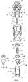
- Figure 1 shows a preferred device according to this invention comprising a body 10, a bolt 20, a rectangular plug 60, a clutch housing in the form of a casing 50, a clutch 70, a spring 80, a compressing ring 40, a controlling ring 30 in the form of a sleeve-like member and a positioning nut 90.
- the body 10 is in the form of a cylinder having a cylindrical portion or chamber 11 situated at its lower end as seen in Fig. 1 so as to receive the clutch casing 50. Situated adjacent the opposite, upper end of the chamber 11 is a screw-threaded axial blind bore 12 which engages with one end of the bolt 20. A plurality of small screw-threaded radial bores 13 is provided in the body 10 opening into the bore 12 for receiving screws 25 which secure the bolt 20 in position. A plurality of through holes 16 are provided in the wall 15 of the chamber 11 so as to receive a plurality torque transmitting elements in the form of balls 17 each having a diameter greater than the thickness of the wall 15 of the chamber 11.
- the upper end of the body 10 is provided with an axial socket 18 of rectangular cross-section so as to receive a rectangular plug of a torque wrench (not shown).
- the outer periphery of the body 10 is engraved with a plurality of lines 19 (Figs. 4 and 5) corresponding in number to recesses in the form of guiding flutes 53 of the clutch casing 50 and indicating lines and symbols 55 engraved on the outer wall of the casing 50.
- One end of the bolt 20 engages in the bore 12 as described above; the other end thereof engages in a screw threaded axial bore 93 in the positioning nut 90.
- the controlling ring 30 is a sleeve-like fit around the outer wall of the chamber 11 and at each end has a respective annular recess 31, 32 in the form of increased internal diameter portions so as to protect wholly the compressing ring 40 and the outer wall of the body 10 in part.
- a protruding pin 33 is provided on the controlling ring 30 and engages in an arcuate groove 42 in an upper surface 41 of the compressing ring 40 so that rotation of the controlling ring 30 relative to the ring 40 is limited.
- the outer wall of the controlling ring 30 is provided with an indicating means 34 (Figs. 4 and 5) showing the states of "ON" and "OFF” each of which can be brought into alignment with an arrow on the body 10 to indicate whether torsion is "ON" or "OFF".
- the inner wall 35 of the ring 30 is provided with a plurality of longitudinal grooves 36 to receive the balls 17. A slanting rim of each groove 36 facilitates insertion and removal of said balls 17.
- the inner diameter of the compressing ring 40 is equal to the outer diameter of the wall 15 so that said compressing ring 40 is a tight fit over the body 10.
- the outer diameter of the ring 40 is somewhat smaller than inner diameter of the recess 32 of the ring 30 so as to enable the controlling ring 30 to rotate freely.
- the clutch casing 50 is a hollow cylindrical tube provided with a radially inwardly directed annular flange 51 at a lower end of its inner wall to receive the rectangular plug 60 and clutch 70.
- the positioning nut 90 is secured to the clutch casing 50 by inserting one or more pins 95 through holes 52 and 92 in the casing 50 and positioning nut 90 respectively.
- the spring 80 is positioned between the bolt 20 and clutch 70.
- a plurality of guiding flutes 53 are provided on the outer wall of the casing 50 so as to partially receive the balls 17.
- a plurality of indicating lines and symbols 55 are engraved on the outer wall thereof to indicate the strength of the torque applied thereto.
- the plug 60 rests against the protruding ring 51 with its rectangular portion projecting at one end and is designed to connect with a socket of an article.
- the other end of the plug 60 is formed as one clutch member 701 with teeth to engage with teeth 71 on a second clutch member 702.
- the clutch members 701, 702 as shown in Figure 1 have symmetrical teeth.
- Figure 6 shows a further preferred embodiment of the clutch; one contacting face thereof is provided with a plurality of protrusions 711 while another face thereof is provided with several cavities 712 corresponding to the protrusions 711.
- a locating means 72 is situated to position said spring 80 on the clutch.
- the positioning nut 90 has a cylindrical outer wall 91 provided with two said circular holes 92 to enable it to be secured to the clutch casing 50 as described hereinbefore.
- the inner wall of the nut 90 is provided with the bore 93 as previously mentioned permitting movement of the clutch casing 50 with respect to the body 10 so as to adjust the tension of the spring 80 and to adjust the torque applied by the socket joint.
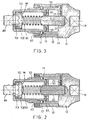
- FIGs 2, 3 and 4 show how the socket joint of this invention is fitted to a torque wrench.
- a plug of a torque wrench 100 is inserted in the rectangular socket 18.
- the rectangular plug 60 then engages with a socket of an article requiring torque.
- the controlling ring 30 is rotated to the indicating means 34 to bring the "OFF" indicating means 34 adjacent the arrow on the body 10 the balls 17 which are held in engagement in the flutes 53 by the inner wall of the ring 30 will engage in the grooves 36 of the controlling ring 30. This allows the balls to rise out of the flutes 53 (Fig. 2) and allows rotation of the body 10 relative to the casing 50.
- Rotating the body 10 relative to the casing 50 screws the bolt 20 into or out of the positioning nut 90 thus drawing the casing 50 into or out of the body 10 and adjusting the force of the spring 80 acting on the clutch member 702.
- Torque is indicated by the lines and symbols 55 and 19 engraved on the clutch casing 50 and body 10.
- the controlling ring 30 is then rotated to bring the "ON" indicating means 34 adjacent the arrow on the body 10 to force the balls 17 into the guiding flutes 53 and hold them in position to prevent relative rotation of the body 10 and casing 50 (as shown in Figure 2).
- the force of the spring 80 is such that while the set torque is not exceeded the clutch members will be held in engagement. Once the torque is exceeded the teeth on the members 701, 702 will ride over one another.
- the pre-decided amount of the torque may be changed if need be.
- the socket joint of this invention is also applicable to a non-ratchet type torque wrench handle 200 as shown in Figure 5.
Landscapes
- Engineering & Computer Science (AREA)
- Mechanical Engineering (AREA)
- Details Of Spanners, Wrenches, And Screw Drivers And Accessories (AREA)
- Snaps, Bayonet Connections, Set Pins, And Snap Rings (AREA)
Claims (11)
Priority Applications (4)
| Application Number | Priority Date | Filing Date | Title |
|---|---|---|---|
| EP79300809A EP0019019B1 (fr) | 1979-05-11 | 1979-05-11 | Dispositif limiteur de couple pour clé à douille |
| DE7979300809T DE2965839D1 (en) | 1979-05-11 | 1979-05-11 | Device for a torque wrench |
| AT79300809T ATE4096T1 (de) | 1979-05-11 | 1979-05-11 | Vorrichtung fuer schraubenschluessel. |
| DE197979300809T DE19019T1 (de) | 1979-05-11 | 1979-05-11 | Vorrichtung fuer schraubenschluessel. |
Applications Claiming Priority (1)
| Application Number | Priority Date | Filing Date | Title |
|---|---|---|---|
| EP79300809A EP0019019B1 (fr) | 1979-05-11 | 1979-05-11 | Dispositif limiteur de couple pour clé à douille |
Publications (2)
| Publication Number | Publication Date |
|---|---|
| EP0019019A1 EP0019019A1 (fr) | 1980-11-26 |
| EP0019019B1 true EP0019019B1 (fr) | 1983-07-13 |
Family
ID=8186372
Family Applications (1)
| Application Number | Title | Priority Date | Filing Date |
|---|---|---|---|
| EP79300809A Expired EP0019019B1 (fr) | 1979-05-11 | 1979-05-11 | Dispositif limiteur de couple pour clé à douille |
Country Status (3)
| Country | Link |
|---|---|
| EP (1) | EP0019019B1 (fr) |
| AT (1) | ATE4096T1 (fr) |
| DE (2) | DE2965839D1 (fr) |
Cited By (1)
| Publication number | Priority date | Publication date | Assignee | Title |
|---|---|---|---|---|
| US11878393B2 (en) | 2020-10-09 | 2024-01-23 | Milwaukee Electric Tool Corporation | Clutch socket adapter for a tool |
Families Citing this family (5)
| Publication number | Priority date | Publication date | Assignee | Title |
|---|---|---|---|---|
| GB8729687D0 (en) * | 1987-12-21 | 1988-02-03 | Mcauley C H | Spanners |
| DE102006032812B4 (de) * | 2005-08-19 | 2012-06-21 | Chia-Chiung Chuang | Übertragungselement mit Drehmoment begrenzender Schutzstruktur |
| WO2015109191A1 (fr) | 2014-01-17 | 2015-07-23 | DePuy Synthes Products, Inc. | Instrument de restriction de couple |
| TWI649166B (zh) | 2014-01-17 | 2019-02-01 | 美商德派信迪思產品公司 | 扭矩限制器具(二) |
| CN108562390B (zh) * | 2018-05-23 | 2024-05-14 | 兴机电器集团有限公司 | 断路器底盘车定扭矩摇把 |
Family Cites Families (5)
| Publication number | Priority date | Publication date | Assignee | Title |
|---|---|---|---|---|
| DE1254549B (de) * | 1955-02-07 | 1967-11-16 | Licentia Gmbh | Elektrowerkzeug mit einer zum Loesen von Einsteckwerkzeugen axial verschiebbaren Muffe und einer Rutschkupplung mit Feder |
| US3001430A (en) * | 1958-12-22 | 1961-09-26 | James W Cranford | Predetermined torque release tool |
| US3442360A (en) * | 1967-10-04 | 1969-05-06 | Charles Fulop | Power operated,predetermined torque release,bolt driver |
| US3889490A (en) * | 1974-05-16 | 1975-06-17 | Felix J Nadolny | Torque control adaptor for ratchet wrench |
| US3942337A (en) * | 1974-09-16 | 1976-03-09 | Industrial Analytics Inc. | Torque limiting device |
-
1979
- 1979-05-11 DE DE7979300809T patent/DE2965839D1/de not_active Expired
- 1979-05-11 AT AT79300809T patent/ATE4096T1/de active
- 1979-05-11 DE DE197979300809T patent/DE19019T1/de active Pending
- 1979-05-11 EP EP79300809A patent/EP0019019B1/fr not_active Expired
Cited By (1)
| Publication number | Priority date | Publication date | Assignee | Title |
|---|---|---|---|---|
| US11878393B2 (en) | 2020-10-09 | 2024-01-23 | Milwaukee Electric Tool Corporation | Clutch socket adapter for a tool |
Also Published As
| Publication number | Publication date |
|---|---|
| DE19019T1 (de) | 1983-04-14 |
| DE2965839D1 (en) | 1983-08-18 |
| EP0019019A1 (fr) | 1980-11-26 |
| ATE4096T1 (de) | 1983-07-15 |
Similar Documents
| Publication | Publication Date | Title |
|---|---|---|
| US4272973A (en) | Socket joint for torque wrench | |
| US5230142A (en) | Operating and torque tool | |
| US6045303A (en) | Rotatable torque adjusting device of rotation tool | |
| US4775269A (en) | Hand held tool with removable chuck | |
| US7000709B2 (en) | Side handles on drill/drivers | |
| US4846027A (en) | Screwdriver | |
| US4346633A (en) | Spark plug wrench adapted for adjustable torque | |
| US4121444A (en) | Manually operable tool for installing blind anchor nuts | |
| US4619437A (en) | Adjustable torque limiting valve handle | |
| US6047801A (en) | Ratchet screwdriver | |
| US5795116A (en) | Arrangement in a rotatable device to protect against over-tightening | |
| US5195761A (en) | Chuck for tool inserts, especially screwdriver bits | |
| CN207014254U (zh) | 具锁定及释放功能的扭力套筒 | |
| TWM551552U (zh) | 具鎖定及釋放功能的扭力套筒 | |
| US4682395A (en) | Device for pushing wheel flange hubs and splined flange hubs of motor vehicles out of a shaft bearing | |
| TWM598760U (zh) | 扭力套筒 | |
| GB2173729A (en) | Tool for screw threaded fasteners | |
| US6085619A (en) | Tool bit adapter for universal socket tool | |
| JPS6047047B2 (ja) | タツプホルダ | |
| US10702979B2 (en) | Torque adjustment device for torque wrench | |
| US4934221A (en) | Apparatus for retaining a replaceable tool head on a T-handle-type wrench | |
| EP0019019A1 (fr) | Dispositif limiteur de couple pour clé à douille | |
| JPS5831500B2 (ja) | 緊張装置 | |
| US5442980A (en) | Nut drive adapter | |
| US2439980A (en) | Limited torque tool |
Legal Events
| Date | Code | Title | Description |
|---|---|---|---|
| PUAI | Public reference made under article 153(3) epc to a published international application that has entered the european phase |
Free format text: ORIGINAL CODE: 0009012 |
|
| 17P | Request for examination filed | ||
| AK | Designated contracting states |
Designated state(s): AT BE CH DE FR GB IT LU NL SE |
|
| ITF | It: translation for a ep patent filed | ||
| DET | De: translation of patent claims | ||
| GRAA | (expected) grant |
Free format text: ORIGINAL CODE: 0009210 |
|
| AK | Designated contracting states |
Designated state(s): AT BE CH DE FR GB IT LU NL SE |
|
| REF | Corresponds to: |
Ref document number: 4096 Country of ref document: AT Date of ref document: 19830715 Kind code of ref document: T |
|
| REF | Corresponds to: |
Ref document number: 2965839 Country of ref document: DE Date of ref document: 19830818 |
|
| ET | Fr: translation filed | ||
| PGFP | Annual fee paid to national office [announced via postgrant information from national office to epo] |
Ref country code: FR Payment date: 19840327 Year of fee payment: 6 |
|
| PGFP | Annual fee paid to national office [announced via postgrant information from national office to epo] |
Ref country code: CH Payment date: 19840510 Year of fee payment: 6 |
|
| PLBE | No opposition filed within time limit |
Free format text: ORIGINAL CODE: 0009261 |
|
| STAA | Information on the status of an ep patent application or granted ep patent |
Free format text: STATUS: NO OPPOSITION FILED WITHIN TIME LIMIT |
|
| PGFP | Annual fee paid to national office [announced via postgrant information from national office to epo] |
Ref country code: DE Payment date: 19840525 Year of fee payment: 6 |
|
| PG25 | Lapsed in a contracting state [announced via postgrant information from national office to epo] |
Ref country code: LU Free format text: LAPSE BECAUSE OF NON-PAYMENT OF DUE FEES Effective date: 19840531 |
|
| PGFP | Annual fee paid to national office [announced via postgrant information from national office to epo] |
Ref country code: SE Payment date: 19840630 Year of fee payment: 6 Ref country code: BE Payment date: 19840630 Year of fee payment: 6 |
|
| 26N | No opposition filed | ||
| PGFP | Annual fee paid to national office [announced via postgrant information from national office to epo] |
Ref country code: AT Payment date: 19850521 Year of fee payment: 7 |
|
| PGFP | Annual fee paid to national office [announced via postgrant information from national office to epo] |
Ref country code: NL Payment date: 19850531 Year of fee payment: 7 |
|
| PG25 | Lapsed in a contracting state [announced via postgrant information from national office to epo] |
Ref country code: AT Effective date: 19860511 |
|
| PG25 | Lapsed in a contracting state [announced via postgrant information from national office to epo] |
Ref country code: SE Effective date: 19860512 |
|
| PG25 | Lapsed in a contracting state [announced via postgrant information from national office to epo] |
Ref country code: CH Effective date: 19860531 Ref country code: BE Effective date: 19860531 |
|
| BERE | Be: lapsed |
Owner name: FU-TSAI LEE Effective date: 19860531 |
|
| PG25 | Lapsed in a contracting state [announced via postgrant information from national office to epo] |
Ref country code: NL Effective date: 19861201 |
|
| NLV4 | Nl: lapsed or anulled due to non-payment of the annual fee | ||
| GBPC | Gb: european patent ceased through non-payment of renewal fee | ||
| PG25 | Lapsed in a contracting state [announced via postgrant information from national office to epo] |
Ref country code: FR Free format text: LAPSE BECAUSE OF NON-PAYMENT OF DUE FEES Effective date: 19870130 |
|
| REG | Reference to a national code |
Ref country code: CH Ref legal event code: PL |
|
| PG25 | Lapsed in a contracting state [announced via postgrant information from national office to epo] |
Ref country code: DE Effective date: 19870203 |
|
| REG | Reference to a national code |
Ref country code: FR Ref legal event code: ST |
|
| PG25 | Lapsed in a contracting state [announced via postgrant information from national office to epo] |
Ref country code: GB Effective date: 19881118 |
|
| EUG | Se: european patent has lapsed |
Ref document number: 79300809.5 Effective date: 19870225 |