EP0019105A2 - Procédé d'adsorption en cycle continu et son emploi pour la production d'acides organiques - Google Patents
Procédé d'adsorption en cycle continu et son emploi pour la production d'acides organiques Download PDFInfo
- Publication number
- EP0019105A2 EP0019105A2 EP80102162A EP80102162A EP0019105A2 EP 0019105 A2 EP0019105 A2 EP 0019105A2 EP 80102162 A EP80102162 A EP 80102162A EP 80102162 A EP80102162 A EP 80102162A EP 0019105 A2 EP0019105 A2 EP 0019105A2
- Authority
- EP
- European Patent Office
- Prior art keywords
- gas
- phase
- oxygen
- desorption
- pressure
- Prior art date
- Legal status (The legal status is an assumption and is not a legal conclusion. Google has not performed a legal analysis and makes no representation as to the accuracy of the status listed.)
- Granted
Links
Images


Classifications
-
- B—PERFORMING OPERATIONS; TRANSPORTING
- B01—PHYSICAL OR CHEMICAL PROCESSES OR APPARATUS IN GENERAL
- B01D—SEPARATION
- B01D53/00—Separation of gases or vapours; Recovering vapours of volatile solvents from gases; Chemical or biological purification of waste gases, e.g. engine exhaust gases, smoke, fumes, flue gases, aerosols
- B01D53/02—Separation of gases or vapours; Recovering vapours of volatile solvents from gases; Chemical or biological purification of waste gases, e.g. engine exhaust gases, smoke, fumes, flue gases, aerosols by adsorption, e.g. preparative gas chromatography
- B01D53/04—Separation of gases or vapours; Recovering vapours of volatile solvents from gases; Chemical or biological purification of waste gases, e.g. engine exhaust gases, smoke, fumes, flue gases, aerosols by adsorption, e.g. preparative gas chromatography with stationary adsorbents
- B01D53/047—Pressure swing adsorption
-
- B—PERFORMING OPERATIONS; TRANSPORTING
- B01—PHYSICAL OR CHEMICAL PROCESSES OR APPARATUS IN GENERAL
- B01D—SEPARATION
- B01D2253/00—Adsorbents used in seperation treatment of gases and vapours
- B01D2253/10—Inorganic adsorbents
- B01D2253/106—Silica or silicates
-
- B—PERFORMING OPERATIONS; TRANSPORTING
- B01—PHYSICAL OR CHEMICAL PROCESSES OR APPARATUS IN GENERAL
- B01D—SEPARATION
- B01D2256/00—Main component in the product gas stream after treatment
- B01D2256/12—Oxygen
-
- B—PERFORMING OPERATIONS; TRANSPORTING
- B01—PHYSICAL OR CHEMICAL PROCESSES OR APPARATUS IN GENERAL
- B01D—SEPARATION
- B01D2256/00—Main component in the product gas stream after treatment
- B01D2256/14—Ozone
-
- B—PERFORMING OPERATIONS; TRANSPORTING
- B01—PHYSICAL OR CHEMICAL PROCESSES OR APPARATUS IN GENERAL
- B01D—SEPARATION
- B01D2256/00—Main component in the product gas stream after treatment
- B01D2256/16—Hydrogen
-
- B—PERFORMING OPERATIONS; TRANSPORTING
- B01—PHYSICAL OR CHEMICAL PROCESSES OR APPARATUS IN GENERAL
- B01D—SEPARATION
- B01D2257/00—Components to be removed
- B01D2257/10—Single element gases other than halogens
- B01D2257/104—Oxygen
-
- B—PERFORMING OPERATIONS; TRANSPORTING
- B01—PHYSICAL OR CHEMICAL PROCESSES OR APPARATUS IN GENERAL
- B01D—SEPARATION
- B01D2257/00—Components to be removed
- B01D2257/50—Carbon oxides
- B01D2257/504—Carbon dioxide
-
- B—PERFORMING OPERATIONS; TRANSPORTING
- B01—PHYSICAL OR CHEMICAL PROCESSES OR APPARATUS IN GENERAL
- B01D—SEPARATION
- B01D2257/00—Components to be removed
- B01D2257/80—Water
-
- B—PERFORMING OPERATIONS; TRANSPORTING
- B01—PHYSICAL OR CHEMICAL PROCESSES OR APPARATUS IN GENERAL
- B01D—SEPARATION
- B01D2259/00—Type of treatment
- B01D2259/40—Further details for adsorption processes and devices
- B01D2259/40011—Methods relating to the process cycle in pressure or temperature swing adsorption
- B01D2259/40028—Depressurization
- B01D2259/4003—Depressurization with two sub-steps
-
- B—PERFORMING OPERATIONS; TRANSPORTING
- B01—PHYSICAL OR CHEMICAL PROCESSES OR APPARATUS IN GENERAL
- B01D—SEPARATION
- B01D2259/00—Type of treatment
- B01D2259/40—Further details for adsorption processes and devices
- B01D2259/40011—Methods relating to the process cycle in pressure or temperature swing adsorption
- B01D2259/40035—Equalization
- B01D2259/40041—Equalization with more than three sub-steps
-
- B—PERFORMING OPERATIONS; TRANSPORTING
- B01—PHYSICAL OR CHEMICAL PROCESSES OR APPARATUS IN GENERAL
- B01D—SEPARATION
- B01D2259/00—Type of treatment
- B01D2259/40—Further details for adsorption processes and devices
- B01D2259/40011—Methods relating to the process cycle in pressure or temperature swing adsorption
- B01D2259/40043—Purging
- B01D2259/4005—Nature of purge gas
- B01D2259/40056—Gases other than recycled product or process gas
-
- B—PERFORMING OPERATIONS; TRANSPORTING
- B01—PHYSICAL OR CHEMICAL PROCESSES OR APPARATUS IN GENERAL
- B01D—SEPARATION
- B01D2259/00—Type of treatment
- B01D2259/40—Further details for adsorption processes and devices
- B01D2259/40011—Methods relating to the process cycle in pressure or temperature swing adsorption
- B01D2259/40058—Number of sequence steps, including sub-steps, per cycle
- B01D2259/40067—Seven
-
- B—PERFORMING OPERATIONS; TRANSPORTING
- B01—PHYSICAL OR CHEMICAL PROCESSES OR APPARATUS IN GENERAL
- B01D—SEPARATION
- B01D2259/00—Type of treatment
- B01D2259/40—Further details for adsorption processes and devices
- B01D2259/40011—Methods relating to the process cycle in pressure or temperature swing adsorption
- B01D2259/40058—Number of sequence steps, including sub-steps, per cycle
- B01D2259/40075—More than ten
-
- B—PERFORMING OPERATIONS; TRANSPORTING
- B01—PHYSICAL OR CHEMICAL PROCESSES OR APPARATUS IN GENERAL
- B01D—SEPARATION
- B01D2259/00—Type of treatment
- B01D2259/40—Further details for adsorption processes and devices
- B01D2259/40011—Methods relating to the process cycle in pressure or temperature swing adsorption
- B01D2259/40077—Direction of flow
- B01D2259/40079—Co-current
-
- B—PERFORMING OPERATIONS; TRANSPORTING
- B01—PHYSICAL OR CHEMICAL PROCESSES OR APPARATUS IN GENERAL
- B01D—SEPARATION
- B01D2259/00—Type of treatment
- B01D2259/40—Further details for adsorption processes and devices
- B01D2259/404—Further details for adsorption processes and devices using four beds
-
- B—PERFORMING OPERATIONS; TRANSPORTING
- B01—PHYSICAL OR CHEMICAL PROCESSES OR APPARATUS IN GENERAL
- B01D—SEPARATION
- B01D2259/00—Type of treatment
- B01D2259/40—Further details for adsorption processes and devices
- B01D2259/406—Further details for adsorption processes and devices using more than four beds
- B01D2259/4066—Further details for adsorption processes and devices using more than four beds using nine beds
-
- B—PERFORMING OPERATIONS; TRANSPORTING
- B01—PHYSICAL OR CHEMICAL PROCESSES OR APPARATUS IN GENERAL
- B01D—SEPARATION
- B01D53/00—Separation of gases or vapours; Recovering vapours of volatile solvents from gases; Chemical or biological purification of waste gases, e.g. engine exhaust gases, smoke, fumes, flue gases, aerosols
- B01D53/26—Drying gases or vapours
- B01D53/261—Drying gases or vapours by adsorption
-
- Y—GENERAL TAGGING OF NEW TECHNOLOGICAL DEVELOPMENTS; GENERAL TAGGING OF CROSS-SECTIONAL TECHNOLOGIES SPANNING OVER SEVERAL SECTIONS OF THE IPC; TECHNICAL SUBJECTS COVERED BY FORMER USPC CROSS-REFERENCE ART COLLECTIONS [XRACs] AND DIGESTS
- Y02—TECHNOLOGIES OR APPLICATIONS FOR MITIGATION OR ADAPTATION AGAINST CLIMATE CHANGE
- Y02C—CAPTURE, STORAGE, SEQUESTRATION OR DISPOSAL OF GREENHOUSE GASES [GHG]
- Y02C20/00—Capture or disposal of greenhouse gases
- Y02C20/40—Capture or disposal of greenhouse gases of CO2
Definitions
- the invention relates to a pressure swing adsorption process for the purification or separation of gas mixtures using a plurality of cyclically switchable adsorbers which each pass through the same switching cycles, each switching cycle comprising at least one adsorption, two relaxation, one desorption and one pressure build-up phase.
- Such a method is known for example from DE-AS 20 38 261.
- the cyclically switchable adsorber process has four relaxation phases, one desorption phase and three pressure build-up phases following the single adsorption phase. Desorption is carried out by flushing with the gas mixture flowing off during the second relaxation phase.
- the last expansion gas like the purge gas enriched with the desorbing components during desorption, is blown off.
- the first and third phases of relaxation will find each in Druckaus - equal with other adsorbents instead, which then are in their second and first pressure build-up phases.
- the second relaxation phase takes place in cocurrent with respect to the direction of flow prevailing during the adsorption, the fourth and last relaxation phase in countercurrent.
- the adsorption front is at the end of the adsorption phase within the adsorbent bed.
- the breakthrough of the adsorption front occurs after the first two relaxation phases at the earliest.
- the full loading of the adsorbent bed therefore only occurs at a pressure which is greatly reduced compared to the adsorption pressure.
- the absorption capacity of the bed for the components to be adsorbed is thus only used to a certain extent, since the amount adsorbed decreases with decreasing pressure.
- the purpose of this particular procedure is to obtain a purge gas to support desorption, which practically does not contain the components to be desorbed, and which in the present case has the composition of the purified product gas.
- the object on which the invention is based is to provide a method of the type mentioned at the outset, which is distinguished by optimal utilization of the absorption capacity of the adsorbent bed and by the lowest possible losses of product gas.
- This object is achieved according to the invention in that the desorption is carried out by flushing with a foreign gas, a displacement phase is connected to the desorption, and the displacement of the foreign gas is carried out with the aid of a gas or gas mixture flowing out during a relaxation phase.
- the application of these measures primarily means that no product gas is lost during the desorption. Furthermore, the cause of the above-described negative effects on the absorption capacity of the adsorbent bed is eliminated, since the purge gas is provided in a fundamentally different way in the method of the invention.
- the adsorption front can already be passed through almost the entire bed during the adsorption phase, so that the adsorption takes place at the highest pressure occurring in the overall process. The breakthrough of the adsorption front then occurs at the beginning of the first relaxation phase, which generally coincides with the penultimate pressure build-up phase of another adsorber.
- the foreign gas used for purging should be an inert gas which is poorly adsorbable in comparison with the adsorbed component and which should not have any effects on the environment in the event of blowing off. If, apart from the purification of the non-adsorbed product gas, the separate extraction of the adsorbed component is also intended, it is advisable to use a foreign gas that can be separated from the component to be desorbed in a technically and economically simple manner.
- the adsorber After completion of the desorption phase, which will generally take place at the lowest process pressure, the adsorber is filled with extraneous gas.
- a displacement phase is carried out immediately after the desorption phase.
- the foreign gas in the gap volume of the adsorbent bed is pushed out by introducing expansion gas at one end of the adsorber through the other end of the adsorber.
- the adsorber After completion of the displacement phase, the adsorber is therefore filled with a gas mixture which consists only of components of the gas mixture to be cleaned.
- the pressure build-up phases can now be connected directly to anyone the.
- An advantageous development of the invention consists in carrying out the displacement with the aid of the gas or gas mixture flowing out during the last relaxation phase. Since this last expansion gas also generally still contains fractions of the product gas to be obtained, the measure mentioned gives the possibility of largely recovering these parts as well. The product gas yield is accordingly high. For the same reason, it is advisable to proceed in such a way that the pressure difference that arises between the beginning and end of the relaxation phase coupled with the displacement phase is approximately equal to the pressure prevailing at the end of the desorption. The expansion gas volume used for displacement is then about the same size as the volume of extraneous gas to be displaced. The loss of flash gas can ideally be reduced to zero.
- the displacement front defined as the area in which both proportions of extraneous gas and expansion gas are noticeably present, will have a certain width, the displacement gas volume must be increased accordingly in order to ensure proper displacement of the extraneous gas. Depending on the width of this displacement front, this additional portion will make up a smaller or larger percentage of an adsorber volume.
- the method of the invention can be used with advantage wherever the product gas remaining after the separation of certain components from the gas mixture to be treated is to be obtained as completely as possible, and where at the same time sufficient amounts of extraneous gas, ie of a gas mixture to be treated by adsorption, are not present and in relation to the adsorbed component (s) of this mixture poorly absorbable gas. It is of secondary importance whether the components to be separated are discarded or whether they can be obtained as a second product gas fraction.
- the method according to the invention can be used with particular advantage when a suitable foreign gas is readily available.
- Many chemical and biochemical processes require oxygen, which is obtained by decomposing air. If this oxygen is not completely consumed in the reaction, the problem often arises of separating the reaction products from the oxygen on the one hand and returning the remaining oxygen to the reaction on the other hand in order to reduce the costs of air separation as much as possible.
- the oxygen to be supplied to the reaction can be obtained by decomposing air and in particular as a foreign gas to support the desorption in the Nitrogen obtained by air separation can be used.
- the recovery of the return oxygen which is very extensive due to the application of the invention, allows at the same time a minimization of the costs for the provision of all the oxygen required and, on the other hand, the simultaneous appropriate use of the nitrogen which is produced anyway.
- ozone generation An example of such an oxygen-consuming reaction is ozone generation. That is the ozonizer, which is mostly based on electrical discharges works, the escaping gas mixture consists largely of molecular oxygen and contains a few percent ozone. This can be separated from the oxygen using the method according to the invention in a pressure swing adsorption system, nitrogen being used for the desorption. This nitrogen, like the oxygen to be supplied to the ozonizer, is provided by means of an air separation unit.
- Such ozone generation processes including the use of nitrogen obtained in an air separation plant as flushing gas to support the desorption of the ozone, are known per se (see, for example, US Pat. No. 2,872,397), but the process according to the invention is also specific in this regard Connection not previously known.
- the adsorption cycle of the process described in the above-mentioned US Pat. No. 2,872,397 consists of an adsorption and a desorption phase, each with an intermediate evacuation phase.
- the evacuation phase following the adsorption phase the gas mixture remaining in the void volume and consisting of oxygen and ozone is drawn off with the aid of a vacuum pump and returned to the ozonizer.
- evacuation takes place with the aid of a vacuum pump in order to suck off the nitrogen remaining in the adsorber and to prepare the subsequent adsorption phase.
- the disadvantage of this procedure is that a vacuum pump has to be operated at all times, which alternately has to pump out oxygen or nitrogen enriched with ozone.
- the ozonizer is loaded with a certain proportion of returned ozone, which of course has a negative effect on the ozone yield.
- the method according to the invention is also applicable to the removal of carbon dioxide and water vapor from hydrogen-rich gases. This is especially true if these gases were obtained by partial oxidation of hydrocarbonaceous materials.
- an air separation plant can be used with advantage to provide both the oxygen required for the partial oxidation and the nitrogen to be used as the purge gas for the adsorption.
- Another specific application of the method of the invention results in the production of organic acids by biological oxidation of polysaccharides with oxygen.
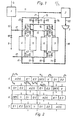
- the method shown in Figure 1 is used to produce organic acids from polysaccharides by biological oxidation with oxygen.
- the required oxygen is generated in an air separation plant 1, preferably a low-temperature rectification plant.
- the fermentation fin. det takes place in a fermenter 2.
- a compressor 3 serves to compress the outflowing from the fermenter Fdbk U hrgases, oxygen and contains as a component to remove carbon dioxide.
- Cyclically switchable adsorbers 4, 5, 6, 7 serve to separate this component, so that the returned oxygen is free of products of the fermentation reaction.
- a gas stream consisting of 84.6% by volume of oxygen, 10.6% by volume of nitrogen and argon and 4.8% by volume of carbon dioxide is passed through line 22 in an amount of 21.1 kmol, / h deducted, compressed in the compressor 3 from 3.5 to 5 bar and fed via a line 16 to the adsorption system.
- This essentially consists of the four cyclically switchable adsorbers 4 to 7, each of which is filled with a bed of wide-pored silica gel, which selectively retains carbon dioxide carried in the recycle gas stream.
- the respective phase-shifted switching cycles of the adsorbers 4 to 7 are shown in the timing diagram in FIG. 2.
- One of the horizontal bars is assigned to each of the four adsorbers. Time goes from left to right.
- the solid line corresponds to the first eighth in which the adsorber 4 is in the first half of the adsorption phase ADS, the adsorber 5 in the first pressure build-up phase D1, the adsorber 6 in the desorption phase DES and the adsorber 7 in the first relaxation phase E1.
- the dashed line corresponds to the second. Eighth, in which the adsorber 4 is in the second half of the adsorption phase ADS, the adsorber 5 in the second pressure build-up phase D2, the adsorber 6 in the displacement phase V and the adsorber 7 in the second relaxation phase E2.
- the oxygen to be cleaned flowing out of the fermenter 2 is accordingly introduced via lines 22 and 16 and an open valve 41 into the adsorber 4, where it is freed of carbon dioxide and via an open valve 45 and Lines 15, 21 and 11 are returned to the fermenter.
- the adsorber 7 is in the first relaxation phase E1, which immediately follows the adsorption phase ADS.
- This adsorber is relieved from its outlet end via an open valve 74, a pressure equalization line 14 and an open valve 54 from the adsorption pressure to an intermediate pressure, the adsorber 5 located in the first pressure build-up phase D1 at the same time via its outlet end to approximately the one mentioned Intermediate pressure is pressed again.
- the composition of the gas mixture flowing out of the adsorber 7 during this pressure equalization process corresponds approximately to the gas mixture flowing in line 16. Since the adsorber during the adsorption ADS are respectively loaded until just before the breakthrough of carbon dioxide and the adsorption front has a certain width, the effluent gas D jerk compensation is, however, somewhat enriched with oxygen compared to the flowing in line 16, the gas mixture. The intermediate pressure reached at the end of the pressure equalization is approx. 3 bar. Meanwhile, the adsorber 6 is in its desorption phase DES. It is fed from its air separation unit 1 via its outlet end and via a line 12, an open valve 17, a line 13 and an open valve 62 at a pressure of approx. 1 bar.
- This residual gas can generally be blown off.
- the total amount of nitrogen supplied to the adsorption system via valve 17 is approximately 8 kmol / h. However, this total amount is not supplied continuously since the desorption phases do not follow one another without gaps. Excess nitrogen is released into the atmosphere via a control valve 18 and a line 9 or stored for other purposes.
- the second relaxation phase E2 of the adsorber 7 begins. Its outlet end is connected via an open valve 72, line 13 and an open valve 62 to the outlet end of the adsorber 6, which thus moves into the displacement phase V occurs.
- the expansion gas at a pressure of approx. 3 bar at the beginning of the second expansion phase which initially has approximately the composition of the gas mixture flowing in line 16 and has an increasing proportion of carbon dioxide towards the end of the second expansion phase, displaces that in the adsorber 6 standing nitrogen through its inlet end, the open valve 63 and the residual gas line 10.
- the displacement phase V is carried out so that the desired degree of displacement is reached as soon as the adsorber 7 has reached a pressure of approximately 1 bar.
- the adsorber 6 Normally, all of the nitrogen will then have escaped from the adsorber 6, the gap volume of which is then essentially filled with oxygen.
- the pressure in the adsorber 6 is then also about 1 bar. This is the lowest pressure in the process.
- the adsorber 6 is thus prepared for the start of pressure build-up. While this is still in the displacement phase V, the adsorber 5 passes through the second pressure build-up phase D2. Its outlet end is connected via the open valve 54, line 14, the open valve 19 and line 20 to the line 21, in which purified oxygen coming from the adsorber 4 flows. A portion of this oxygen is now branched off and, in relation to the direction of flow prevailing during the adsorption phase, passed in countercurrent into the adsorber 5.
- the oxygen fraction branched off via line 20 during the second pressure build-up phase D2 is approximately 10% of that via Ven til 45 outflowing purified oxygen. If the fermenter 2 is to be charged with constant amounts of oxygen, it is advisable to install a buffer tank in the line 11 downstream with respect to the line 21 and to keep the amount of oxygen to be taken from it and fed to the fermenter constant by means of a control valve.
- FIG. 3 shows nine cyclically switchable adsorbers 110 to 190, each of which has identical switching cycles with a time offset. These are connected via valves 111 to 191 to a raw gas line 105, which serves to supply the still unpurified hydrogen-rich gas.
- the inlet sides of the adsorbers 110 to 190 are also connected to a residual gas line 107 via valves 113 to 193.
- the outlet sides of the adsorbers 110 to 190 are first connected via valves 112 to 192 to a product line for the hydrogen-rich gas purified by carbon dioxide and water vapor.
- valves 114 to 194 with a pressure compensation line 102, via valves 116 to 196 with a line 101 serving partly as a pressure compensation, partly as a displacement gas line and partly as a pressure build-up line, which line is connected to the product gas line 106 via a valve 117, and in connection with a purge gas line 103 via valves 115 to 195.
- a hydrogen-rich gas For example, 4500 kmol / h of a hydrogen-rich gas are fed through the raw gas line 105, which consists of approximately 65% by volume of hydrogen, approximately 10% by volume of carbon monoxide and approximately 25% by volume of carbon dioxide and with water vapor is saturated.
- This hydrogen-rich gas is under a pressure of 25 bar and has a temperature of 303K. It comes from a partial oxidation of hydrocarbon-rich materials, such as hydrocarbon oils, with subsequent partial conversion of the carbon monoxide to carbon dioxide.
- the hydrogen-rich gas is to be freed from carbon dioxide and water vapor as much as possible in order to be subsequently subjected to a hydrogen-carbon monoxide separation. Carbon dioxide and water vapor are preferably retained in the adsorbers charged with wide-pore silica gel.
- the purge gas line 103 supplies 1000 kmol / h of gaseous nitrogen of 1.1 bar and 303K, which, like the oxygen required for the partial oxidation, comes from an air separation plant.
- FIG. 4 shows the timing diagram belonging to FIG. 3.
- the nine horizontal bars correspond to the nine adsorbents 110 to 190.
- the cycles which are identical for all adsorbers, can be divided into 36 smallest functional units or cycles.
- An adsorption phase ADS of 12 cycles is followed by a first relaxation phase E 1 of 2 cycles, which is operated in pressure equalization with a third pressure build-up stage D 3 of another adsorber, a second relaxation phase E 2, also in two cycles, which in pressure equalization with one second pressure build-up stage D 2 of another other adsorber is operated, a third expansion stage E 3 of a cycle length, the expansion gas of which, following the desorption phase DES of another adsorber, is passed through this during the following displacement phase V, a fourth expansion phase E 4 of likewise a cycle length , which is operated in pressure equalization with a first pressure build-up stage D 1 of the same other adsorber, a fifth expansion stage E 5 with a cycle length, the expansion gas of which is blown off through
- This purge gas which is a foreign gas with respect to the feed gas to be cleaned, is forced out of the adsorbent bed in the subsequent displacement phase V.
- the adsorber is brought back to the adsorption pressure.
- the adsorption takes place in the adsorber 110 via the opened valves 111 and 112, the first expansion E 1 in cocurrent via the opened valve 114 and the pressure compensation line 102, as well as the second expansion E 2.
- the expansion gas of the third expansion phase E 3 flows through the open valve 116 and line 101, in order to then be passed via a corresponding open valve into another adsorber in order to displace purging gas there.
- the expansion gas of the fourth expansion phase E 4 also flows out via the open valve 116 and the line 1 0 2 in order to carry out a first pressure build-up D 1 in the adsorber previously in the displacement phase V.
- the last expansion gas of the fifth expansion phase E 5 which is now already at a very low pressure and contains desorbed components, is finally drawn off via the opened valve 113 and the residual gas line 107.
- the nitrogen serving as the purge gas enters the adsorber via the purge gas line 103 and the open valve 115 and leaves the adsorber via the open valve 113 and the residual gas line 107.
- the displacement gas flows through the open valves 116 and 113.
- the first pressure build-up D 1 takes place via the open valve 116, the second pressure build-up D 2 via the open valve 114, as does the third pressure build-up D 3.
- the fourth and last pressure build-up D 4 is carried out with purified product gas, specifically via line 101 and the opened valves 117 and 116.
- the last method described is characterized by that the nitrogen obtained anyway in the course of the pretreatment of the feed gas with the aid of the air separation plant can be used in a distributed manner as a purge gas, as a result of which the losses of purified product gas can be reduced to a minimum.
- Purified product gas is only required for the last pressure build-up D 4. The volume required for this is relatively small, since five expansion stages E 1 to E 5 are provided and the pressure difference still present at the beginning of the last pressure build-up D 4 is therefore also correspondingly small.
Landscapes
- Chemical & Material Sciences (AREA)
- Engineering & Computer Science (AREA)
- Analytical Chemistry (AREA)
- General Chemical & Material Sciences (AREA)
- Oil, Petroleum & Natural Gas (AREA)
- Chemical Kinetics & Catalysis (AREA)
- Separation Of Gases By Adsorption (AREA)
- Preparation Of Compounds By Using Micro-Organisms (AREA)
- Oxygen, Ozone, And Oxides In General (AREA)
Applications Claiming Priority (2)
| Application Number | Priority Date | Filing Date | Title |
|---|---|---|---|
| DE2916585 | 1979-04-24 | ||
| DE19792916585 DE2916585A1 (de) | 1979-04-24 | 1979-04-24 | Druckwechsel-adsorptionsverfahren |
Publications (3)
| Publication Number | Publication Date |
|---|---|
| EP0019105A2 true EP0019105A2 (fr) | 1980-11-26 |
| EP0019105A3 EP0019105A3 (en) | 1981-03-25 |
| EP0019105B1 EP0019105B1 (fr) | 1983-06-22 |
Family
ID=6069144
Family Applications (1)
| Application Number | Title | Priority Date | Filing Date |
|---|---|---|---|
| EP80102162A Expired EP0019105B1 (fr) | 1979-04-24 | 1980-04-22 | Procédé d'adsorption en cycle continu et son emploi pour la production d'acides organiques |
Country Status (7)
| Country | Link |
|---|---|
| US (1) | US4371380A (fr) |
| EP (1) | EP0019105B1 (fr) |
| JP (1) | JPS5610320A (fr) |
| BR (1) | BR8002484A (fr) |
| DE (2) | DE2916585A1 (fr) |
| IN (1) | IN152706B (fr) |
| MX (1) | MX155263A (fr) |
Families Citing this family (35)
| Publication number | Priority date | Publication date | Assignee | Title |
|---|---|---|---|---|
| DE3122701A1 (de) * | 1981-06-06 | 1982-12-23 | Bergwerksverband Gmbh, 4300 Essen | Verfahren zur trennung von gasgemischen mittels druckwechseltechnik |
| DE3132758A1 (de) * | 1981-08-19 | 1983-03-03 | Linde Ag, 6200 Wiesbaden | Absorptionsverfahren |
| DE3150137A1 (de) * | 1981-12-18 | 1983-06-30 | Linde Ag, 6200 Wiesbaden | Adsorptionsverfahren zur trennung von kohlenwasserstoffen |
| US4436533A (en) | 1982-12-02 | 1984-03-13 | Shell Oil Company | Adsorption process |
| US4726816A (en) * | 1983-11-08 | 1988-02-23 | Union Carbide Corporation | Reformer-pressure swing adsorption process for the production of carbon monoxide |
| US4512780A (en) * | 1983-11-08 | 1985-04-23 | Union Carbide Corporation | Pressure swing adsorption with intermediate product recovery |
| US4650500A (en) * | 1985-02-22 | 1987-03-17 | Union Carbide Corporation | Enhanced pressure swing adsorption process and system |
| DE3528908A1 (de) * | 1985-08-12 | 1987-02-19 | Linde Ag | Druckwechseladsorptionsverfahren |
| US4690696A (en) * | 1985-10-18 | 1987-09-01 | Air Products And Chemicals, Inc. | Oxidation of carbonaceous material |
| DE3616981A1 (de) * | 1986-05-21 | 1987-11-26 | Linde Ag | Druckwechseladsorptionsverfahren |
| US5051115A (en) * | 1986-05-21 | 1991-09-24 | Linde Aktiengesellschaft | Pressure swing adsorption process |
| US4810265A (en) * | 1987-12-29 | 1989-03-07 | Union Carbide Corporation | Pressure swing adsorption process for gas separation |
| US5090973A (en) * | 1990-10-23 | 1992-02-25 | The Boc Group, Inc. | Psa employing high purity purging |
| US5503658A (en) * | 1993-11-12 | 1996-04-02 | Uop | Process for the removal of volatile organic compounds from a fluid stream |
| US5415682A (en) * | 1993-11-12 | 1995-05-16 | Uop | Process for the removal of volatile organic compounds from a fluid stream |
| US5512082A (en) * | 1993-11-12 | 1996-04-30 | Uop | Process for the removal of volatile organic compounds from a fluid stream |
| US5656065A (en) * | 1995-10-04 | 1997-08-12 | Air Products And Chemicals, Inc. | Multibed pressure swing adsorption apparatus and method for the operation thereof |
| US6063161A (en) * | 1996-04-24 | 2000-05-16 | Sofinoy Societte Financiere D'innovation Inc. | Flow regulated pressure swing adsorption system |
| USRE38493E1 (en) * | 1996-04-24 | 2004-04-13 | Questair Technologies Inc. | Flow regulated pressure swing adsorption system |
| GB9712165D0 (en) * | 1997-06-11 | 1997-08-13 | Air Prod & Chem | Processes and apparatus for producing a gaseous product |
| US5938819A (en) * | 1997-06-25 | 1999-08-17 | Gas Separation Technology Llc | Bulk separation of carbon dioxide from methane using natural clinoptilolite |
| FR2769851B1 (fr) * | 1997-10-21 | 1999-12-17 | Air Liquide | Installation de separation d'un melange de gaz |
| US5997612A (en) * | 1998-07-24 | 1999-12-07 | The Boc Group, Inc. | Pressure swing adsorption process and apparatus |
| US6379431B1 (en) * | 2000-01-20 | 2002-04-30 | Air Products And Chemicals, Inc. | Pressure swing adsorption process with multiple beds on purge and/or with ten beds and four pressure equalization steps |
| US6565628B2 (en) | 2001-07-23 | 2003-05-20 | Air Products And Chemicals, Inc. | Pressure swing adsorption process with reduced pressure equalization time |
| US6699307B1 (en) * | 2002-10-11 | 2004-03-02 | H2Gen Innovations, Inc. | High recovery PSA cycles and apparatus with reduced complexity |
| CN101563138A (zh) * | 2006-12-15 | 2009-10-21 | 陶氏环球技术公司 | 来自发酵液的挥发性产物的回收 |
| JP5492566B2 (ja) * | 2007-11-30 | 2014-05-14 | 東芝三菱電機産業システム株式会社 | 高濃度オゾンガス生成装置および高濃度オゾンガス生成方法 |
| US8029603B2 (en) * | 2009-01-23 | 2011-10-04 | Air Products And Chemicals, Inc. | Pressure swing adsorption cycle for ozone production |
| US8435328B2 (en) | 2011-01-11 | 2013-05-07 | Praxair Technology, Inc. | Ten bed pressure swing adsorption process operating in normal and turndown modes |
| US8551217B2 (en) | 2011-01-11 | 2013-10-08 | Praxair Technology, Inc. | Six bed pressure swing adsorption process operating in normal and turndown modes |
| US8491704B2 (en) | 2011-01-11 | 2013-07-23 | Praxair Technology, Inc. | Six bed pressure swing adsorption process operating in normal and turndown modes |
| US8496733B2 (en) | 2011-01-11 | 2013-07-30 | Praxair Technology, Inc. | Large scale pressure swing adsorption systems having process cycles operating in normal and turndown modes |
| EP3554673B1 (fr) * | 2016-12-13 | 2022-11-09 | Linde GmbH | Procédés de séparation d'ozone |
| US10315152B2 (en) * | 2017-06-08 | 2019-06-11 | DK Engineering Consulting LLC | Method and system for pressure swing adsorption |
Family Cites Families (15)
| Publication number | Priority date | Publication date | Assignee | Title |
|---|---|---|---|---|
| NL297067A (fr) * | 1962-09-04 | 1900-01-01 | ||
| US3430418A (en) * | 1967-08-09 | 1969-03-04 | Union Carbide Corp | Selective adsorption process |
| US3717974A (en) * | 1968-12-30 | 1973-02-27 | Union Carbide Corp | Selective adsorption process for air separation |
| US3564816A (en) * | 1968-12-30 | 1971-02-23 | Union Carbide Corp | Selective adsorption process |
| BE758402A (fr) * | 1969-11-03 | 1971-04-16 | Titan Gmbh | Elimination du sulfure de carbonyle de gaz industriels |
| US3636679A (en) * | 1971-01-04 | 1972-01-25 | Union Carbide Corp | Selective adsorption gas separation process |
| JPS543822B1 (fr) * | 1971-03-27 | 1979-02-27 | ||
| US3738087A (en) * | 1971-07-01 | 1973-06-12 | Union Carbide Corp | Selective adsorption gas separation process |
| DE2337754A1 (de) * | 1972-07-27 | 1974-02-07 | Grace W R & Co | Fraktionierung von gasmischungen |
| US3973931A (en) * | 1974-10-30 | 1976-08-10 | Union Carbide Corporation | Air separation by adsorption |
| AR207266A1 (es) * | 1974-10-30 | 1976-09-22 | Union Carbide Corp | Procedimiento oscilante adiabatico de presion para la separacion de aire |
| DE2460513C3 (de) * | 1974-12-20 | 1979-01-25 | Linde Ag, 6200 Wiesbaden | Verfahren und Vorrichtung zur Zerlegung von Gasgemischen durch adiabatische Ad- und Desorption |
| US3986849A (en) * | 1975-11-07 | 1976-10-19 | Union Carbide Corporation | Selective adsorption process |
| US4140495A (en) * | 1977-05-27 | 1979-02-20 | Union Carbide Corporation | Turndown control for pressure swing adsorption |
| DE2840357A1 (de) * | 1978-09-16 | 1980-04-03 | Linde Ag | Adiabatisches adsorptionsverfahren zur gasreinigung oder-trennung |
-
1979
- 1979-04-24 DE DE19792916585 patent/DE2916585A1/de not_active Withdrawn
-
1980
- 1980-04-22 EP EP80102162A patent/EP0019105B1/fr not_active Expired
- 1980-04-22 DE DE8080102162T patent/DE3063841D1/de not_active Expired
- 1980-04-23 BR BR8002484A patent/BR8002484A/pt unknown
- 1980-04-23 JP JP5301280A patent/JPS5610320A/ja active Granted
- 1980-04-24 MX MX182081A patent/MX155263A/es unknown
- 1980-04-24 US US06/143,241 patent/US4371380A/en not_active Expired - Lifetime
- 1980-08-23 IN IN967/CAL/80A patent/IN152706B/en unknown
Also Published As
| Publication number | Publication date |
|---|---|
| JPS5610320A (en) | 1981-02-02 |
| DE2916585A1 (de) | 1980-11-06 |
| US4371380A (en) | 1983-02-01 |
| IN152706B (fr) | 1984-03-17 |
| JPS6225407B2 (fr) | 1987-06-03 |
| EP0019105A3 (en) | 1981-03-25 |
| BR8002484A (pt) | 1980-12-09 |
| EP0019105B1 (fr) | 1983-06-22 |
| DE3063841D1 (en) | 1983-07-28 |
| MX155263A (es) | 1988-02-12 |
Similar Documents
| Publication | Publication Date | Title |
|---|---|---|
| EP0019105B1 (fr) | Procédé d'adsorption en cycle continu et son emploi pour la production d'acides organiques | |
| EP0146124B1 (fr) | Procédé d'adsorption par pression alternée | |
| DE2443072C2 (de) | Verfahren zur Erzeugung eines mit Sauerstoff angereicherten Gases | |
| DE69803143T2 (de) | Verfahren und Vorrichtung zur Produktion eines gasförmigen Produkts | |
| DE2854060C2 (fr) | ||
| EP0083433B1 (fr) | Procédé d'adsorption pour la séparation d'hydrocarbures | |
| DE3304227C2 (de) | Verfahren und Vorrichtung zur Druckwechseladsorption | |
| EP0291975B1 (fr) | Procédé d'enrichissement d'hélium | |
| EP0157939B1 (fr) | Procédé de production d'oxygène, ayant une faible teneur en argon, à partir d'air | |
| EP0291976B1 (fr) | Procédé de production d'hélium | |
| DE2724763A1 (de) | Verfahren zum reinigen und zerlegen eines gasgemisches | |
| DE2615951A1 (de) | Verfahren zur herstellung von hochreinem stickstoff | |
| EP0103070A2 (fr) | Procédé et dispositif pour la séparation de gaz par des adsorbants | |
| DE2460513A1 (de) | Verfahren und vorrichtung zur zerlegung von gasgemischen durch adiabatische ad- und desorption | |
| DE3132758A1 (de) | Absorptionsverfahren | |
| DE69406613T2 (de) | Verfahren zur Rückgewinnung von Ethylen aus Abgasen der Ethylenoxidherstellung | |
| EP0092695A1 (fr) | Procédé pour la récupération de gaz rares ayant des diamètres atomiques petits, notamment de l'hélium à partir de mixtures de gaz contenant de l'oxygène et/ou de l'azote | |
| DE2624346A1 (de) | Verfahren zur zerlegung von gasen durch adsorption | |
| EP0015413B1 (fr) | Procédé d'adsorption à pression alternée pour la décomposition ou la purification de mélanges de gaz | |
| DE2631890A1 (de) | Verfahren und vorrichtung zur anreicherung einer hauptkomponente eines mindestens zwei hauptkomponenten enthaltenden gasgemisches | |
| EP0146646B1 (fr) | Procédé pour séparer et produire des gaz ayant des propriétés adsorbables relativement élevées, par des adsorbants préparés à partir de mélanges gazeux contenant également des gaz moins adsorbants | |
| DE3207089A1 (de) | Druckwechseladsorptionsverfahren | |
| DE3030081C2 (de) | Verfahren zur adsorptiven Zerlegung eines Gasgemisches | |
| DE4434101C1 (de) | Druckwechsel-Adsorptionsverfahren | |
| DE2337754A1 (de) | Fraktionierung von gasmischungen |
Legal Events
| Date | Code | Title | Description |
|---|---|---|---|
| PUAI | Public reference made under article 153(3) epc to a published international application that has entered the european phase |
Free format text: ORIGINAL CODE: 0009012 |
|
| AK | Designated contracting states |
Designated state(s): BE DE FR GB IT NL |
|
| PUAL | Search report despatched |
Free format text: ORIGINAL CODE: 0009013 |
|
| AK | Designated contracting states |
Designated state(s): BE DE FR GB IT NL |
|
| 17P | Request for examination filed |
Effective date: 19810216 |
|
| ITF | It: translation for a ep patent filed | ||
| GRAA | (expected) grant |
Free format text: ORIGINAL CODE: 0009210 |
|
| AK | Designated contracting states |
Designated state(s): BE DE FR GB IT NL |
|
| REF | Corresponds to: |
Ref document number: 3063841 Country of ref document: DE Date of ref document: 19830728 |
|
| EL | Fr: translation of claims filed | ||
| PLBE | No opposition filed within time limit |
Free format text: ORIGINAL CODE: 0009261 |
|
| STAA | Information on the status of an ep patent application or granted ep patent |
Free format text: STATUS: NO OPPOSITION FILED WITHIN TIME LIMIT |
|
| 26N | No opposition filed | ||
| PGFP | Annual fee paid to national office [announced via postgrant information from national office to epo] |
Ref country code: NL Payment date: 19870430 Year of fee payment: 8 |
|
| PG25 | Lapsed in a contracting state [announced via postgrant information from national office to epo] |
Ref country code: NL Effective date: 19881101 |
|
| NLV4 | Nl: lapsed or anulled due to non-payment of the annual fee | ||
| ITTA | It: last paid annual fee | ||
| PGFP | Annual fee paid to national office [announced via postgrant information from national office to epo] |
Ref country code: DE Payment date: 19930524 Year of fee payment: 14 |
|
| PGFP | Annual fee paid to national office [announced via postgrant information from national office to epo] |
Ref country code: FR Payment date: 19940411 Year of fee payment: 15 |
|
| PGFP | Annual fee paid to national office [announced via postgrant information from national office to epo] |
Ref country code: GB Payment date: 19940412 Year of fee payment: 15 |
|
| PGFP | Annual fee paid to national office [announced via postgrant information from national office to epo] |
Ref country code: BE Payment date: 19940607 Year of fee payment: 15 |
|
| PG25 | Lapsed in a contracting state [announced via postgrant information from national office to epo] |
Ref country code: DE Effective date: 19950103 |
|
| PG25 | Lapsed in a contracting state [announced via postgrant information from national office to epo] |
Ref country code: GB Effective date: 19950422 |
|
| PG25 | Lapsed in a contracting state [announced via postgrant information from national office to epo] |
Ref country code: BE Effective date: 19950430 |
|
| BERE | Be: lapsed |
Owner name: LINDE A.G. Effective date: 19950430 |
|
| GBPC | Gb: european patent ceased through non-payment of renewal fee |
Effective date: 19950422 |
|
| PG25 | Lapsed in a contracting state [announced via postgrant information from national office to epo] |
Ref country code: FR Effective date: 19951229 |
|
| REG | Reference to a national code |
Ref country code: FR Ref legal event code: ST |