EP0019422A2 - Wirbelbettreaktorsystem - Google Patents
Wirbelbettreaktorsystem Download PDFInfo
- Publication number
- EP0019422A2 EP0019422A2 EP80301506A EP80301506A EP0019422A2 EP 0019422 A2 EP0019422 A2 EP 0019422A2 EP 80301506 A EP80301506 A EP 80301506A EP 80301506 A EP80301506 A EP 80301506A EP 0019422 A2 EP0019422 A2 EP 0019422A2
- Authority
- EP
- European Patent Office
- Prior art keywords
- injector
- vessel
- reactor system
- fluidized bed
- bed
- Prior art date
- Legal status (The legal status is an assumption and is not a legal conclusion. Google has not performed a legal analysis and makes no representation as to the accuracy of the status listed.)
- Granted
Links
Images

Classifications
-
- C—CHEMISTRY; METALLURGY
- C01—INORGANIC CHEMISTRY
- C01G—COMPOUNDS CONTAINING METALS NOT COVERED BY SUBCLASSES C01D OR C01F
- C01G31/00—Compounds of vanadium
- C01G31/04—Halides
-
- B—PERFORMING OPERATIONS; TRANSPORTING
- B01—PHYSICAL OR CHEMICAL PROCESSES OR APPARATUS IN GENERAL
- B01J—CHEMICAL OR PHYSICAL PROCESSES, e.g. CATALYSIS OR COLLOID CHEMISTRY; THEIR RELEVANT APPARATUS
- B01J8/00—Chemical or physical processes in general, conducted in the presence of fluids and solid particles; Apparatus for such processes
- B01J8/18—Chemical or physical processes in general, conducted in the presence of fluids and solid particles; Apparatus for such processes with fluidised particles
- B01J8/1818—Feeding of the fluidising gas
Definitions
- This invention relates to reactor systems, and more particularly to a fluidized bed reactor system having an improved means for supplying the fluidizing medium to the reactor system.
- Fluidized bed reactor systems are widely used in the processing and treatment of many materials.
- fluidized bed reactor systems consist of a vessel adapted to contain the fluidized bed with a fluidizing medium fed uniformly into the internal bottom portion of the vessel.
- a constriction plate is positioned within the vessel above the vessel bottom to thereby define a plenum into which fluid, under pressure, is fed. The fluid then flows through nozzles or other suitable openings in the constriction plate at a sufficiently high velocity to fluidize the particular bed located above the constriction plate.
- Another type of fluidized bed reactor system utilizes a plurality of fluid distribution pipes, i.e. injectors, located in the interior bottom portion of the reactor.
- the fluidizing medium under pressure, is then fed through the distribution pipes and out suitably dimensioned holes in the pipes.
- the fluid flows into the vessel at a sufficiently high velocity to fluidize the particular bed.
- a particular problem which develops in fluid bed reactor systems is that the constriction plates and fluid distribution pipes employed by the prior art systems tend to clog and deteriorate.
- the reactor system In order to correct this problem, by either repair or replacement of the constriction plate or distribution pipe, the reactor system must be shut down and cleaned out. Additionally, someone must go into the reactor vessel to disassemble and dismantle the constriction plate or distribution pipe and replace or repair it. This procedure, of necessity, entails a significant amount of shut-down time for the fluid bed reactor systems.
- the invention provides a fluidized bed reactor system which comprises:
- the characteristic feature of the fluidized bed system according to the invention are the shield means (ii) which withdrawal and replacement of the injector to be carried out without shut-down or cleaning of the reactor vessel.
- the fluidized bed reactor system of this invention may be utilized in any process wherein such system would be advantageous.
- a particularly preferred use of the fluidized bed reactor system of this invention is to produce vanadium chlorides by reacting vanadium oxide with chlorine and carbon, see for example, "Process for Producing Vanadium Chlorides" to Cotter et al., U.S. Serial No. 873,297, filed on January 30, 1978, now U.S. Patent 4,169,135, the entire disclosure of which is incorporated herein by reference.
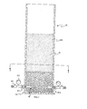
- the fluidizing bed reactor system of this invention is comprised of a vessel (10) adapted to contain a fluidized bed, generally designated (12).
- the vessel (10) is of cylindrical configuration although this invention contemplates that it may be any type configuration, e.g. rectangular, conical, etc.
- the vessel (10) may be made of metal plate, usually a low carbon steel.
- the vessel (10) can be readily fabricated from carbon steel plate by known fabricating techniques. The sections can be readily joined together by welding to complete the vessel.
- the internal surface of the vessel may be lined with an insulation material (not shown) to protect the vessel against the internal high temperatures involved in processing operations.
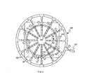
- a plurality of fluid injector means, generally designated (18) are mounted through the vessel wall (20).
- the fluid injector means (18) functions to inject and distribute a fluidizing medium into the lower portion of the bed (12a).
- the fluid injector means (18) preferably replaces the function of the constriction plate utilized in other known fluidized bed reactor systems, but may be utilized to compliment the fluid flow from such constriction plates.
- the upper portion of the bed (12b) contains activated carbon particles and vanadium pentoxide, while the fluidizing medium flowing through the injector means (18) is chlorine gas.
- the lower portion of the bed (12a) may contain a "grog", i.e. a refractory material such as silica, alumina, etc. which is inert and temperature stable.
- the "grog” provides insulation between the high temperature upper portion of the bed (12b), containing, for example, carbon and vanadium pentoxide, and the fluid injector means (18).
- the "grog” may or may not be fluidized.
- the "grog” can act, to a certain extent, as a fluid distribution means.
- each injector means (18) is comprised of an elongated injector (24), preferably projecting radially into the vessel (10) from the vessel wall (20).
- This configuration is particularly preferred when a heating or cooling element (not shown) projects vertically upward in the center of the vessel (10).
- Such element may be supported by plate (16) at the bottom of the vessel (10).
- the injector (24) has a nozzle end (26) projecting into the vessel (10).
- the injector (24) is withdrawably mounted through the vessel wall (20).
- withdrawably mounted or words to that effect, it is meant that the injector (24) is mounted through the vessel wall (20) in such a manner that the injector (24) can be withdrawn from the vessel (10) from outside the vessel (10).
- Fig. 3 depicts a method of withdrawably mounting the injector (24). Preferably this is accomplished by having the injector (24) threadably mounted to the vessel wall (20).
- the injector (24) threadably mounted to the vessel wall (20).
- One skilled in the art can readily conceive of other methods of withdrawably mounting the injector (24) through the vessel wall (20).
- the injector (24) has at least one downwardly directed orifice (28).
- the injector (24) is a tubular member closed at the nozzle end (26) and having a plurality of orifices (28) along the lower half of the member.
- These orifices (28) are of such number and size so as to provide for a sufficiently high velocity and sufficient distribution of fluidizing medium to fluidize the bed (12).
- One skilled in the art can readily determine the number and sizes of such orifices (28).
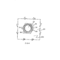
- the shield means is mounted to the vessel wall (20) above the injector (24) extending along the length of the injector (24).
- the shield means (32) maintains a nozzle opening in the bed (12) when the injector (24) is withdrawn.
- the opening is substantially equivalent to the length of the injector (24).
- a problem associated with having a withdrawably mounted injector (24) is that when the injector (24) is withdrawn from the vessel (10), the bed (12), particularly is "grog" is used in the lower portion of the bed (12a), closes or collapses in the area of injector (24) and makes it extremely difficult to reinsert the injector (24) in to the vessel (10).
- the shield means (32) maintains an opening in the bed so that the injector (24) may be reinstated easily into the bed (12).
- the shield means (32) is preferably attached to the vessel wall (20).
- the shield means (32) may be threadably mounted to a coupling (34) attached to the vessel wall (20).
- the shield means (32) reamins in the lower portion of the bed (12a) when the injector (24) is withdrawn from the bed (12).
- the shield means (32) is a pipe member (36) which is concentric to the tubular member used as the injector (24).
- the pipe member (36) is open along the lower half (38) to permit injection of the fluidizing medium from the orifices (28) of the tubular member into the vessel (10).
- a fluid supply means generally designated (48) is in fluid communication with each injector (24) and supplies the fluidizing medium to each nozzle end (26).
- a preferred fluidized bed reactor system has each of the fluid injector means (18) coupled to a gas equalizing header (40). Feeding into the header (40) would be single or multiple gas feed lines (42). Each of the fluid injector means (18), preferably has a pressure gauge (44) and a control valve (46) to control and equalize the flow of fluidizing medium through the fluid injector means (18).
- the control valve (46) is closed and the injector (24) withdrawn from the vessel (10). During this time the fluidized bed system may be kept in operation or shut down, as desired by the operator. A new or repaired injector (24) is then inserted into the vessel (10), attached to the vessel wall (20) and equalizing header (40) and the control valve (46) opened.
- the shield means (32) permits the easy insertion of the injector (24) into the bed (12).
- the shield means (32) is particularly useful if it is desired to shut down the fluid bed (12) or the "grog" is not fluidized, for under these conditions the lower portion of the bed (12a) is dense thereby making it almost impossible to reinsert the injector (24).
Landscapes
- Chemical & Material Sciences (AREA)
- Organic Chemistry (AREA)
- Engineering & Computer Science (AREA)
- Combustion & Propulsion (AREA)
- Chemical Kinetics & Catalysis (AREA)
- Inorganic Chemistry (AREA)
- Devices And Processes Conducted In The Presence Of Fluids And Solid Particles (AREA)
Applications Claiming Priority (2)
| Application Number | Priority Date | Filing Date | Title |
|---|---|---|---|
| US39055 | 1979-05-10 | ||
| US06/039,055 US4241021A (en) | 1979-05-14 | 1979-05-14 | Fluidized bed reactor system |
Publications (3)
| Publication Number | Publication Date |
|---|---|
| EP0019422A2 true EP0019422A2 (de) | 1980-11-26 |
| EP0019422A3 EP0019422A3 (en) | 1981-01-07 |
| EP0019422B1 EP0019422B1 (de) | 1983-04-27 |
Family
ID=21903421
Family Applications (1)
| Application Number | Title | Priority Date | Filing Date |
|---|---|---|---|
| EP80301506A Expired EP0019422B1 (de) | 1979-05-10 | 1980-05-08 | Wirbelbettreaktorsystem |
Country Status (4)
| Country | Link |
|---|---|
| US (1) | US4241021A (de) |
| EP (1) | EP0019422B1 (de) |
| JP (1) | JPS55152540A (de) |
| DE (1) | DE3062877D1 (de) |
Cited By (3)
| Publication number | Priority date | Publication date | Assignee | Title |
|---|---|---|---|---|
| FR2508152A1 (fr) * | 1981-06-19 | 1982-12-24 | Gauzes Michel | Dispositif de sechage de matieres divisees par action d'air chaud sous pression a travers un lit fluidise |
| EP0444614A3 (en) * | 1990-02-27 | 1992-03-04 | Nkk Corporation | Prereduction furnace of a smelting reduction facility of iron ore |
| EP0607601A1 (de) * | 1993-01-20 | 1994-07-27 | Metallgesellschaft Ag | Wirbelschichtreaktor mit Düsenrost |
Families Citing this family (13)
| Publication number | Priority date | Publication date | Assignee | Title |
|---|---|---|---|---|
| JPS5780325A (en) | 1980-09-05 | 1982-05-19 | Nat Res Dev | Coccidial disease vaccine |
| US4436673A (en) | 1980-10-23 | 1984-03-13 | Stauffer Chemical Company | Fluid bed process for preparing phenylphosphonous dichloride |
| US4650566A (en) * | 1984-05-30 | 1987-03-17 | Mobil Oil Corporation | FCC reactor multi-feed nozzle system |
| EP0176123A1 (de) * | 1984-09-28 | 1986-04-02 | Dinamec, naamloze vennootschap | Verfahren zur Entfernung von gasinfizierbaren festen oder flüssigen Materialien von einem hitzebeständigen Träger in einem Wirbelbett und Vorrichtung hierzu |
| ATE45301T1 (de) * | 1985-02-22 | 1989-08-15 | Brian Harding | Gasverteilerrohraufbau fuer wirbelbett. |
| DE3523653A1 (de) * | 1985-07-02 | 1987-02-12 | Bbc Brown Boveri & Cie | Wirbelschichtreaktor |
| US4755138A (en) * | 1986-09-16 | 1988-07-05 | The United States Of America As Represented By The United States Department Of Energy | Fluidized bed calciner apparatus |
| DE4344593C1 (de) * | 1993-12-24 | 1995-02-16 | Somos Gmbh | Vorrichtung zum Trocknen von Schüttgut |
| US6450682B1 (en) | 2000-01-07 | 2002-09-17 | C&M Inc. | Method and apparatus for predicting the end of life of a gas scrubber |
| US6540842B1 (en) | 2000-01-07 | 2003-04-01 | C&M Inc. | Method for in-situ cleaning of a gas scrubber |
| AU2008200662B2 (en) * | 2001-10-11 | 2010-11-18 | Advanced Bioprocess Development Limited | Improvements in and relating to fluid bed expansion and fluidisation |
| GB0124433D0 (en) * | 2001-10-11 | 2001-12-05 | Univ Manchester Metropolitan | Improvemnts in or relating to fluid bed expansion and fluidisation |
| AU2003296876A1 (en) * | 2002-06-21 | 2004-05-04 | Exxonmobil Chemical Patents Inc. | Controlling solids circulation in a gas-solids reaction system |
Family Cites Families (16)
| Publication number | Priority date | Publication date | Assignee | Title |
|---|---|---|---|---|
| US2394651A (en) * | 1943-05-31 | 1946-02-12 | Universal Oil Prod Co | Contact conversion reaction |
| US2494614A (en) * | 1947-11-28 | 1950-01-17 | Universal Oil Prod Co | Process and apparatus for fluidized catalyst regeneration |
| US2647738A (en) * | 1950-12-08 | 1953-08-04 | Shell Dev | Heating powdered material |
| US2798030A (en) * | 1953-03-02 | 1957-07-02 | Phillips Petroleum Co | Method and device for injecting a fluid into a fluidized bed of a particulate material |
| US2910431A (en) * | 1956-07-20 | 1959-10-27 | Exxon Research Engineering Co | Hydroforming and apparatus therefor |
| US2995426A (en) * | 1956-12-04 | 1961-08-08 | Hydrocarbon Research Inc | Elevated fluidizing reactor |
| FR1338537A (fr) * | 1962-08-17 | 1963-09-27 | Siderurgie Fse Inst Rech | Dispositif de fluidisation de matières pulvérulentes |
| US3298793A (en) * | 1963-04-04 | 1967-01-17 | Badger Co | Fluid bed diffusion |
| US3250521A (en) * | 1964-11-06 | 1966-05-10 | Gen Electric | Apparatus for decoating utilizing a heated fluidized bed |
| US3355244A (en) * | 1965-05-14 | 1967-11-28 | Nat Distillers Chem Corp | Production of vanadium oxytrichloride |
| US3721608A (en) * | 1971-07-12 | 1973-03-20 | Fmc Corp | Fluidizing devices for fluid beds,with in-process cleaning |
| US3752224A (en) * | 1971-09-21 | 1973-08-14 | Chicago Bridge & Iron Co | Jacket cooled header air distribution system for fluidized bed reactor |
| US3806324A (en) * | 1971-11-11 | 1974-04-23 | Texaco Inc | Air distribution system for catalyst regenerator |
| US3912460A (en) * | 1973-11-19 | 1975-10-14 | Texaco Development Corp | Method and article for distributing air in a regenerator |
| US4115072A (en) * | 1977-04-07 | 1978-09-19 | Chevron Research Company | Retractable fluids spraying assembly |
| US4169135A (en) * | 1978-01-30 | 1979-09-25 | Stauffer Chemical Company | Process for producing vanadium chlorides |
-
1979
- 1979-05-14 US US06/039,055 patent/US4241021A/en not_active Expired - Lifetime
-
1980
- 1980-04-07 JP JP4555080A patent/JPS55152540A/ja active Pending
- 1980-05-08 EP EP80301506A patent/EP0019422B1/de not_active Expired
- 1980-05-08 DE DE8080301506T patent/DE3062877D1/de not_active Expired
Cited By (6)
| Publication number | Priority date | Publication date | Assignee | Title |
|---|---|---|---|---|
| FR2508152A1 (fr) * | 1981-06-19 | 1982-12-24 | Gauzes Michel | Dispositif de sechage de matieres divisees par action d'air chaud sous pression a travers un lit fluidise |
| EP0444614A3 (en) * | 1990-02-27 | 1992-03-04 | Nkk Corporation | Prereduction furnace of a smelting reduction facility of iron ore |
| US5149062A (en) * | 1990-02-27 | 1992-09-22 | Nkk Corporation | Prereduction furnace of a smelting reduction facility of iron ore |
| EP0607601A1 (de) * | 1993-01-20 | 1994-07-27 | Metallgesellschaft Ag | Wirbelschichtreaktor mit Düsenrost |
| US5401471A (en) * | 1993-01-20 | 1995-03-28 | Metallgesellschaft Aktiengesellschaft | Fluidized bed reactor comprising a nozzle grate |
| AU666996B2 (en) * | 1993-01-20 | 1996-02-29 | Lentjes Gmbh | Fluidized bed reactor comprising a nozzle grate |
Also Published As
| Publication number | Publication date |
|---|---|
| EP0019422A3 (en) | 1981-01-07 |
| EP0019422B1 (de) | 1983-04-27 |
| US4241021A (en) | 1980-12-23 |
| DE3062877D1 (en) | 1983-06-01 |
| JPS55152540A (en) | 1980-11-27 |
Similar Documents
| Publication | Publication Date | Title |
|---|---|---|
| EP0019422B1 (de) | Wirbelbettreaktorsystem | |
| US6994497B1 (en) | Method and apparatus for treating high pressure particulate material | |
| US3861862A (en) | Fuel gun for fluidized bed reactor | |
| CA1247330A (en) | Apparatus in a fluidized bed reactor | |
| EP0459023B1 (de) | Vorrichtung zur Vergasung von kohlenstoffhaltigen Materialien | |
| GB2034446A (en) | Quench ring and dip tube assembly for a reactor vessel | |
| CA1302054C (en) | Fluidizing gas distribution device | |
| US5230868A (en) | Fluidized bed reactor with protected fluid distributor | |
| US4148437A (en) | Combustor | |
| DE102005006570B4 (de) | Verfahren und Vorrichtung zur Fluidisierung einer Wirbelschicht | |
| GB2043476A (en) | Gas distributor for fluidized beds | |
| US4338187A (en) | Solids feeding device and system | |
| US2628158A (en) | Catalyst stripping vessel | |
| CN1079523C (zh) | 流化床锅炉的炉箅装置 | |
| GB1562035A (en) | Fluid bed reactor | |
| EP0008187B1 (de) | Einspritzdüse und damit versehene Verteilerplatte | |
| US4346054A (en) | Fluidizable bed apparatus | |
| US20090218371A1 (en) | Sluice Vessel and Method of Operating Such a Sluice Vessel | |
| US4460130A (en) | High temperature gas distribution injector | |
| US5100629A (en) | Ebullated bed grid plate and skirt to prevent flow maldistribution and catalyst attrition | |
| US4243380A (en) | Method and device for distributing liquid fuel to a fluidized bed | |
| EP0325657A1 (de) | Gaszerstäuberdüse für einen fliessbettofen | |
| DE102017219783A1 (de) | Vorrichtung und Verfahren zum Vergasen von Einsatzstoffen und zum Bereitstellen von Synthesegas sowie Verwendung | |
| US4809886A (en) | Apparatus for controlling a flow of granular material | |
| US2766187A (en) | Method and apparatus for hydrocarbon conversion |
Legal Events
| Date | Code | Title | Description |
|---|---|---|---|
| PUAI | Public reference made under article 153(3) epc to a published international application that has entered the european phase |
Free format text: ORIGINAL CODE: 0009012 |
|
| PUAL | Search report despatched |
Free format text: ORIGINAL CODE: 0009013 |
|
| AK | Designated contracting states |
Designated state(s): DE FR GB IT |
|
| AK | Designated contracting states |
Designated state(s): DE FR GB IT |
|
| 17P | Request for examination filed |
Effective date: 19810611 |
|
| ITF | It: translation for a ep patent filed | ||
| GRAA | (expected) grant |
Free format text: ORIGINAL CODE: 0009210 |
|
| AK | Designated contracting states |
Designated state(s): DE FR GB IT |
|
| REF | Corresponds to: |
Ref document number: 3062877 Country of ref document: DE Date of ref document: 19830601 |
|
| ET | Fr: translation filed | ||
| PGFP | Annual fee paid to national office [announced via postgrant information from national office to epo] |
Ref country code: FR Payment date: 19840302 Year of fee payment: 5 |
|
| PGFP | Annual fee paid to national office [announced via postgrant information from national office to epo] |
Ref country code: DE Payment date: 19840731 Year of fee payment: 5 |
|
| GBPC | Gb: european patent ceased through non-payment of renewal fee | ||
| PG25 | Lapsed in a contracting state [announced via postgrant information from national office to epo] |
Ref country code: FR Free format text: LAPSE BECAUSE OF NON-PAYMENT OF DUE FEES Effective date: 19860131 |
|
| PG25 | Lapsed in a contracting state [announced via postgrant information from national office to epo] |
Ref country code: DE Effective date: 19860201 |
|
| REG | Reference to a national code |
Ref country code: FR Ref legal event code: ST |
|
| PG25 | Lapsed in a contracting state [announced via postgrant information from national office to epo] |
Ref country code: GB Effective date: 19881118 |
|
| PLBE | No opposition filed within time limit |
Free format text: ORIGINAL CODE: 0009261 |
|
| STAA | Information on the status of an ep patent application or granted ep patent |
Free format text: STATUS: NO OPPOSITION FILED WITHIN TIME LIMIT |