EP0019446A1 - Procédé et appareil pour mélanger des substances granulaires - Google Patents
Procédé et appareil pour mélanger des substances granulaires Download PDFInfo
- Publication number
- EP0019446A1 EP0019446A1 EP80301550A EP80301550A EP0019446A1 EP 0019446 A1 EP0019446 A1 EP 0019446A1 EP 80301550 A EP80301550 A EP 80301550A EP 80301550 A EP80301550 A EP 80301550A EP 0019446 A1 EP0019446 A1 EP 0019446A1
- Authority
- EP
- European Patent Office
- Prior art keywords
- blending
- auxiliary
- tube means
- main
- flow characteristics
- Prior art date
- Legal status (The legal status is an assumption and is not a legal conclusion. Google has not performed a legal analysis and makes no representation as to the accuracy of the status listed.)
- Granted
Links
- 238000002156 mixing Methods 0.000 title claims abstract description 94
- 238000000034 method Methods 0.000 title claims description 7
- 239000008187 granular material Substances 0.000 title abstract description 10
- 239000000463 material Substances 0.000 claims abstract description 59
- 239000007787 solid Substances 0.000 claims abstract description 9
- 230000005484 gravity Effects 0.000 claims abstract description 8
- 239000011236 particulate material Substances 0.000 claims description 7
- 239000000203 mixture Substances 0.000 claims description 3
- 238000000518 rheometry Methods 0.000 abstract 1
- 238000010926 purge Methods 0.000 description 10
- 239000007789 gas Substances 0.000 description 7
- 230000000694 effects Effects 0.000 description 5
- 229920005989 resin Polymers 0.000 description 4
- 239000011347 resin Substances 0.000 description 4
- 239000004698 Polyethylene Substances 0.000 description 3
- -1 polyethylene Polymers 0.000 description 3
- 229920000573 polyethylene Polymers 0.000 description 3
- 229910000755 6061-T6 aluminium alloy Inorganic materials 0.000 description 2
- 229910000838 Al alloy Inorganic materials 0.000 description 2
- 229910045601 alloy Inorganic materials 0.000 description 2
- 239000000956 alloy Substances 0.000 description 2
- 230000000712 assembly Effects 0.000 description 2
- 238000000429 assembly Methods 0.000 description 2
- 229920001903 high density polyethylene Polymers 0.000 description 2
- 239000004700 high-density polyethylene Substances 0.000 description 2
- 230000001105 regulatory effect Effects 0.000 description 2
- 230000003247 decreasing effect Effects 0.000 description 1
- 238000007599 discharging Methods 0.000 description 1
- 239000000428 dust Substances 0.000 description 1
- 230000001747 exhibiting effect Effects 0.000 description 1
- 229920001684 low density polyethylene Polymers 0.000 description 1
- 239000004702 low-density polyethylene Substances 0.000 description 1
- 239000008188 pellet Substances 0.000 description 1
- 229920013716 polyethylene resin Polymers 0.000 description 1
- 239000011343 solid material Substances 0.000 description 1
- 239000000725 suspension Substances 0.000 description 1
- 229920005992 thermoplastic resin Polymers 0.000 description 1
- 238000011144 upstream manufacturing Methods 0.000 description 1
Images

Classifications
-
- B—PERFORMING OPERATIONS; TRANSPORTING
- B01—PHYSICAL OR CHEMICAL PROCESSES OR APPARATUS IN GENERAL
- B01F—MIXING, e.g. DISSOLVING, EMULSIFYING OR DISPERSING
- B01F25/00—Flow mixers; Mixers for falling materials, e.g. solid particles
- B01F25/80—Falling particle mixers, e.g. with repeated agitation along a vertical axis
- B01F25/82—Falling particle mixers, e.g. with repeated agitation along a vertical axis uniting flows of material taken from different parts of a receptacle or from a set of different receptacles
- B01F25/821—Falling particle mixers, e.g. with repeated agitation along a vertical axis uniting flows of material taken from different parts of a receptacle or from a set of different receptacles by means of conduits having inlet openings at different levels
Definitions
- the present invention relates to a method and apparatus for blending freely-flowing granular materials contained within a hoppered bin. Operation may be in either a continuous mode with the simultaneous loading and discharge of material (with a predetermined material volume maintained in the bin) or in a batch mode with consecutive loading and discharge.
- the blending operation is accomplished by withdrawing material by gravity flow from a multitude of locations distributed essentially uniformly within the designated blending region of the bin.
- the blending region may be the whole or merely part of the total bin volume depending on the application.
- a method for the high efficiency blending of solid particulate materials which comprises: introducing the materials to be mixed into a bin; withdrawing one portion of said solid particulate materials by gravity through downwardly-extending main blending tube means having positioned through the walls thereof, a plurality of material inlet passages positioned and dimensioned to provide unblocked or starved flow characteristics therethrough; withdrawing another portion of said solid particulate materials by gravity through a plurality of downwardly extending auxiliary blend tube means having positioned.
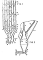
- the apparatus comprises a hoppered bin 10 having a main blending tube 12 and a plurality of auxiliary blending tubes 14 which join into an enlarged section 16 below the main tube 12. Holes or passages '18a and 18b respectively pass through the tube walls of the main and auxiliary blending tubes 12 and 14.
- the blending tubes are positioned to allow the granular material to flow into the tube interiors wherein it flows downward toward the discharge outlet at the lower section of the hoppered bin or blender 10.
- the material outlet flow rate is controlled by setting of valve means positioned at the downstream end of the blender.
- the passages or holes 18a of the main tube are typically distributed uniformly over its length and are sized so that, for the minimum discharge rate and the fastest flowing granular material to be blended, these holes can provide only, for example, 75 percent of the discharge rate. That is, the main blending tube 12 should always be “starved” or unblocked.
- the additional material required for the minimum and higher discharge rates is provided by the combination of "hopper flow" of material through the annular space 20 around the blending skirt 22 and flow of material through passages or holes 18b of and through the auxiliary blending tubes 14.
- Open or closed blender embodiments may be alternatively employed within the scope of the present invention depending upon the use to which the blender is to be put. Continuous operation would favor an open blender (open at the top to the atmosphere and enabling continuous filling), but closed continuous operation blenders, as described hereinbelow, may also be employed. It has been found that the closed embodiment is the most preferred embodiment for all operations of the blender, of the present invention. Such a closed top blender provides shelter from the admission of foreign matter into the hopper blender bin as well as a means for providing additional structural support for the internal blending tube assembly
- the flow rate of material into the enlarged section 16 of the main tube 12 from the auxiliary tube 14 is self-regulated so that, for a larger than minimum discharge rate, the additional material required is automatically provided. : .
- auxiliary blending tubes provide for the self-regulation of material flow rates at auxiliary tubes.
- this self-regulation effect is needed.
- the enlarged section inner cross-sectional area at the discharge section of the tubes should be substantially equal to or larger than the combined auxiliary blending areas at the points of junction with the enlarged section.
- the self-regulation effect, described above, is provided by satisfying the unity or greater ratio between the enlarged section cross-sectional area and the combined auxiliary blending junction tube areas at the points of junction with the enlarged section.
- the discharge rate is less than the maximum combined flow rates of the hopper and the main and auxiliary blending tubes, then a densely-packed but flowing region will build up in the enlarged section until the auxiliary tube openings are almost completely blocked.
- each auxiliary tube provides a generally equal contribution to the total material passed through all the auxiliary tubes.
- auxiliary blending tubes 14 are required to feed material over a wide range of flow rates, these tubes do not operate in a "starved" manner. If a blending tube is discharging material at a lower rate than is possible with the given number of material inlet metering passages or holes, then a region of densely-packed but flowing material will build up in the tube so that the appropriate number of lower holes are closed by the presence of the densely-packed region and, therefore, are not feeding. Holes located above the upper level of densely-packed material can feed freely.
- each auxiliary blending tube 14 has a multitude of passages or holes which are distributed over only a part of the vertical expanse of the blending region.
- the combination of upper feeding holes of all the auxiliary tubes are intended to be essentially uniformly distributed over the blending region regardless of the total discharge rate.
- metering holes have been shown at only specific portions of the auxiliary tubes of the embodiment of blender shown in Fig. 1 of the drawings. It is to be understood that for both continuous and batch operation modes such holes may extend up to substantially the entire length of such - auxiliary tubes.
- a multiplicity of auxiliary tubes (three or more)is used in the embodiment of the drawings so that the upper flow from all of the auxiliary tubes combined will approximate the desired uniform withdrawal from the blending region.
- a relatively small number of tubes are needed to match the performance of previously known gravity blending systems with many more blending tubes. This naturally effects a considerable cost reduction.
- the bottom of the main blending tube 12 consists of a conical section (blending tube flare) 22, the bottom of which partially spans the cylindrical section 24 of the outlet hopper.
- This hopper is designed to provide a "mass flow" with approximately constant material flow velocity across its cross-section. Flow into the outlet hopper 24 will come from both the combined blending tubes and the annular gap 20 between the blending tube flare and the inner hopper walls. The ratio of the two flow rates has been found to be approximately equal to the ratio of the annual gap area to that of the blending tube flare.
- the material level in the blender will be decreasing.
- Material metering holes or passages located above the material level become inoperative and it is necessary to provide additional feeding holes which become active only when the material level is lowered.
- These holes are distributed on the auxiliary blending tubes in such a way that, regardless of the level, material is withdrawn in an approximately uniform manner from the region of the bin containing material.
- a constant, predetermined volume of material is in the blender and the additional holes are prevented from feeding by the densely-packed material in the auxiliary blending tubes.
- the blender described herein can also be employed with a purging operation as shown in Fig. 2 of the drawing. Such an operation is required if flammable gases tend to evolve from the granular material (e.g., low.density polyethylene pellets). By maintaining an air flow through the blender, these gases can be expelled, preventing a combustible mixture from accumulating in the hopper bin.
- a purging operation as shown in Fig. 2 of the drawing.
- the purging gas such as air
- the purging gas is - introduced through inlet conduit 26 and, in turn, the purge inlet line 28 to the purge gas distributor 30 positioned within the hopper bin 10.
- An additional purge gas line 32 is positioned in the material outlet line 34 immediately upstream of the material outlet sliding gate valve 36.
- a purge gas valve 38 is positioned in the additional purge gas line 32 and is preferentially maintained open for initial filling only while material outlet valve 36 is closed.
- Fig. 3 of the drawings The entire blending apparatus of the invention is shown schematically in Fig. 3 of the drawings.
- the embodiment there shown is a closed blender having a top cover 40 and tube access port closures 42 positioned therein.
- a dust collector outlet port member 44 is also secured to the top closure 40 as is the entry of resin inlet through resin inlet tube 46.
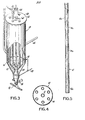
- the main blending tube 12 and the six auxiliary blending tubes 14 are also shown as positioned in the interior of the blender body 10. All blending tubes terminate in the enlarged section 22 at the base of the blender.
- Purge air entering through inlet line 48 passes to both the purge air distributor 50 within the blender body 10 and the lower section of the outlet of the blender.
- Also positioned as shown in Fig. 3 are the outlet slide valve 36 and outlet blender resin line 52.
- auxiliary blending tubes 14 are positioned around the main blending tube 12 within blender body 10.
- Fig. 5 of the drawings shows the main blending tube 12 and the orientation of the main blending tube holes 18a, successively positioned at 90° from each other along the length of the main blending tube.
- An exploded view showing of the six auxiliary blending tubes 14 appears in Fig. 6 of the drawings, together with a preferred relative positioning arrangement for the auxiliary blending tube holes 18b.
- the blender of the embodiment of the figures of the drawings is such that the preferred manner of suspension of the main and auxiliary blending tubes is shown as a triple level assembly of supporting members designated as 54a, 54b and 54c in Figs. 1 and 7.
- levels 1, 2 and 3 show these assemblies within the outer blender wall 10:
- Level 1 and level 3 are substantially identical, with level 2 providing the alter- . nate.of pair support for levels 1 and 3.
- Each level support assembly encloses the main blending tube 12 and the auxiliary blending tubes 14 by respective supporting enclosure within outer sleeve members 60 and 62, respectively.
- These outer sleeve members are, in turn, connected through support members 64 to either of the sleeve members or the blender walls as shown in the three levels of Fig. 7.
- the method and apparatus of the invention can be employed to effect the blending of any solid granular materials. They are particularly well suited to the blending of materials of thermoplastic resin (such as low density polyethylene, high density polyethylene and the like). Blenders of this type exhibit high blending efficiency and high throughput capacity (i.e. greater than 40,000 pounds per hour) in the handling of polyethylene granular materials.
- thermoplastic resin such as low density polyethylene, high density polyethylene and the like.
- Blenders of this type exhibit high blending efficiency and high throughput capacity (i.e. greater than 40,000 pounds per hour) in the handling of polyethylene granular materials.
- blending apparatus was constructed capable of providing adjustable material transfer rates (throughput capacity) of between 15,000 and 40,000 pounds/hour of granular polyethylene material.
- This blending apparatus was of the general design as shown in the embodiment of the figures of the drawings. This blender is capable of handling a wide variety of granular materials, such as both low and high density granular polyethylene resins.
- the total volume of the blender was 13,000 cubic feet which provided a 7,000 cubic foot blending volume (the predetermined minimum material volume maintained during continuous mode blending).
- the outer bin shell of the blender was constructed of 5052-H32 aluminum alloy of 16 feet inside diameter and approximately 60 feet in height of the cylindrical section with a bottom hopper angle of 60° from the horizontal.
- the outlet hopper insert below the main hopper was constructed of similar aluminum alloy, had a 39 inch inside diameter, 30 inch height of the cylindrical section and a hopper angle of 70° from the horizontal.
- the outlet of the hopper was 12 inches in inside diameter.
- the main blending tube comprised 8-inch 6061-T6 aluminum alloy pipe of length sufficient to extend to the top of the bin.
- Thirty-four main blending tube holes each having a diameter of 1-3/8 inches and distributed uniformly over the blending region, were provided. The holes were drilled perpendicular to the tube center line and deburred. Two holes were positioned in each elevation spaced 180° apart. The hole pairs were positioned with a 90° rotation from those of the preceding elevation position.
- the auxiliary blending tubes were six in number, each composed of 6061-T6 aluminum alloy pipes having a 6-inch diameter and of length sufficient to extend to the top of the bin.
- Each of the auxiliary blending tubes had a group of from 16 to 48 holes of 1-3/8 inch diameter which were relatively positioned in a hole pattern similar to that employed in the main blending tube.
- the purge air flow rate of 250 SCFM is provided to be maintained at all tines.
- the minimum discharge rate for the operation of the blender employing high density polyethylene material is 15,000 pounds per hour, with a calculated 10,540 pounds per hour flowing through the main tube, 2435 pounds per hour flowing through the combined auxiliary tubes and 2025 pounds per hour flowing through the annular gap 20 between the blending tube flare and the hopper bin walls.
- the maximum discharge rate is 40,000 pounds per hour with a calculated 10,540 pounds per hour passing through the main tube, 24,060 pounds per hour through the combined auxiliary tubes and 5400 pounds per hour passing through the annular gap.
- the annular gap flow is always a fixed percentage of the total output, but the main blending tube flows a constant rate of material and the aggregate auxiliary blending tubes flow a self-regulated output to provide the additional material required.
Landscapes
- Chemical & Material Sciences (AREA)
- Chemical Kinetics & Catalysis (AREA)
- Processing And Handling Of Plastics And Other Materials For Molding In General (AREA)
- Preparation Of Clay, And Manufacture Of Mixtures Containing Clay Or Cement (AREA)
- Processing Of Solid Wastes (AREA)
- Mixers Of The Rotary Stirring Type (AREA)
Priority Applications (1)
| Application Number | Priority Date | Filing Date | Title |
|---|---|---|---|
| AT80301550T ATE3370T1 (de) | 1979-05-14 | 1980-05-12 | Verfahren und apparat zum mischen koerniger stoffe. |
Applications Claiming Priority (4)
| Application Number | Priority Date | Filing Date | Title |
|---|---|---|---|
| US3873879A | 1979-05-14 | 1979-05-14 | |
| US38738 | 1979-05-14 | ||
| US06/082,471 US4285602A (en) | 1979-05-14 | 1979-10-09 | Method and apparatus for the blending of granular materials |
| US82471 | 1993-06-28 |
Publications (2)
| Publication Number | Publication Date |
|---|---|
| EP0019446A1 true EP0019446A1 (fr) | 1980-11-26 |
| EP0019446B1 EP0019446B1 (fr) | 1983-05-18 |
Family
ID=26715495
Family Applications (1)
| Application Number | Title | Priority Date | Filing Date |
|---|---|---|---|
| EP80301550A Expired EP0019446B1 (fr) | 1979-05-14 | 1980-05-12 | Procédé et appareil pour mélanger des substances granulaires |
Country Status (17)
| Country | Link |
|---|---|
| US (1) | US4285602A (fr) |
| EP (1) | EP0019446B1 (fr) |
| AR (1) | AR223872A1 (fr) |
| AU (1) | AU535020B2 (fr) |
| BR (1) | BR8002923A (fr) |
| CA (1) | CA1134810A (fr) |
| DE (1) | DE3063275D1 (fr) |
| DK (1) | DK209580A (fr) |
| ES (1) | ES491425A0 (fr) |
| FI (1) | FI74407C (fr) |
| GR (1) | GR68466B (fr) |
| MX (1) | MX150186A (fr) |
| NO (1) | NO153391C (fr) |
| NZ (1) | NZ193701A (fr) |
| PH (1) | PH16817A (fr) |
| PT (1) | PT71230A (fr) |
| SG (1) | SG39084G (fr) |
Cited By (5)
| Publication number | Priority date | Publication date | Assignee | Title |
|---|---|---|---|---|
| EP0094803A3 (fr) * | 1982-05-14 | 1985-06-19 | Technovators, Inc | Système de mélange de matières |
| US4818117A (en) * | 1986-03-07 | 1989-04-04 | Avt Anlagen-Und Verfahrenstechnik Gmbh | Apparatus for mixing bulk materials in dust, powder or coarse grained form |
| EP0565755A1 (fr) * | 1992-04-15 | 1993-10-20 | Silo Verfahrens AG | Dispositif pour mélanger des particules en vrac dans un récipient |
| AT400368B (de) * | 1991-12-09 | 1995-12-27 | Huemer E Unistrap Verpackung | Dosierverfahren und vorrichtung zu dessen durchführung |
| NL2010607A (nl) * | 2012-04-12 | 2013-10-16 | Coperion Gmbh | Menginrichting evenals mengsysteem met een dergelijke menginrichting. |
Families Citing this family (19)
| Publication number | Priority date | Publication date | Assignee | Title |
|---|---|---|---|---|
| US4472064A (en) * | 1982-03-19 | 1984-09-18 | Phillips Petroleum Company | Method and apparatus for blending solids or the like |
| US4560285A (en) * | 1982-05-14 | 1985-12-24 | Technovators, Inc. | Material blending system |
| US4473300A (en) * | 1983-08-29 | 1984-09-25 | Phillips Petroleum Company | Method and apparatus for blending solids or the like |
| US4573800A (en) * | 1984-12-10 | 1986-03-04 | Fuller Company | Blender bulk feed valve |
| US4629328A (en) * | 1985-08-29 | 1986-12-16 | Allied Industries, Inc. | Gravity blending apparatus and methods of gravity blending |
| DE3620749A1 (de) * | 1986-06-20 | 1987-12-23 | Waeschle Maschf Gmbh | Umwaelzmischer fuer schuettgut |
| US5009508A (en) * | 1990-03-26 | 1991-04-23 | Wojdylo Henry K | Apparatus for mixing concrete |
| US5123749A (en) * | 1991-04-10 | 1992-06-23 | Avery Jr Hugh E | Blender for particulate materials |
| US5938326A (en) * | 1997-07-24 | 1999-08-17 | Asphalt Technology & Consulting, Inc. | Combination dispersion and skimming device |
| US6403748B1 (en) * | 2000-04-26 | 2002-06-11 | Union Carbide Chemicals & Plastics Technology Corporation | Enhancing production of resin withing specifications |
| US8162531B2 (en) * | 2005-06-22 | 2012-04-24 | Siemens Industry, Inc. | Mixing system for increased height tanks |
| US20080237044A1 (en) * | 2007-03-28 | 2008-10-02 | The Charles Stark Draper Laboratory, Inc. | Method and apparatus for concentrating molecules |
| WO2008130618A1 (fr) * | 2007-04-19 | 2008-10-30 | The Charles Stark Draper Laboratory, Inc. | Procédé et appareil pour séparer des particules, cellules, molécules et matières particulaires |
| US7837379B2 (en) * | 2007-08-13 | 2010-11-23 | The Charles Stark Draper Laboratory, Inc. | Devices for producing a continuously flowing concentration gradient in laminar flow |
| JP2011121048A (ja) * | 2009-12-09 | 2011-06-23 | Rohm & Haas Co | 固体触媒物質をブレンドし、管状構造物に装填する方法 |
| US9028132B2 (en) * | 2011-03-11 | 2015-05-12 | Bayer Materialscience Ag | Mixing silo |
| CN106573798B (zh) * | 2014-06-20 | 2020-04-17 | 海德罗诺威什公司 | 水处理系统储罐及组装方法 |
| US9475016B2 (en) * | 2014-11-28 | 2016-10-25 | Htc Corporation | Fluid mixing structure |
| USD882186S1 (en) * | 2018-12-18 | 2020-04-21 | Zaxe Technologies Inc. | Automatic animal feeder |
Citations (6)
| Publication number | Priority date | Publication date | Assignee | Title |
|---|---|---|---|---|
| SU175887A (fr) * | ||||
| US3233796A (en) * | 1963-04-30 | 1966-02-08 | Reimbert Andre | Device for thoroughly emptying boot silos |
| US3268215A (en) * | 1964-07-31 | 1966-08-23 | Acheson Ind Inc | Blending apparatus |
| GB1099033A (en) * | 1964-01-24 | 1968-01-10 | Phillips Petroleum Co | Apparatus for the blending of flowable particulate solids |
| US3936037A (en) * | 1974-05-22 | 1976-02-03 | Allied Industries, Inc. | Vented gravity blender |
| US4068828A (en) * | 1976-11-19 | 1978-01-17 | Phillips Petroleum Company | Blending of particulate materials |
Family Cites Families (4)
| Publication number | Priority date | Publication date | Assignee | Title |
|---|---|---|---|---|
| US3158362A (en) * | 1962-06-07 | 1964-11-24 | Acheson Ind Inc | Method of blending granular materials |
| US3138369A (en) * | 1962-12-07 | 1964-06-23 | Phillips Petroleum Co | Blending apparatus |
| US3275303A (en) * | 1964-10-05 | 1966-09-27 | Phillips Petroleum Co | Blending |
| US3351326A (en) * | 1964-10-07 | 1967-11-07 | Rexall Drug Chemical | Process and apparatus for solids blending |
-
1979
- 1979-10-09 US US06/082,471 patent/US4285602A/en not_active Expired - Lifetime
-
1980
- 1980-05-06 CA CA000351344A patent/CA1134810A/fr not_active Expired
- 1980-05-12 NO NO801405A patent/NO153391C/no unknown
- 1980-05-12 EP EP80301550A patent/EP0019446B1/fr not_active Expired
- 1980-05-12 BR BR8002923A patent/BR8002923A/pt not_active IP Right Cessation
- 1980-05-12 FI FI801529A patent/FI74407C/fi not_active IP Right Cessation
- 1980-05-12 DE DE8080301550T patent/DE3063275D1/de not_active Expired
- 1980-05-13 PT PT71230A patent/PT71230A/pt unknown
- 1980-05-13 GR GR61933A patent/GR68466B/el unknown
- 1980-05-13 AR AR280998A patent/AR223872A1/es active
- 1980-05-13 AU AU58352/80A patent/AU535020B2/en not_active Ceased
- 1980-05-13 ES ES491425A patent/ES491425A0/es active Granted
- 1980-05-13 MX MX182299A patent/MX150186A/es unknown
- 1980-05-13 DK DK209580A patent/DK209580A/da not_active Application Discontinuation
- 1980-05-13 PH PH24011A patent/PH16817A/en unknown
- 1980-05-13 NZ NZ193701A patent/NZ193701A/en unknown
-
1984
- 1984-05-23 SG SG390/84A patent/SG39084G/en unknown
Patent Citations (7)
| Publication number | Priority date | Publication date | Assignee | Title |
|---|---|---|---|---|
| SU175887A (fr) * | ||||
| US3233796A (en) * | 1963-04-30 | 1966-02-08 | Reimbert Andre | Device for thoroughly emptying boot silos |
| GB1099033A (en) * | 1964-01-24 | 1968-01-10 | Phillips Petroleum Co | Apparatus for the blending of flowable particulate solids |
| US3268215A (en) * | 1964-07-31 | 1966-08-23 | Acheson Ind Inc | Blending apparatus |
| GB1080092A (en) * | 1964-07-31 | 1967-08-23 | Acheson Ind Inc | Improvements in or relating to the blending of granular or particulate material |
| US3936037A (en) * | 1974-05-22 | 1976-02-03 | Allied Industries, Inc. | Vented gravity blender |
| US4068828A (en) * | 1976-11-19 | 1978-01-17 | Phillips Petroleum Company | Blending of particulate materials |
Cited By (6)
| Publication number | Priority date | Publication date | Assignee | Title |
|---|---|---|---|---|
| EP0094803A3 (fr) * | 1982-05-14 | 1985-06-19 | Technovators, Inc | Système de mélange de matières |
| US4818117A (en) * | 1986-03-07 | 1989-04-04 | Avt Anlagen-Und Verfahrenstechnik Gmbh | Apparatus for mixing bulk materials in dust, powder or coarse grained form |
| AT400368B (de) * | 1991-12-09 | 1995-12-27 | Huemer E Unistrap Verpackung | Dosierverfahren und vorrichtung zu dessen durchführung |
| EP0565755A1 (fr) * | 1992-04-15 | 1993-10-20 | Silo Verfahrens AG | Dispositif pour mélanger des particules en vrac dans un récipient |
| NL2010607A (nl) * | 2012-04-12 | 2013-10-16 | Coperion Gmbh | Menginrichting evenals mengsysteem met een dergelijke menginrichting. |
| BE1021672B1 (de) * | 2012-04-12 | 2016-01-05 | Coperion Gmbh | Mischeinrichtung sowie mischsystem mit einer derartigen mischeinrichtung |
Also Published As
| Publication number | Publication date |
|---|---|
| AR223872A1 (es) | 1981-09-30 |
| FI74407C (fi) | 1988-02-08 |
| NO153391B (no) | 1985-12-02 |
| DE3063275D1 (en) | 1983-07-07 |
| EP0019446B1 (fr) | 1983-05-18 |
| AU535020B2 (en) | 1984-03-01 |
| ES8102834A1 (es) | 1981-02-16 |
| NO153391C (no) | 1986-03-12 |
| MX150186A (es) | 1984-03-29 |
| FI801529A7 (fi) | 1980-11-15 |
| PT71230A (en) | 1980-06-01 |
| NZ193701A (en) | 1984-07-31 |
| GR68466B (fr) | 1982-01-04 |
| US4285602A (en) | 1981-08-25 |
| AU5835280A (en) | 1980-11-20 |
| ES491425A0 (es) | 1981-02-16 |
| DK209580A (da) | 1980-11-15 |
| BR8002923A (pt) | 1980-12-23 |
| NO801405L (no) | 1980-11-17 |
| SG39084G (en) | 1985-02-08 |
| PH16817A (en) | 1984-03-06 |
| CA1134810A (fr) | 1982-11-02 |
| FI74407B (fi) | 1987-10-30 |
Similar Documents
| Publication | Publication Date | Title |
|---|---|---|
| US4285602A (en) | Method and apparatus for the blending of granular materials | |
| US4478517A (en) | Process and gravity feed mixer for mixing bulk materials in a container | |
| US3807705A (en) | Process and apparatus for solids blending | |
| US3258252A (en) | Apparatus for blending free-flowing granular materials | |
| US4818117A (en) | Apparatus for mixing bulk materials in dust, powder or coarse grained form | |
| US4128343A (en) | Apparatus for blending granular materials | |
| US4042220A (en) | Apparatus for solids blending | |
| EP0381424B1 (fr) | Dispositif pour mélanger et décharger de la matière solide particulaire d'un récipient | |
| US4486101A (en) | Apparatus for blending particulate materials | |
| US3145975A (en) | Blending apparatus | |
| JPS6234412B2 (fr) | ||
| US4978228A (en) | Mixing bin | |
| US5123749A (en) | Blender for particulate materials | |
| US5074670A (en) | Blender with feed rate control | |
| KR830001022B1 (ko) | 입자 물질들의 혼합을 위한 방법 | |
| JPH0239302B2 (fr) | ||
| CS252453B2 (cs) | Způsob směšování pevných částícových materiálů a zařízení k provádění tohoto způsobu | |
| GB1586895A (en) | Apparatus and method for mixing loose particulate material | |
| JP4738780B2 (ja) | 粉粒体の流動循環装置 | |
| SU1761243A1 (ru) | Пневматический смеситель сыпучих материалов | |
| CN1248955A (zh) | 用于提供层状气流以流化或输送散装固体的组件 | |
| JPS61273424A (ja) | 分配方法 | |
| SU1194472A1 (ru) | Пневматический смеситель | |
| JPS61263522A (ja) | 粉体の分配方法 | |
| EP0538445B1 (fr) | Melangeur realisant une chicane instantanee de matiere particulaire |
Legal Events
| Date | Code | Title | Description |
|---|---|---|---|
| PUAI | Public reference made under article 153(3) epc to a published international application that has entered the european phase |
Free format text: ORIGINAL CODE: 0009012 |
|
| AK | Designated contracting states |
Designated state(s): AT BE CH DE FR GB IT LU NL SE |
|
| 17P | Request for examination filed |
Effective date: 19810209 |
|
| RAP1 | Party data changed (applicant data changed or rights of an application transferred) |
Owner name: UNION CARBIDE CORPORATION |
|
| ITF | It: translation for a ep patent filed | ||
| GRAA | (expected) grant |
Free format text: ORIGINAL CODE: 0009210 |
|
| AK | Designated contracting states |
Designated state(s): AT BE CH DE FR GB IT LI NL SE |
|
| REF | Corresponds to: |
Ref document number: 3370 Country of ref document: AT Date of ref document: 19830615 Kind code of ref document: T |
|
| ET | Fr: translation filed | ||
| REF | Corresponds to: |
Ref document number: 3063275 Country of ref document: DE Date of ref document: 19830707 |
|
| PGFP | Annual fee paid to national office [announced via postgrant information from national office to epo] |
Ref country code: DE Payment date: 19840313 Year of fee payment: 5 |
|
| PGFP | Annual fee paid to national office [announced via postgrant information from national office to epo] |
Ref country code: FR Payment date: 19840316 Year of fee payment: 5 |
|
| PLBE | No opposition filed within time limit |
Free format text: ORIGINAL CODE: 0009261 |
|
| STAA | Information on the status of an ep patent application or granted ep patent |
Free format text: STATUS: NO OPPOSITION FILED WITHIN TIME LIMIT |
|
| PGFP | Annual fee paid to national office [announced via postgrant information from national office to epo] |
Ref country code: SE Payment date: 19840331 Year of fee payment: 5 |
|
| 26N | No opposition filed | ||
| PGFP | Annual fee paid to national office [announced via postgrant information from national office to epo] |
Ref country code: CH Payment date: 19840605 Year of fee payment: 5 |
|
| PGFP | Annual fee paid to national office [announced via postgrant information from national office to epo] |
Ref country code: BE Payment date: 19840630 Year of fee payment: 5 |
|
| PGFP | Annual fee paid to national office [announced via postgrant information from national office to epo] |
Ref country code: AT Payment date: 19860327 Year of fee payment: 7 |
|
| PGFP | Annual fee paid to national office [announced via postgrant information from national office to epo] |
Ref country code: NL Payment date: 19870531 Year of fee payment: 8 |
|
| PG25 | Lapsed in a contracting state [announced via postgrant information from national office to epo] |
Ref country code: GB Effective date: 19880512 Ref country code: AT Effective date: 19880512 |
|
| PG25 | Lapsed in a contracting state [announced via postgrant information from national office to epo] |
Ref country code: SE Effective date: 19880513 |
|
| PG25 | Lapsed in a contracting state [announced via postgrant information from national office to epo] |
Ref country code: LI Effective date: 19880531 Ref country code: CH Effective date: 19880531 |
|
| BERE | Be: lapsed |
Owner name: UNION CARBIDE CORP. Effective date: 19880531 |
|
| PG25 | Lapsed in a contracting state [announced via postgrant information from national office to epo] |
Ref country code: NL Effective date: 19881201 |
|
| NLV4 | Nl: lapsed or anulled due to non-payment of the annual fee | ||
| PG25 | Lapsed in a contracting state [announced via postgrant information from national office to epo] |
Ref country code: FR Free format text: LAPSE BECAUSE OF NON-PAYMENT OF DUE FEES Effective date: 19890131 |
|
| REG | Reference to a national code |
Ref country code: CH Ref legal event code: PL |
|
| GBPC | Gb: european patent ceased through non-payment of renewal fee | ||
| PG25 | Lapsed in a contracting state [announced via postgrant information from national office to epo] |
Ref country code: DE Effective date: 19890201 |
|
| REG | Reference to a national code |
Ref country code: FR Ref legal event code: ST |
|
| PG25 | Lapsed in a contracting state [announced via postgrant information from national office to epo] |
Ref country code: BE Effective date: 19890531 |
|
| EUG | Se: european patent has lapsed |
Ref document number: 80301550.2 Effective date: 19890510 |