EP0019655A1 - Vorrichtung zum vorübergehenden Fixieren von Verbindungselementen für Drainagerohre während des Einbetonierens in den Boden eines Filterfeldes - Google Patents
Vorrichtung zum vorübergehenden Fixieren von Verbindungselementen für Drainagerohre während des Einbetonierens in den Boden eines Filterfeldes Download PDFInfo
- Publication number
- EP0019655A1 EP0019655A1 EP79102988A EP79102988A EP0019655A1 EP 0019655 A1 EP0019655 A1 EP 0019655A1 EP 79102988 A EP79102988 A EP 79102988A EP 79102988 A EP79102988 A EP 79102988A EP 0019655 A1 EP0019655 A1 EP 0019655A1
- Authority
- EP
- European Patent Office
- Prior art keywords
- filter
- expansion
- formwork
- connecting elements
- collecting duct
- Prior art date
- Legal status (The legal status is an assumption and is not a legal conclusion. Google has not performed a legal analysis and makes no representation as to the accuracy of the status listed.)
- Granted
Links
- 238000005266 casting Methods 0.000 title 1
- XLYOFNOQVPJJNP-UHFFFAOYSA-N water Substances O XLYOFNOQVPJJNP-UHFFFAOYSA-N 0.000 claims abstract description 7
- 239000000706 filtrate Substances 0.000 claims abstract description 3
- 230000002441 reversible effect Effects 0.000 claims abstract description 3
- 238000009415 formwork Methods 0.000 claims description 20
- 229920001971 elastomer Polymers 0.000 claims description 4
- 239000000806 elastomer Substances 0.000 claims description 3
- 238000009416 shuttering Methods 0.000 abstract 2
- 238000004026 adhesive bonding Methods 0.000 description 2
- 238000003466 welding Methods 0.000 description 2
- 229910000831 Steel Inorganic materials 0.000 description 1
- 238000007654 immersion Methods 0.000 description 1
- 238000011065 in-situ storage Methods 0.000 description 1
- 238000009434 installation Methods 0.000 description 1
- 238000004519 manufacturing process Methods 0.000 description 1
- 230000002787 reinforcement Effects 0.000 description 1
- 238000003892 spreading Methods 0.000 description 1
- 239000010959 steel Substances 0.000 description 1
Images

Classifications
-
- B—PERFORMING OPERATIONS; TRANSPORTING
- B01—PHYSICAL OR CHEMICAL PROCESSES OR APPARATUS IN GENERAL
- B01D—SEPARATION
- B01D24/00—Filters comprising loose filtering material, i.e. filtering material without any binder between the individual particles or fibres thereof
- B01D24/001—Making filter elements not provided for elsewhere
-
- B—PERFORMING OPERATIONS; TRANSPORTING
- B01—PHYSICAL OR CHEMICAL PROCESSES OR APPARATUS IN GENERAL
- B01D—SEPARATION
- B01D24/00—Filters comprising loose filtering material, i.e. filtering material without any binder between the individual particles or fibres thereof
- B01D24/02—Filters comprising loose filtering material, i.e. filtering material without any binder between the individual particles or fibres thereof with the filter bed stationary during the filtration
- B01D24/20—Filters comprising loose filtering material, i.e. filtering material without any binder between the individual particles or fibres thereof with the filter bed stationary during the filtration the filtering material being provided in an open container
- B01D24/22—Downward filtration, the filter material being supported by pervious surfaces
Definitions
- the invention relates to a device for temporarily fixing connecting elements during their concreting into the bottom of a filter field of a filter system, in particular for water treatment, filter nozzles being provided in the filter field as passage elements for the filtered medium, which are lined up in a number of drainage pipes, which in turn arranged at least approximately parallel to one another in the area of the concrete bottom of the filter field and each connected via a connecting pipe to a collecting duct for the filtrate to be discharged, which is laid under the filter bottom.
- connecting elements For a new type of installation of the drainage pipes on the bottom of a filter field (P. 5425), connecting elements must be concreted into the filter base, through which openings in the filter base lead to an underlying collecting channel for the pure water.
- the drainage pipes covering the base of the filter base, which are prefabricated in the workshop, are inserted into these through-openings with the aid of connecting or immersion tubes attached to them after the filter base has been completed.
- the connecting elements In order to enable the assembly of the prefabricated drainage pipes, the connecting elements have to be arranged with relatively great accuracy at predetermined locations on the finished filter base.
- the present invention is therefore based on the object of providing a device with which a temporary fixing of the connecting elements in the manufacture of the filter base is made possible in a simple manner.
- This object is achieved by an impact-resistant formwork body which runs in the direction of the collecting duct and has support bolts for a reversibly expandable expansion body at a distance which corresponds to the distance of the drainage pipes to be installed, furthermore by expansion bodies placed on the support bolts and by means of individual, reversible expansion of the individual expansion bodies.
- At least approximately incompressible, barrel-shaped elastomers which are pressed together in the axial direction by screw bolts which can be screwed into the corresponding nut thread, have proven to be suitable as spreading bodies.
- the device according to the invention permits precise local fixing of the connecting elements in the filter base and in particular relative to the collecting channel for the pure water.
- connecting elements may have a preferred direction
- the rigidity of the formwork body running in the longitudinal direction of the collecting duct which expediently has a dome-like profile and can be placed on the slab formwork for the collecting duct can be increased if stiffening walls are provided in the formwork body which extend transversely to its longitudinal direction.
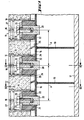
- Connection elements 6 are to be concreted into a filter floor 1 of a filter bed to be produced in the in-situ concrete, which are to be lined up at fixed intervals one behind the other in the longitudinal direction of a pure water collecting duct also to be concreted; only the ceiling formwork 17 is indicated by the channel.
- the individual connecting elements 6 are fastened to one another at an equal spacing A on a formwork body 15, for example made of steel or a reinforced, impact-resistant plastic; the formwork body 15 has a trapezoidal cross-section which widens downwards, which makes it easier to detach it after the concrete floor 1 has solidified.
- transverse stiffening walls 19 are attached between the brackets for the connecting elements 6.
- the brackets for the individual connecting elements 6 have supporting bolts 20 fastened in the formwork body 15, for example by welding or gluing, into which a thread 21 is cut from above.
- Cylindrical or barrel-shaped expansion bodies 22 are pushed over the support bolts 20, the height of which in the unloaded state, not shown, exceeds the height of the support bolts 20.
- cam-like projections 25 are fastened in alignment on the profile of the formwork body 15 between the described holders for the connecting elements 6 in the axial direction of the collecting duct to be created - likewise, for example, by welding or gluing .
- Corresponding grooves 26 are recessed at the lower edge of the connecting elements 6 to match the profile of these projections 25.
- the grooves 26 snap into the cams 25 and thus fix the connecting elements 6 with respect to a rotation about their axis, so that the threaded bores 16 are fixed relative to the axis of the collecting channel, for example, for all the connecting elements 6 at an equal angle of 90 0th
- the formwork body 15 is first fixed on the ceiling circuit 17 for the collecting duct. Then the connecting elements 6 are lined up on the still relaxed expansion bodies 22, the grooves 26 and the cams 25 intermeshing.
- the filter base 1 is produced by inserting the reinforcement, introducing and vibrating the concrete. After the concrete has solidified, the ceiling formwork 17 has been removed and the screws 24 have been loosened, the formwork body 15 can be removed downwards; it can then be used in the manner described for concreting a further section of the filter base 1.
- the invention is of course not limited to the exemplary embodiment shown. If, for example - as described in the aforementioned CH application - pipe clamps are attached to the filter base 1, the projections 27 with the threaded bores 16 are omitted on the flanges 10. The connecting elements 6 are then rotationally symmetrical without having a preferred direction. In this case, the cams 25 and the grooves 26 - as well as the projections 27 - of the described embodiment can be omitted.
Landscapes
- Chemical & Material Sciences (AREA)
- Chemical Kinetics & Catalysis (AREA)
- Forms Removed On Construction Sites Or Auxiliary Members Thereof (AREA)
- Filtration Of Liquid (AREA)
- Biological Treatment Of Waste Water (AREA)
- Moulds, Cores, Or Mandrels (AREA)
Abstract
Description
- Die Erfindung betrifft eine Vorrichtung zum vorübergehenden Fixieren von Verbindungselementen während ihres Einbetonierens in den Boden eines Filterfeldes einer Filteranlage, insbesondere für die Wasseraufbereitung, wobei in dem Filterfeld als Durchgangsorgane für das gefilterte Medium Filterdüsen vorhanden sind, die in einer Anzahl Drainagerohre aufgereiht sind, die ihrerseits im Bereich des betonierten Bodens des Filterfeldes mindestens annähernd parallel zueinander angeordnet und über je ein Anschlussrohr mit einem, unter dem Filterboden verlegten Sammelkanal für das abzuführende Filtrat verbunden sind.
- Für eine neuartige Montage der Drainagerohre am Boden eines Filterfeldes (P. 5425) müssen in den Filterboden Verbindungselemente einbetoniert werden, durch die im Filterboden Durchtrittsöffnungen zu einem darunter liegenden Sammelkanal für das Reinwasser entstehen. In diese Durchtrittsöffnungen werden die den Boden des Filterbodens bedeckenden Drainagerohre, die werkstattmässig vorgefertigt sind, mit Hilfe von an sie angesetzten Anschluss- oder Tauchrohren eingesteckt, nachdem der Filterboden fertiggestellt ist.
- Um die Montage der vorgefertigten Drainagerohre zu ermöglichen, müssen die Verbindungselemente mit relativ grosser Genauigkeit an vorbestimmten Stellen,des fertigen Filterbodens angeordnet sein. Der vorliegenden Erfindung liegt daher die Aufgabe zugrunde, eine Vorrichtung zu schaffen, mit der ein vorübergehendes Fixieren der Verbindungselemente bei der Herstellung des Filterbodens auf einfache Weise ermöglicht wird. Diese Aufgabe wird gelöst durch einen schlagfesten Schalungskörper, der in Richtung des Sammelkanals verläuft und in einem Abstand, der dem Abstand der zu verlegenden Drainagerohre entspricht, Tragbolzen für einen reversibel aufweitbaren Spreizkörper aufweist, ferner durch auf die Tragbolzen aufgesetzte Spreizkörper und durch Mittel zur individuellen, reversiblen Aufweitung der einzelnen Spreizkörper.
- Als Spreizkörper haben sich dabei mindestens annähernd inkompressible, tonnenartig geformte Elastomere bewährt, die durch in entsprechende Muttergewinde einschraubbare Schraubenbolzen in Achsrichtung zusammengepresst werden.
- Die erfindungsgemässe Vorrichtung gestattet eine genaue örtliche Festlegung der Verbindungselemente im Filterboden und insbesondere relativ zum Sammelkanal für das Reinwasser.
- Da die im allgemeinen rotationssymmetrischen, d.h. im wesentlichen in ihrem Querschnitt kreisförmigen Verbindungselemente unter Umständen eine Vorzugsrichtung haben, ist es zweckmässig, die richtige Lage dieser Vorzugsrichtung durch nockenartige Ansätze, die fluchtend hintereinander auf dem Schalungskörper zwischen dem Tragbolzen angeordnet sind, festzulegen. Die Steifigkeit des in Längsrichtung des Sammelkanals verlaufenden Schalungskörpers, der zweckmässigerweise ein domartiges Profil hat und auf die Deckenschalung für den Sammelkanal aufgesetzt werden kann, kann erhöht werden, wenn im Schalungskörper quer zu seiner Längsrichtung verlaufende Versteifungswände vorgesehen sind.
- Im folgenden wird die Erfindung anhand eines Ausführungsbeispieles im Zusammenhang mit der Zeichnung näher erläutert.
- Fig. 1 zeigt einen Schnitt I-I von Fig. 2, der in Längsrichtung des zu betonierenden Sammelkanals bzw. des Schalungskörpers verläuft;
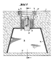
- Fig. 2 ist der Schnitt II-II von Fig. 1, während
- Fig. 3 den Schnitt III-III von Fig. 1 darstellt.
- In einen im Ortsbeton herzustellenden Filterboden 1 eines Filterbettes sind Verbindungselemente 6 einzubetonieren, die in festen Abständen hintereinander in Längsrichtung eines ebenfalls zu betonierenden Reinwassersammelkanals aufgereiht sein sollen; von dem Kanal ist nur die Deckenschalung 17 angedeutet.
- Die Verbindungselemente 6, die an sich kreisförmigen Querschnitt haben, tragen an ihrem oberen Ende einen flanschartigen Ansatz 10; in dem Ausführungsbeispiel hat dieser eine Vorzugsrichtung, da er diametral gegenüberliegende, nach aussen ragende Vorsprünge 27 mit Gewindebohrungen 16 aufweist, für die relativ zur Achsrichtung des Sammelkanals eine bestimmte gleiche Lage bei allen Verbindungselementen 6 eingehalten werden muss, die beispielsweise 90° zur Längsachse des Reinwasser-Sammelkanals beträgt.
- Die einzelnen Verbindungselemente 6 sind in gleichen Abständen A zueinander auf einem Schalungskörper 15, beispielsweise aus Stahl oder einem armierten schlagfesten Kunststoff, befestigt; der Schalungskörper 15 besitzt einen sich nach unten erweiternden, trapezförmigen Querschnitt, wodurch sein Herauslösen nach Erstarren des Betonbodens 1 erleichtert wird. In ihm sind zwischen den Halterungen für die Verbindungselemente 6 quer verlaufende Versteifungswände 19 angebracht. Die Halterungen für die einzelnen Verbindungselemente 6 haben in dem Schalungskörper 15, beispielsweise durch Schweissen oder Kleben, befestigte Tragbolzen 20, in die von oben ein Gewinde 21 eingeschnitten ist. Ueber die Tragbolzen 20 sind zylindrische oder tonnenförmige Spreizkörper 22 geschoben, deren Höhe im nicht dargestellten, unbelasteten Zustand die Höhe der Tragbolzen 20 übersteigt. Auf der ebenen Querschnittsfläche der Spreizkörper 22, die beispielsweise aus Weichgummi bestehen, liegt eine Scheibe 23 auf, die durch einen Schraubenbolzen 24, der in das Muttergewinde 21 eingreift, nach unten gezogen werden kann.
- Zur präzisen Festlegung der erwähnten ausgezeichneten Vorzugsrichtung für die Gewindebohrungen 16 im Flansch 10 sind auf dem Profil des Schalungskörpers 15 zwischen den beschriebenen Halterungen für die Verbindungselemente 6 nockenartige Vorsprünge 25 in Achsrichtung des zu schaffenden Sammelkanals fluchtend hintereinander verlaufend - ebenfalls beispielsweise durch Schweissen oder Kleben - befestigt. Auf das Profil dieser Vorsprünge 25 abgestimmt sind entsprechende Nuten 26 am unteren Rand der Verbindungselemente 6 ausgespart. Beim Aufsetzen der Verbindungselemente 6 auf den Schalungskörper 15 rasten die Nuten 26 in die Nocken 25 ein und fixieren so die Verbindungselemente 6 hinsichtlich einer Rotation um ihre Achse, so dass die Gewindebohrungen 16 relativ zur Achse des Sammelkanals beispielsweise für alle Verbindungselemente 6 unter einem gleichen Winkel von 900 fixiert sind.
- Für das Erstellen des Filterbodens 1 wird zunächst der Schalungskörper 15 auf der Deckenschaltung 17 für den Sammelkanal fixiert. Dann werden die Verbindungselemente 6 auf die noch entspannten Spreizkörper 22 aufgereiht, wobei die Nuten 26 und die Nocken 25 ineinandergreifen.
- Nach dem Fixieren der Verbindungselemente 6 mit Hilfe der von den Scheiben 23 und den Schraubenbolzen 24 zusammengepressten Spreizkörper 22 wird durch Einlegen der Armierung, Einbringen und Vibrieren des Betons der Filterboden 1 hergestellt. Nach dem Erstarren des Betons, dem Entfernen der Deckenschalung 17 und dem Lösen der Schrauben 24, lässt sich der Schalungskörper 15 nach unten herausnehmen; er kann in der beschriebenen Weise dann für das Betonieren eines weiteren Abschnittes des Filterbodens 1 verwendet werden.
- Die Erfindung ist selbstverständlich nicht auf das gezeigte Ausführungsbeispiel beschränkt. Werden beispielsweise - wie in der erwähnten CH-Anmeldung beschrieben - Rohrschellen auf dem Filterboden 1 befestigt, so entfallen an den Flanschen 10 die Vorsprünge 27 mit den Gewindebohrungen 16. Die Verbindungselemente 6 sind dann rotationssymmetrisch, ohne eine Vorzugsrichtung zu haben. In diesem Fall können daher die Nocken 25 und die Nuten 26 - ebenso wie die Vorsprünge 27 - des beschriebenen Ausführungsbeispieles entfallen.
Claims (5)
Priority Applications (1)
| Application Number | Priority Date | Filing Date | Title |
|---|---|---|---|
| AT79102988T ATE1538T1 (de) | 1979-05-31 | 1979-08-16 | Vorrichtung zum voruebergehenden fixieren von verbindungselementen fuer drainagerohre waehrend des einbetonierens in den boden eines filterfeldes. |
Applications Claiming Priority (2)
| Application Number | Priority Date | Filing Date | Title |
|---|---|---|---|
| CH5084/79 | 1979-05-31 | ||
| CH508479A CH636399A5 (de) | 1979-05-31 | 1979-05-31 | Vorrichtung zum voruebergehenden fixieren von verbindungselementen fuer drainagerohre waehrend des einbetonierens in den boden eines filterfeldes. |
Publications (2)
| Publication Number | Publication Date |
|---|---|
| EP0019655A1 true EP0019655A1 (de) | 1980-12-10 |
| EP0019655B1 EP0019655B1 (de) | 1982-09-15 |
Family
ID=4287670
Family Applications (1)
| Application Number | Title | Priority Date | Filing Date |
|---|---|---|---|
| EP79102988A Expired EP0019655B1 (de) | 1979-05-31 | 1979-08-16 | Vorrichtung zum vorübergehenden Fixieren von Verbindungselementen für Drainagerohre während des Einbetonierens in den Boden eines Filterfeldes |
Country Status (4)
| Country | Link |
|---|---|
| EP (1) | EP0019655B1 (de) |
| AT (1) | ATE1538T1 (de) |
| CH (1) | CH636399A5 (de) |
| DE (1) | DE2963678D1 (de) |
Cited By (6)
| Publication number | Priority date | Publication date | Assignee | Title |
|---|---|---|---|---|
| EP0094487A1 (de) * | 1982-03-30 | 1983-11-23 | MERCK PATENT GmbH | Hydroterphenyle, ihre Herstellung und Verwendung für flüssigkristalline Dielektrika |
| EP0104263A3 (en) * | 1982-09-02 | 1986-06-11 | Gebruder Sulzer Aktiengesellschaft | Device for the fixation of drain pipes |
| FR2641588A1 (fr) * | 1989-01-09 | 1990-07-13 | Degremont | Dispositif pour la mise en place et la fixation, sur le plancher d'un filtre, d'organes assurant le transit de fluides a travers le plancher |
| EP0698407A1 (de) * | 1994-08-26 | 1996-02-28 | Sulzer Chemtech AG | Abwasserbehandlungsreaktor mit Düsenboden |
| WO2021024107A1 (en) * | 2019-08-02 | 2021-02-11 | Tyco Fire Products Lp | Sprinkler box for embedded sprinkler pipe system |
| US10937285B2 (en) | 2018-06-01 | 2021-03-02 | Johnson Controls Fire Protection LP | Systems and methods of alarm controls and directed audio evacuation |
Families Citing this family (1)
| Publication number | Priority date | Publication date | Assignee | Title |
|---|---|---|---|---|
| AT391044B (de) * | 1987-09-09 | 1990-08-10 | Doepfl Rudolf Gmbh | Einrichtung zur pressung von in einem rahmen befindlichen packstuecken zur herstellung von kabeldurchfuehrungen |
Citations (4)
| Publication number | Priority date | Publication date | Assignee | Title |
|---|---|---|---|---|
| FR1013722A (fr) * | 1950-01-13 | 1952-08-04 | Trailigaz | Perfectionnements à la réalisation des filtres à sable |
| GB888202A (en) * | 1959-08-20 | 1962-01-31 | Alexander Feldmann | Improvements relating to means and methods of forming anchoring cavities in cast materials and to anchoring bolts for use therein |
| FR1405568A (fr) * | 1963-08-15 | 1965-07-09 | Sulzer Ag | Procédé de fabrication de fonds de filtre en béton, et fonds en résultant |
| US4159099A (en) * | 1977-05-09 | 1979-06-26 | Maguire James V | Sleeve assembly for forming openings in molded structures |
-
1979
- 1979-05-31 CH CH508479A patent/CH636399A5/de not_active IP Right Cessation
- 1979-08-16 EP EP79102988A patent/EP0019655B1/de not_active Expired
- 1979-08-16 DE DE7979102988T patent/DE2963678D1/de not_active Expired
- 1979-08-16 AT AT79102988T patent/ATE1538T1/de not_active IP Right Cessation
Patent Citations (4)
| Publication number | Priority date | Publication date | Assignee | Title |
|---|---|---|---|---|
| FR1013722A (fr) * | 1950-01-13 | 1952-08-04 | Trailigaz | Perfectionnements à la réalisation des filtres à sable |
| GB888202A (en) * | 1959-08-20 | 1962-01-31 | Alexander Feldmann | Improvements relating to means and methods of forming anchoring cavities in cast materials and to anchoring bolts for use therein |
| FR1405568A (fr) * | 1963-08-15 | 1965-07-09 | Sulzer Ag | Procédé de fabrication de fonds de filtre en béton, et fonds en résultant |
| US4159099A (en) * | 1977-05-09 | 1979-06-26 | Maguire James V | Sleeve assembly for forming openings in molded structures |
Cited By (9)
| Publication number | Priority date | Publication date | Assignee | Title |
|---|---|---|---|---|
| EP0094487A1 (de) * | 1982-03-30 | 1983-11-23 | MERCK PATENT GmbH | Hydroterphenyle, ihre Herstellung und Verwendung für flüssigkristalline Dielektrika |
| EP0104263A3 (en) * | 1982-09-02 | 1986-06-11 | Gebruder Sulzer Aktiengesellschaft | Device for the fixation of drain pipes |
| FR2641588A1 (fr) * | 1989-01-09 | 1990-07-13 | Degremont | Dispositif pour la mise en place et la fixation, sur le plancher d'un filtre, d'organes assurant le transit de fluides a travers le plancher |
| EP0378024A1 (de) * | 1989-01-09 | 1990-07-18 | Degremont S.A. | Vorrichtung zum Plazieren und Befestigen von Teilen auf einem Filterboden, wobei die Teile den Durchgang von Fluiden durch diesen Filterboden sicherstellen |
| US5087361A (en) * | 1989-01-09 | 1992-02-11 | Degremont | Filter floor nozzle housing and support arrangement |
| EP0698407A1 (de) * | 1994-08-26 | 1996-02-28 | Sulzer Chemtech AG | Abwasserbehandlungsreaktor mit Düsenboden |
| US10937285B2 (en) | 2018-06-01 | 2021-03-02 | Johnson Controls Fire Protection LP | Systems and methods of alarm controls and directed audio evacuation |
| WO2021024107A1 (en) * | 2019-08-02 | 2021-02-11 | Tyco Fire Products Lp | Sprinkler box for embedded sprinkler pipe system |
| US12239866B2 (en) | 2019-08-02 | 2025-03-04 | Tyco Fire Products Lp | Sprinkler box for embedded sprinkler pipe system |
Also Published As
| Publication number | Publication date |
|---|---|
| EP0019655B1 (de) | 1982-09-15 |
| DE2963678D1 (en) | 1982-11-04 |
| CH636399A5 (de) | 1983-05-31 |
| ATE1538T1 (de) | 1982-09-15 |
Similar Documents
| Publication | Publication Date | Title |
|---|---|---|
| EP0119652A2 (de) | Verbindungs- und Druckverteilungselement für Betonbauteile | |
| DE1958112C3 (de) | ||
| DE3224986C2 (de) | Vorrichtung zur Befestigung von Montageteilen an einer Betonwand | |
| DE2554855A1 (de) | Stuetzkragen fuer baugerueste | |
| WO1988002049A1 (en) | Device for fixing tubular assembly elements | |
| EP0019655B1 (de) | Vorrichtung zum vorübergehenden Fixieren von Verbindungselementen für Drainagerohre während des Einbetonierens in den Boden eines Filterfeldes | |
| EP1757742A2 (de) | Rigolenelement mit Inspektionskanal | |
| DE19607254C2 (de) | Hohlkörper für die Betonbauinstallation | |
| DE2422658B1 (de) | Wassereinlauf zur Entwässerung von Flachdächern, Baikonen, Terrassen od. dgl | |
| DE2823417C3 (de) | Schachtauskleidung zur Verwendung beim Aufwärtsbohren eines Schachtes und Schachtring für eine derartige Schachtauskleidung | |
| AT411079B (de) | Verfahren zur errichtung eines bauwerks mit einer umfangsgeschlossenen betonwand | |
| DE2800868A1 (de) | Befestigungsanordnung fuer foerderband-reinigungsvorrichtungen | |
| DE69200537T2 (de) | Herstellungsverfahren für Trennvorrichtungen. | |
| WO1998036885A1 (de) | Schalungssystem für betonfertigteile | |
| DE3508706A1 (de) | Aussparungskoerper | |
| DE3882532T2 (de) | Konstruktionsmethode für betonpfeiler für eine plattform oder ähnliche konstruktionen. | |
| DE3044232A1 (de) | Silobehaelter | |
| DE102009049178A1 (de) | Schalung | |
| DE2532964C2 (de) | Verfahren zum Herstellen sowie zum Manipulieren eines großformatigen Wand-Fertigbauteils | |
| DE2703583A1 (de) | Entwaesserungsrinne fuer begeh- und/oder befahrbare flaechen | |
| DE10305469A1 (de) | Brückenablauf | |
| DE2703379C2 (de) | Belebtschlammanlage zur Abwasserreinigung | |
| CH639720A5 (en) | Panel ceiling | |
| EP0104263B1 (de) | Vorrichtung zur Fixierung von Drainagerohren | |
| EP1435416A1 (de) | Entwässerungsrinne sowie Verfahren zum Herstellen einer solchen Entwässerungsrinne |
Legal Events
| Date | Code | Title | Description |
|---|---|---|---|
| PUAI | Public reference made under article 153(3) epc to a published international application that has entered the european phase |
Free format text: ORIGINAL CODE: 0009012 |
|
| 17P | Request for examination filed | ||
| AK | Designated contracting states |
Designated state(s): AT DE FR GB IT NL |
|
| ITF | It: translation for a ep patent filed | ||
| GRAA | (expected) grant |
Free format text: ORIGINAL CODE: 0009210 |
|
| AK | Designated contracting states |
Designated state(s): AT DE FR GB IT NL |
|
| REF | Corresponds to: |
Ref document number: 1538 Country of ref document: AT Date of ref document: 19820915 Kind code of ref document: T |
|
| REF | Corresponds to: |
Ref document number: 2963678 Country of ref document: DE Date of ref document: 19821104 |
|
| PGFP | Annual fee paid to national office [announced via postgrant information from national office to epo] |
Ref country code: FR Payment date: 19840621 Year of fee payment: 6 |
|
| PGFP | Annual fee paid to national office [announced via postgrant information from national office to epo] |
Ref country code: DE Payment date: 19840824 Year of fee payment: 6 |
|
| PGFP | Annual fee paid to national office [announced via postgrant information from national office to epo] |
Ref country code: AT Payment date: 19850819 Year of fee payment: 7 |
|
| PGFP | Annual fee paid to national office [announced via postgrant information from national office to epo] |
Ref country code: NL Payment date: 19850831 Year of fee payment: 7 |
|
| PG25 | Lapsed in a contracting state [announced via postgrant information from national office to epo] |
Ref country code: AT Effective date: 19860816 |
|
| PG25 | Lapsed in a contracting state [announced via postgrant information from national office to epo] |
Ref country code: NL Effective date: 19870301 |
|
| NLV4 | Nl: lapsed or anulled due to non-payment of the annual fee | ||
| GBPC | Gb: european patent ceased through non-payment of renewal fee | ||
| PG25 | Lapsed in a contracting state [announced via postgrant information from national office to epo] |
Ref country code: FR Free format text: LAPSE BECAUSE OF NON-PAYMENT OF DUE FEES Effective date: 19870430 |
|
| PG25 | Lapsed in a contracting state [announced via postgrant information from national office to epo] |
Ref country code: DE Effective date: 19870501 |
|
| REG | Reference to a national code |
Ref country code: FR Ref legal event code: ST |
|
| PG25 | Lapsed in a contracting state [announced via postgrant information from national office to epo] |
Ref country code: GB Effective date: 19881118 |
|
| PLBE | No opposition filed within time limit |
Free format text: ORIGINAL CODE: 0009261 |
|
| STAA | Information on the status of an ep patent application or granted ep patent |
Free format text: STATUS: NO OPPOSITION FILED WITHIN TIME LIMIT |