EP0019663A2 - Coal gasifying burner - Google Patents
Coal gasifying burner Download PDFInfo
- Publication number
- EP0019663A2 EP0019663A2 EP79104903A EP79104903A EP0019663A2 EP 0019663 A2 EP0019663 A2 EP 0019663A2 EP 79104903 A EP79104903 A EP 79104903A EP 79104903 A EP79104903 A EP 79104903A EP 0019663 A2 EP0019663 A2 EP 0019663A2
- Authority
- EP
- European Patent Office
- Prior art keywords
- coal
- burner
- grill
- combustion
- side walls
- Prior art date
- Legal status (The legal status is an assumption and is not a legal conclusion. Google has not performed a legal analysis and makes no representation as to the accuracy of the status listed.)
- Withdrawn
Links
Images


Classifications
-
- F—MECHANICAL ENGINEERING; LIGHTING; HEATING; WEAPONS; BLASTING
- F23—COMBUSTION APPARATUS; COMBUSTION PROCESSES
- F23M—CASINGS, LININGS, WALLS OR DOORS SPECIALLY ADAPTED FOR COMBUSTION CHAMBERS, e.g. FIREBRIDGES; DEVICES FOR DEFLECTING AIR, FLAMES OR COMBUSTION PRODUCTS IN COMBUSTION CHAMBERS; SAFETY ARRANGEMENTS SPECIALLY ADAPTED FOR COMBUSTION APPARATUS; DETAILS OF COMBUSTION CHAMBERS, NOT OTHERWISE PROVIDED FOR
- F23M5/00—Casings; Linings; Walls
- F23M5/08—Cooling thereof; Tube walls
-
- C—CHEMISTRY; METALLURGY
- C10—PETROLEUM, GAS OR COKE INDUSTRIES; TECHNICAL GASES CONTAINING CARBON MONOXIDE; FUELS; LUBRICANTS; PEAT
- C10J—PRODUCTION OF PRODUCER GAS, WATER-GAS, SYNTHESIS GAS FROM SOLID CARBONACEOUS MATERIAL, OR MIXTURES CONTAINING THESE GASES; CARBURETTING AIR OR OTHER GASES
- C10J3/00—Production of combustible gases containing carbon monoxide from solid carbonaceous fuels
- C10J3/02—Fixed-bed gasification of lump fuel
- C10J3/06—Continuous processes
- C10J3/08—Continuous processes with ash-removal in liquid state
-
- C—CHEMISTRY; METALLURGY
- C10—PETROLEUM, GAS OR COKE INDUSTRIES; TECHNICAL GASES CONTAINING CARBON MONOXIDE; FUELS; LUBRICANTS; PEAT
- C10J—PRODUCTION OF PRODUCER GAS, WATER-GAS, SYNTHESIS GAS FROM SOLID CARBONACEOUS MATERIAL, OR MIXTURES CONTAINING THESE GASES; CARBURETTING AIR OR OTHER GASES
- C10J3/00—Production of combustible gases containing carbon monoxide from solid carbonaceous fuels
- C10J3/02—Fixed-bed gasification of lump fuel
- C10J3/20—Apparatus; Plants
- C10J3/30—Fuel charging devices
-
- C—CHEMISTRY; METALLURGY
- C10—PETROLEUM, GAS OR COKE INDUSTRIES; TECHNICAL GASES CONTAINING CARBON MONOXIDE; FUELS; LUBRICANTS; PEAT
- C10J—PRODUCTION OF PRODUCER GAS, WATER-GAS, SYNTHESIS GAS FROM SOLID CARBONACEOUS MATERIAL, OR MIXTURES CONTAINING THESE GASES; CARBURETTING AIR OR OTHER GASES
- C10J3/00—Production of combustible gases containing carbon monoxide from solid carbonaceous fuels
- C10J3/02—Fixed-bed gasification of lump fuel
- C10J3/20—Apparatus; Plants
- C10J3/32—Devices for distributing fuel evenly over the bed or for stirring up the fuel bed
-
- C—CHEMISTRY; METALLURGY
- C10—PETROLEUM, GAS OR COKE INDUSTRIES; TECHNICAL GASES CONTAINING CARBON MONOXIDE; FUELS; LUBRICANTS; PEAT
- C10J—PRODUCTION OF PRODUCER GAS, WATER-GAS, SYNTHESIS GAS FROM SOLID CARBONACEOUS MATERIAL, OR MIXTURES CONTAINING THESE GASES; CARBURETTING AIR OR OTHER GASES
- C10J3/00—Production of combustible gases containing carbon monoxide from solid carbonaceous fuels
- C10J3/02—Fixed-bed gasification of lump fuel
- C10J3/20—Apparatus; Plants
- C10J3/34—Grates; Mechanical ash-removing devices
- C10J3/40—Movable grates
- C10J3/42—Rotary grates
-
- C—CHEMISTRY; METALLURGY
- C10—PETROLEUM, GAS OR COKE INDUSTRIES; TECHNICAL GASES CONTAINING CARBON MONOXIDE; FUELS; LUBRICANTS; PEAT
- C10J—PRODUCTION OF PRODUCER GAS, WATER-GAS, SYNTHESIS GAS FROM SOLID CARBONACEOUS MATERIAL, OR MIXTURES CONTAINING THESE GASES; CARBURETTING AIR OR OTHER GASES
- C10J3/00—Production of combustible gases containing carbon monoxide from solid carbonaceous fuels
- C10J3/72—Other features
- C10J3/74—Construction of shells or jackets
- C10J3/76—Water jackets; Steam boiler-jackets
-
- F—MECHANICAL ENGINEERING; LIGHTING; HEATING; WEAPONS; BLASTING
- F23—COMBUSTION APPARATUS; COMBUSTION PROCESSES
- F23B—METHODS OR APPARATUS FOR COMBUSTION USING ONLY SOLID FUEL
- F23B1/00—Combustion apparatus using only lump fuel
- F23B1/16—Combustion apparatus using only lump fuel the combustion apparatus being modified according to the form of grate or other fuel support
- F23B1/165—Combustion apparatus using only lump fuel the combustion apparatus being modified according to the form of grate or other fuel support using roller grate
-
- F—MECHANICAL ENGINEERING; LIGHTING; HEATING; WEAPONS; BLASTING
- F23—COMBUSTION APPARATUS; COMBUSTION PROCESSES
- F23B—METHODS OR APPARATUS FOR COMBUSTION USING ONLY SOLID FUEL
- F23B90/00—Combustion methods not related to a particular type of apparatus
- F23B90/04—Combustion methods not related to a particular type of apparatus including secondary combustion
- F23B90/06—Combustion methods not related to a particular type of apparatus including secondary combustion the primary combustion being a gasification or pyrolysis in a reductive atmosphere
-
- F—MECHANICAL ENGINEERING; LIGHTING; HEATING; WEAPONS; BLASTING
- F23—COMBUSTION APPARATUS; COMBUSTION PROCESSES
- F23H—GRATES; CLEANING OR RAKING GRATES
- F23H15/00—Cleaning arrangements for grates; Moving fuel along grates
-
- F—MECHANICAL ENGINEERING; LIGHTING; HEATING; WEAPONS; BLASTING
- F23—COMBUSTION APPARATUS; COMBUSTION PROCESSES
- F23J—REMOVAL OR TREATMENT OF COMBUSTION PRODUCTS OR COMBUSTION RESIDUES; FLUES
- F23J1/00—Removing ash, clinker, or slag from combustion chambers
-
- C—CHEMISTRY; METALLURGY
- C10—PETROLEUM, GAS OR COKE INDUSTRIES; TECHNICAL GASES CONTAINING CARBON MONOXIDE; FUELS; LUBRICANTS; PEAT
- C10J—PRODUCTION OF PRODUCER GAS, WATER-GAS, SYNTHESIS GAS FROM SOLID CARBONACEOUS MATERIAL, OR MIXTURES CONTAINING THESE GASES; CARBURETTING AIR OR OTHER GASES
- C10J2300/00—Details of gasification processes
- C10J2300/09—Details of the feed, e.g. feeding of spent catalyst, inert gas or halogens
- C10J2300/0913—Carbonaceous raw material
- C10J2300/093—Coal
-
- C—CHEMISTRY; METALLURGY
- C10—PETROLEUM, GAS OR COKE INDUSTRIES; TECHNICAL GASES CONTAINING CARBON MONOXIDE; FUELS; LUBRICANTS; PEAT
- C10J—PRODUCTION OF PRODUCER GAS, WATER-GAS, SYNTHESIS GAS FROM SOLID CARBONACEOUS MATERIAL, OR MIXTURES CONTAINING THESE GASES; CARBURETTING AIR OR OTHER GASES
- C10J2300/00—Details of gasification processes
- C10J2300/09—Details of the feed, e.g. feeding of spent catalyst, inert gas or halogens
- C10J2300/0953—Gasifying agents
- C10J2300/0956—Air or oxygen enriched air
Definitions
- This invention relates to a coal gasifying burner comprising a coal storage, a combustion cell, a burner nozzle and a grill.
- the object of the invention is to provide a coal gasifying burner having an efficient combustion of bitimuous coal and lignites which can be easily operated automatically.
- a coal gasifying burner comprising a coal storage, a combustion cell, a burner nozzle and a grill is characterized in that one or more narrow gaps having rounded edges are provided between the coal storage and the combustion cell for a continuous coal flow from the coal storage to the combustion cell, that an air isolated partition is placed on a roof which separates the combustion cell from the coal storage, that the side walls determing the passage of coal from the coal storage to the combustion cell are made of metal sheet sloped under an angle compatible with the coal flow and that a cylinder for introduction of combustion air into the burner surrounds the burner nozzle, excessive coal located on the sloping side walls in a small area around the place where coal combustion takes place being gasified, the gases escaping thereby being burnt outside of the burner by secondary air which cools the coal gasifying burner and is heated itself by the cooling process.
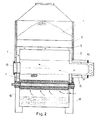
- the coal moves, as shown in Figure 1, from the coal storage 1 formed .by the upper portion of the burner into the combustion cell 2 through narrow gaps or passages 3 which determine the thickness of the coal layer.
- the edges of these passages 3 are rounded to enable a continuous coal flow. Due to the narrow passages 3 whose edges have been rounded, coal flows down from above by gravity in an amount equal to that burnt on the grill 9.
- a part 4 which is called the roof separates the combustion cell 2 from the coal storage 1 (see Figure 1) and mainly consists of two layers through which secondary air circulates (see Figure 2).
- the secondary air cools the roof and thus is heated itself. This heating up in turn would heat up the coal on top edge of the roof thus causing the water in the coal to evaporate and the volatile components in the coal to escape in a certain amount. This evaportation of water and volatilization of gases would disturb the coal flow and could cause explosions in the coal storage. Therefore, to prevent heat transfer from the roof to the coal storage, an air isolated partition 5 is provided on the upper face of the roof, as shown in Figure 1.
- the front and back walls 7 as well as the side walls 6 of the combustion cell 2, in other words the parts where burning actually takes place and intense heat is generated, are cooled down with water.
- the grill 9 shown in Figures 1 and 2 comprises two hollow shafts each having a plurality of grill discs 10. Between the two grill cylinders thus formed there is a very narrow gap 11. When viewed from the top, the grill cylinders rotate very slowly towards the interior in dependance of control commands delivered from a boiler or a furnace. The grill cylinders stop upon receipt of a corresponding control command. By the aid of such a grill type it is possible to provide for a continuous burning of high quality without any drop of unburnt coal onto the ash tray 12.
- the ash tray 12 which is located below the grill 9 is attached to the body of the burner by steel profiles 14.
- the grill system can be easily removed for maintenance and repair work.
- the bottom of the ash tray 12 is siphon-like shaped, as shown in Figure 1, the ash tray being partly filled with water.
- ash and slag can be taken out of the ash tray 12 without introducing cold air into the burner which would cool down the system and cause a drop down in the efficiency.
- the combustion air of the burner is delivered to the system by a cylinder or jacket 15 fitted around the burner nozzle, after which the combustion air is divided into a primary and secondary air.
- a cylinder or jacket 15 fitted around the burner nozzle, after which the combustion air is divided into a primary and secondary air.
- Combs 16 designed such to fit between the grill discs, as shown in Figure 1, are mounted on the grill system 9 to remove the slag left between the grill discs. Long holes are drilled into the sides of the ash tray to facilitate maintenance and repair of the combs which are carried by steel profiles.
- the coal gasifying burner with rotating grill cylinders according to the invention can be operated automatically and with an efficiency (85 - 90 %) which is as high as that of fuel oil burner. Moreover, the operation of the burner is involved with less pollution (quantity of smoke measured in the chimney is Bacharach 0-3).
- the coal gasifying burner having rotating grill cylinders,as shown in the Figures,and described above, can have a capacity suitable for heating a very small apartment flat (100000 kcal/h) as well as a capacity suitable for heating very big industrial complexes (20,25000000 kcal/h).
Landscapes
- Engineering & Computer Science (AREA)
- Chemical & Material Sciences (AREA)
- Combustion & Propulsion (AREA)
- Mechanical Engineering (AREA)
- Oil, Petroleum & Natural Gas (AREA)
- Organic Chemistry (AREA)
- General Engineering & Computer Science (AREA)
- Physics & Mathematics (AREA)
- Thermal Sciences (AREA)
- Solid-Fuel Combustion (AREA)
Abstract
A coal gasifying burner has a rotating grill comprising two grill cylinders (9) spaced from each other by a narrow gap (11). Each grill cylinder mainly consists of a shaft on which a plurality of discs (10) is mounted. The grill cylinders rotate very slowly inwards when viewed from the top. Side walls (6) made of metal sheet are sloped in compliance with the coal flow from a coal storage (1) to a combustion cell (2). A cylinder (15) surrounding the burner nozzle introduces the combustion air. The exces- sive coal located on the sloping side walls in the vicinity of the combustion of coal is gasified and the gases generated thereby are burnt outside of the burner with secondary air which has been introduced into the coal gasifying burner for cooling it and has thereby been heated itself.
Description
- This invention relates to a coal gasifying burner comprising a coal storage, a combustion cell, a burner nozzle and a grill.
- The object of the invention is to provide a coal gasifying burner having an efficient combustion of bitimuous coal and lignites which can be easily operated automatically.
- In principal the coal is burnt on a narrow rotating grill. The gas escaping from the excessive coal at the sides of the rotating grill is burnt outside of the burner by the aid of air which cools the combustion cell and thus is heated during this process.
- In detail, according to the invention, a coal gasifying burner comprising a coal storage, a combustion cell, a burner nozzle and a grill is characterized in that one or more narrow gaps having rounded edges are provided between the coal storage and the combustion cell for a continuous coal flow from the coal storage to the combustion cell, that an air isolated partition is placed on a roof which separates the combustion cell from the coal storage, that the side walls determing the passage of coal from the coal storage to the combustion cell are made of metal sheet sloped under an angle compatible with the coal flow and that a cylinder for introduction of combustion air into the burner surrounds the burner nozzle, excessive coal located on the sloping side walls in a small area around the place where coal combustion takes place being gasified, the gases escaping thereby being burnt outside of the burner by secondary air which cools the coal gasifying burner and is heated itself by the cooling process.
- One way of carrying out the invention is described in detail below with reference to drawings which illustrate only one specific embodiment, in which:-
- Figure 1 is a cross-sectional view of the coal gasifying burner having a rotating grill in accordance with the invention,
- Figure 2 is a cross-section taken on the line A-A in Figure 1,
- Figure 3a is a cross-section of a disc of a grill cylinder according to the invention,
- Figure 3b is a side view of the disc shown in Figure 3a, and
- Figures 3c and 3d are different side views of the grill cylinders according to the invention.
- The coal moves, as shown in Figure 1, from the
coal storage 1 formed .by the upper portion of the burner into thecombustion cell 2 through narrow gaps orpassages 3 which determine the thickness of the coal layer. The edges of thesepassages 3 are rounded to enable a continuous coal flow. Due to thenarrow passages 3 whose edges have been rounded, coal flows down from above by gravity in an amount equal to that burnt on thegrill 9. - A part 4 which is called the roof separates the
combustion cell 2 from the coal storage 1 (see Figure 1) and mainly consists of two layers through which secondary air circulates (see Figure 2). The secondary air cools the roof and thus is heated itself. This heating up in turn would heat up the coal on top edge of the roof thus causing the water in the coal to evaporate and the volatile components in the coal to escape in a certain amount. This evaportation of water and volatilization of gases would disturb the coal flow and could cause explosions in the coal storage. Therefore, to prevent heat transfer from the roof to the coal storage, an airisolated partition 5 is provided on the upper face of the roof, as shown in Figure 1. - It has been observed that, if the side walls of the combustion cell are lined with refractory stones coal particles stick to these stones which would also disturb the continuous flow of coal into the combustion cell. Therefore, the side walls are made of sheet sloped under such an angle that the desired coal flow is obtained and refractory stones are not used.
- The front and
back walls 7 as well as theside walls 6 of thecombustion cell 2, in other words the parts where burning actually takes place and intense heat is generated, are cooled down with water. - In order to achieve an automatic operation of the burner under a thermostatic control, a new grill type has been developed. The
grill 9 shown in Figures 1 and 2 comprises two hollow shafts each having a plurality ofgrill discs 10. Between the two grill cylinders thus formed there is a verynarrow gap 11. When viewed from the top, the grill cylinders rotate very slowly towards the interior in dependance of control commands delivered from a boiler or a furnace. The grill cylinders stop upon receipt of a corresponding control command. By the aid of such a grill type it is possible to provide for a continuous burning of high quality without any drop of unburnt coal onto theash tray 12. Since the ash and slag are automatically disposed onto theash tray 12 there is no need to open thelid 13 in front of the burner, except in times of operational problems, to unload ash and slag. Therefore, introduction of cold air into the system which reduces the efficiency is avoided. - The
ash tray 12 which is located below thegrill 9 is attached to the body of the burner by steel profiles 14. Thus, the grill system can be easily removed for maintenance and repair work. - The bottom of the
ash tray 12 is siphon-like shaped, as shown in Figure 1, the ash tray being partly filled with water. Thus, ash and slag can be taken out of theash tray 12 without introducing cold air into the burner which would cool down the system and cause a drop down in the efficiency. - The combustion air of the burner is delivered to the system by a cylinder or
jacket 15 fitted around the burner nozzle, after which the combustion air is divided into a primary and secondary air. By way of introducing the initial air around the nozzle periphery, the heat loss from the nozzle is returned to the system, thus increasing the efficiency. -
Combs 16 designed such to fit between the grill discs, as shown in Figure 1, are mounted on thegrill system 9 to remove the slag left between the grill discs. Long holes are drilled into the sides of the ash tray to facilitate maintenance and repair of the combs which are carried by steel profiles. - As can be clearly understood from the explanations given above, the coal gasifying burner with rotating grill cylinders according to the invention can be operated automatically and with an efficiency (85 - 90 %) which is as high as that of fuel oil burner. Moreover, the operation of the burner is involved with less pollution (quantity of smoke measured in the chimney is Bacharach 0-3).
- The coal gasifying burner having rotating grill cylinders,as shown in the Figures,and described above, can have a capacity suitable for heating a very small apartment flat (100000 kcal/h) as well as a capacity suitable for heating very big industrial complexes (20,25000000 kcal/h).
Claims (4)
1. Coal gasifying burner comprising a coal storage (1), a combustion cell (2), a burner nozzle and a grill (9), characterized in
that one or more narrow gaps (3) having rounded edges are provided between the coal storage (1) and the combustion cell for a continuous coal flow from the coal storage (1) to the combustion cell (2), that an air isolated partition is placed on a roof (4) which separates the combustion cell (2) from the coal storage (1), that the side walls (6, 7) determing the passage of coal from the coal storage (1) to the combustion cell are made of metal sheet sloped under an angle compatible with the coal flow and that a cylinder (15) for introduction of combustion air into the burner surrounds the burner nozzle, excessive coal located on the sloping side walls in a small area around the place where coal combustion takes place being gasified, the gases escaping thereby being burnt outside of the burner by secondary air which cools the coal gasifying burner and is heated itself by the cooling process.
that one or more narrow gaps (3) having rounded edges are provided between the coal storage (1) and the combustion cell for a continuous coal flow from the coal storage (1) to the combustion cell (2), that an air isolated partition is placed on a roof (4) which separates the combustion cell (2) from the coal storage (1), that the side walls (6, 7) determing the passage of coal from the coal storage (1) to the combustion cell are made of metal sheet sloped under an angle compatible with the coal flow and that a cylinder (15) for introduction of combustion air into the burner surrounds the burner nozzle, excessive coal located on the sloping side walls in a small area around the place where coal combustion takes place being gasified, the gases escaping thereby being burnt outside of the burner by secondary air which cools the coal gasifying burner and is heated itself by the cooling process.
2. Coal gasifying burner according to claim 1, characterized in
that two grill cylinders (9) each comprising a shaft and a plurality of discs (10) mounted on the shaft are spaced from another by a narrow gap (11) and rotate very slowly inwards when viewed from the top for maintaining combustion without any drop of unburnt coal onto an ash tray (12) disposed below the grill cylinders (9), and in that combs (16) are provided for cleaning the grill cylinders (9) from the slag.
that two grill cylinders (9) each comprising a shaft and a plurality of discs (10) mounted on the shaft are spaced from another by a narrow gap (11) and rotate very slowly inwards when viewed from the top for maintaining combustion without any drop of unburnt coal onto an ash tray (12) disposed below the grill cylinders (9), and in that combs (16) are provided for cleaning the grill cylinders (9) from the slag.
3. Coal gasifying burner according to claim 1 or 2, characterized in
that the ash tray (12) is shipon-like shaped and filled with water.
that the ash tray (12) is shipon-like shaped and filled with water.
4. Coal gasifying burner according to one of the claims 1 to 3,
characterized in
that the side walls (7, 6) are water cooled.
characterized in
that the side walls (7, 6) are water cooled.
Applications Claiming Priority (2)
| Application Number | Priority Date | Filing Date | Title |
|---|---|---|---|
| TR10184/78 | 1978-12-07 | ||
| TR1018478 | 1978-12-07 |
Publications (2)
| Publication Number | Publication Date |
|---|---|
| EP0019663A2 true EP0019663A2 (en) | 1980-12-10 |
| EP0019663A3 EP0019663A3 (en) | 1981-01-07 |
Family
ID=21619342
Family Applications (1)
| Application Number | Title | Priority Date | Filing Date |
|---|---|---|---|
| EP19790104903 Withdrawn EP0019663A3 (en) | 1978-12-07 | 1979-12-04 | Coal gasifying burner |
Country Status (2)
| Country | Link |
|---|---|
| US (1) | US4274341A (en) |
| EP (1) | EP0019663A3 (en) |
Cited By (5)
| Publication number | Priority date | Publication date | Assignee | Title |
|---|---|---|---|---|
| FR2500585A1 (en) * | 1981-02-20 | 1982-08-27 | Madrias Rene | Multi-fuel water or steam boiler - has double=walled hearth and radiator in dust separator for additional heating of water |
| WO1984004577A1 (en) * | 1983-05-18 | 1984-11-22 | Elf France | Method and boiler hearth for the desulphuration of fuel gas |
| FR2608736A1 (en) * | 1986-06-16 | 1988-06-24 | Meca Reparation Const | Central heating boiler burning solid fuel |
| EP0410363A3 (en) * | 1989-07-26 | 1991-07-31 | Forschungszentrum Juelich Gmbh | Gasification reactor for combustible solids |
| CN109370659A (en) * | 2018-11-27 | 2019-02-22 | 方忠平 | A kind of powder coal gasification furnace with storage device for coal |
Families Citing this family (8)
| Publication number | Priority date | Publication date | Assignee | Title |
|---|---|---|---|---|
| FR2517025A1 (en) * | 1981-11-25 | 1983-05-27 | Fives Cail Babcock | INSTALLATION OF SOLID FUEL BOILER |
| DE3317977A1 (en) * | 1983-05-18 | 1984-11-22 | Pka Pyrolyse Kraftanlagen Gmbh, 7080 Aalen | GAS CONVERTER |
| US4531464A (en) * | 1984-07-20 | 1985-07-30 | Eshland Enterprises, Inc. | Particle fuel diversion structure |
| US4598649A (en) * | 1985-09-03 | 1986-07-08 | Eshland Enterprises, Inc. | Particle fuel diversion structure with dome-shaped cavity |
| ATE81195T1 (en) * | 1986-08-08 | 1992-10-15 | Clinton Badger Pike | OVEN. |
| US4764185A (en) * | 1987-10-28 | 1988-08-16 | Mayer Edward F | Gasifier apparatus |
| US6929001B2 (en) * | 2003-10-20 | 2005-08-16 | Cheol Jung Yoon | Rotating barbecue grill |
| ITVI20060060A1 (en) * | 2006-03-08 | 2007-09-09 | B & B Elevators Srl | COMBUSTION CHAMBER |
Family Cites Families (18)
| Publication number | Priority date | Publication date | Assignee | Title |
|---|---|---|---|---|
| DE627809C (en) * | 1936-03-24 | Alfred Rogler | Firing for flame tube boilers with a hood-like fuel degassing chamber above the grate | |
| DE238861C (en) * | ||||
| DE218677C (en) * | ||||
| DE258114C (en) * | ||||
| US514994A (en) * | 1894-02-20 | Gas-producing furnace | ||
| DE429424C (en) * | 1926-06-02 | Rudolf Drawe Dr Ing | Half-gas firing with combustion chambers enclosed by chutes for the fuel | |
| US1023567A (en) * | 1906-05-16 | 1912-04-16 | Wilhelm R Huettinger | Gas-producer. |
| DE409766C (en) * | 1918-09-28 | 1925-02-13 | Max Birkner | Traveling grate for solid fuels |
| DE396661C (en) * | 1921-05-29 | 1924-06-06 | Adler & Hentzen | Chute firing with an inclined surface serving as a grate, to which the fuel is supplied over inclined surfaces offset to it, serving for drying and smoldering and enclosing gas collecting spaces |
| DE438482C (en) * | 1923-01-07 | 1926-12-29 | Max Birkner | Traveling grate with a carburetor shaft connected to the grate for the fuel residues |
| US1897950A (en) * | 1927-07-25 | 1933-02-14 | U G I Contracting Company | Gas generator |
| US2071678A (en) * | 1935-05-11 | 1937-02-23 | Bellay Julien | Gas generating boiler for central heating |
| US2147324A (en) * | 1936-01-16 | 1939-02-14 | Koppers Co Inc | Gas producer |
| DE720818C (en) * | 1938-05-06 | 1942-05-16 | Walther & Cie Ag | Steam boiler firing with a fuel degassing chamber upstream of the combustion chamber |
| CH242483A (en) * | 1944-01-06 | 1946-05-15 | Treiber Hermann | Steam generating system for steam powered vehicles using solid fuel. |
| US2488969A (en) * | 1945-02-27 | 1949-11-22 | Bbc Brown Boveri & Cie | Combined gas producer and gas turbine plant |
| US2788961A (en) * | 1953-02-03 | 1957-04-16 | Vickers Armstrongs Ltd | Shaft kilns |
| US3277945A (en) * | 1965-02-25 | 1966-10-11 | Franklin Institute | Fuel combustion system |
-
1979
- 1979-08-13 US US06/065,877 patent/US4274341A/en not_active Expired - Lifetime
- 1979-12-04 EP EP19790104903 patent/EP0019663A3/en not_active Withdrawn
Cited By (6)
| Publication number | Priority date | Publication date | Assignee | Title |
|---|---|---|---|---|
| FR2500585A1 (en) * | 1981-02-20 | 1982-08-27 | Madrias Rene | Multi-fuel water or steam boiler - has double=walled hearth and radiator in dust separator for additional heating of water |
| WO1984004577A1 (en) * | 1983-05-18 | 1984-11-22 | Elf France | Method and boiler hearth for the desulphuration of fuel gas |
| FR2546272A1 (en) * | 1983-05-18 | 1984-11-23 | Kuczewski De Poray Marcel | PROCESS FOR DESULFURIZING FUEL GASES FROM THE COMBUSTION OF A SOLID FUEL AND IMPROVING THEIR COMBUSTION, AND FIXED BED BOILER FIREPLACES INCLUDING APPLICATION |
| FR2608736A1 (en) * | 1986-06-16 | 1988-06-24 | Meca Reparation Const | Central heating boiler burning solid fuel |
| EP0410363A3 (en) * | 1989-07-26 | 1991-07-31 | Forschungszentrum Juelich Gmbh | Gasification reactor for combustible solids |
| CN109370659A (en) * | 2018-11-27 | 2019-02-22 | 方忠平 | A kind of powder coal gasification furnace with storage device for coal |
Also Published As
| Publication number | Publication date |
|---|---|
| US4274341A (en) | 1981-06-23 |
| EP0019663A3 (en) | 1981-01-07 |
Similar Documents
| Publication | Publication Date | Title |
|---|---|---|
| EP0019663A2 (en) | Coal gasifying burner | |
| RU2099638C1 (en) | Method of control of burning fuel on fire grate | |
| US4156394A (en) | Method and apparatus for thermally economical incineration of waste | |
| US4672899A (en) | Preburning plant for burning solid fuel materials having a high ash contents | |
| PL138204B1 (en) | Heating furnace adapted to be fired with agglomerated fuels | |
| US4712491A (en) | Process and apparatus for the controlled burning of a vertical stack of solid fuel | |
| CA1162791A (en) | Furnaces | |
| AU594181B2 (en) | Furnace | |
| US4368722A (en) | Device and method for converting wood into thermal energy | |
| CN2568977Y (en) | Refuse incinerator with stepped horizontal reciprocating fire grate | |
| US4378105A (en) | Apparatus for melting metals | |
| US2554092A (en) | Apparatus for heating a fluid by means of solid fuel | |
| US2504508A (en) | Magazine furnace and method of burning fuel having a low sintering temperature | |
| SU1149105A1 (en) | Bluidized bed furnace | |
| EP0254321B1 (en) | Stove for solid fuel | |
| US4416250A (en) | Combustion apparatus and refractory elements for use in combustion apparatus | |
| GB2092294A (en) | Solid Fuel Burning Apparatus | |
| US2157993A (en) | Incineration | |
| US2694989A (en) | Apparatus for the automatic firing of solid fuel such as coke and similar fuels, and in particular relating to the firing of large coke | |
| RU2663435C1 (en) | Method of solid fuel combustion and high-temperature reactor with steam boiler for its implementation | |
| US4444153A (en) | Grateless furnace for solid fuel | |
| US2882841A (en) | Garbage, trash and sludge disposal | |
| US3707931A (en) | Furnace for the combustion of solids | |
| RU2085807C1 (en) | Solid waste incinerator | |
| US1672142A (en) | Hearth for type founding and the like |
Legal Events
| Date | Code | Title | Description |
|---|---|---|---|
| PUAI | Public reference made under article 153(3) epc to a published international application that has entered the european phase |
Free format text: ORIGINAL CODE: 0009012 |
|
| PUAL | Search report despatched |
Free format text: ORIGINAL CODE: 0009013 |
|
| AK | Designated contracting states |
Designated state(s): AT BE CH DE FR GB IT LU NL SE |
|
| STAA | Information on the status of an ep patent application or granted ep patent |
Free format text: STATUS: THE APPLICATION IS DEEMED TO BE WITHDRAWN |
|
| 18D | Application deemed to be withdrawn |
Effective date: 19811213 |
|
| RIN1 | Information on inventor provided before grant (corrected) |
Inventor name: OEZALTAY, HUESEYIN CEVDET |