EP0019691A1 - Aus einzelnen Abschnitten gefertigtes Rotorblatt - Google Patents
Aus einzelnen Abschnitten gefertigtes Rotorblatt Download PDFInfo
- Publication number
- EP0019691A1 EP0019691A1 EP80101431A EP80101431A EP0019691A1 EP 0019691 A1 EP0019691 A1 EP 0019691A1 EP 80101431 A EP80101431 A EP 80101431A EP 80101431 A EP80101431 A EP 80101431A EP 0019691 A1 EP0019691 A1 EP 0019691A1
- Authority
- EP
- European Patent Office
- Prior art keywords
- rotor blade
- sections
- elements
- blade according
- rotor
- Prior art date
- Legal status (The legal status is an assumption and is not a legal conclusion. Google has not performed a legal analysis and makes no representation as to the accuracy of the status listed.)
- Granted
Links
- 239000002131 composite material Substances 0.000 title 1
- 238000010276 construction Methods 0.000 claims description 16
- 229920002430 Fibre-reinforced plastic Polymers 0.000 claims description 9
- 239000011151 fibre-reinforced plastic Substances 0.000 claims description 9
- 239000000835 fiber Substances 0.000 claims description 3
- 230000001154 acute effect Effects 0.000 claims 2
- 238000012423 maintenance Methods 0.000 claims 1
- 238000004519 manufacturing process Methods 0.000 description 10
- 229910000831 Steel Inorganic materials 0.000 description 5
- 239000010959 steel Substances 0.000 description 5
- 239000000463 material Substances 0.000 description 4
- 230000005611 electricity Effects 0.000 description 2
- 239000002657 fibrous material Substances 0.000 description 2
- 239000010410 layer Substances 0.000 description 2
- 239000002184 metal Substances 0.000 description 2
- 229920003002 synthetic resin Polymers 0.000 description 2
- 239000000057 synthetic resin Substances 0.000 description 2
- 239000010425 asbestos Substances 0.000 description 1
- 238000005452 bending Methods 0.000 description 1
- 230000015572 biosynthetic process Effects 0.000 description 1
- 239000004568 cement Substances 0.000 description 1
- 230000006835 compression Effects 0.000 description 1
- 238000007906 compression Methods 0.000 description 1
- 238000005516 engineering process Methods 0.000 description 1
- 239000000945 filler Substances 0.000 description 1
- 239000006260 foam Substances 0.000 description 1
- 238000009434 installation Methods 0.000 description 1
- 238000000034 method Methods 0.000 description 1
- 239000004033 plastic Substances 0.000 description 1
- 229920003023 plastic Polymers 0.000 description 1
- -1 polytetrafluoroethylene Polymers 0.000 description 1
- 229920001343 polytetrafluoroethylene Polymers 0.000 description 1
- 239000004810 polytetrafluoroethylene Substances 0.000 description 1
- 229920005989 resin Polymers 0.000 description 1
- 239000011347 resin Substances 0.000 description 1
- 229910052895 riebeckite Inorganic materials 0.000 description 1
- 239000012791 sliding layer Substances 0.000 description 1
Images

Classifications
-
- B—PERFORMING OPERATIONS; TRANSPORTING
- B64—AIRCRAFT; AVIATION; COSMONAUTICS
- B64C—AEROPLANES; HELICOPTERS
- B64C27/00—Rotorcraft; Rotors peculiar thereto
- B64C27/32—Rotors
- B64C27/46—Blades
- B64C27/473—Constructional features
-
- F—MECHANICAL ENGINEERING; LIGHTING; HEATING; WEAPONS; BLASTING
- F03—MACHINES OR ENGINES FOR LIQUIDS; WIND, SPRING, OR WEIGHT MOTORS; PRODUCING MECHANICAL POWER OR A REACTIVE PROPULSIVE THRUST, NOT OTHERWISE PROVIDED FOR
- F03D—WIND MOTORS
- F03D1/00—Wind motors with rotation axis substantially parallel to the air flow entering the rotor
- F03D1/06—Rotors
- F03D1/065—Rotors characterised by their construction elements
- F03D1/0675—Rotors characterised by their construction elements of the blades
-
- F—MECHANICAL ENGINEERING; LIGHTING; HEATING; WEAPONS; BLASTING
- F05—INDEXING SCHEMES RELATING TO ENGINES OR PUMPS IN VARIOUS SUBCLASSES OF CLASSES F01-F04
- F05B—INDEXING SCHEME RELATING TO WIND, SPRING, WEIGHT, INERTIA OR LIKE MOTORS, TO MACHINES OR ENGINES FOR LIQUIDS COVERED BY SUBCLASSES F03B, F03D AND F03G
- F05B2240/00—Components
- F05B2240/20—Rotors
- F05B2240/30—Characteristics of rotor blades, i.e. of any element transforming dynamic fluid energy to or from rotational energy and being attached to a rotor
-
- F—MECHANICAL ENGINEERING; LIGHTING; HEATING; WEAPONS; BLASTING
- F05—INDEXING SCHEMES RELATING TO ENGINES OR PUMPS IN VARIOUS SUBCLASSES OF CLASSES F01-F04
- F05B—INDEXING SCHEME RELATING TO WIND, SPRING, WEIGHT, INERTIA OR LIKE MOTORS, TO MACHINES OR ENGINES FOR LIQUIDS COVERED BY SUBCLASSES F03B, F03D AND F03G
- F05B2240/00—Components
- F05B2240/20—Rotors
- F05B2240/30—Characteristics of rotor blades, i.e. of any element transforming dynamic fluid energy to or from rotational energy and being attached to a rotor
- F05B2240/302—Segmented or sectional blades
-
- Y—GENERAL TAGGING OF NEW TECHNOLOGICAL DEVELOPMENTS; GENERAL TAGGING OF CROSS-SECTIONAL TECHNOLOGIES SPANNING OVER SEVERAL SECTIONS OF THE IPC; TECHNICAL SUBJECTS COVERED BY FORMER USPC CROSS-REFERENCE ART COLLECTIONS [XRACs] AND DIGESTS
- Y02—TECHNOLOGIES OR APPLICATIONS FOR MITIGATION OR ADAPTATION AGAINST CLIMATE CHANGE
- Y02E—REDUCTION OF GREENHOUSE GAS [GHG] EMISSIONS, RELATED TO ENERGY GENERATION, TRANSMISSION OR DISTRIBUTION
- Y02E10/00—Energy generation through renewable energy sources
- Y02E10/70—Wind energy
- Y02E10/72—Wind turbines with rotation axis in wind direction
-
- Y—GENERAL TAGGING OF NEW TECHNOLOGICAL DEVELOPMENTS; GENERAL TAGGING OF CROSS-SECTIONAL TECHNOLOGIES SPANNING OVER SEVERAL SECTIONS OF THE IPC; TECHNICAL SUBJECTS COVERED BY FORMER USPC CROSS-REFERENCE ART COLLECTIONS [XRACs] AND DIGESTS
- Y02—TECHNOLOGIES OR APPLICATIONS FOR MITIGATION OR ADAPTATION AGAINST CLIMATE CHANGE
- Y02P—CLIMATE CHANGE MITIGATION TECHNOLOGIES IN THE PRODUCTION OR PROCESSING OF GOODS
- Y02P70/00—Climate change mitigation technologies in the production process for final industrial or consumer products
- Y02P70/50—Manufacturing or production processes characterised by the final manufactured product
Definitions
- rotor blades made from individual sections the individual sections are either attached individually to a spar or attached to the spar and then braced overall (cf. DE-AS 14 06 443 or FR-PS 888 216). These rotor blades are designed for helicopters, with the aim of simple manufacture and high elasticity of the rotor blades.
- a rotor blade of a wind power plant is exposed to extremely high loads.
- the blade tips of the rotor reach speeds of up to 150 meters per second; the centrifugal and torsional forces that occur must be properly absorbed by the sheet material.
- the invention has for its object to design a rotor blade so that even large blades can be easily manufactured and assembled;
- the rotor blades should have good mechanical properties so that they can withstand high loads.
- the sections each have a pressure element extending in the longitudinal direction of the rotor blade in the form of a spar section, and in that the pressure elements of all sections are joined to one another in positive engagement and are clamped together by anchored and adjustable tensioning elements acting in the blade direction.
- a rotor blade according to the invention differs from known constructions in that it dispenses with an independent spar as a separate component for the rotor blade and, on the other hand, by connecting the individual blade sections by means of tensioning elements, which are located between adjusting elements on a tie rod at the blade root and fastening points the respective sheet sections to be braced or intermediate or tie rods adjoining them are clamped.
- the sections can all be clamped together in the simplest way between the tie rod at the blade root and another upper tie rod at the tip of the blade.
- a tensioning of the blade sections is selected individually, for example by means of the intermediate anchors mentioned; in this way, the clamping force can be set individually for each individual sheet section.
- the strength properties of the entire sheet, but also that of the individual sections, can be influenced within certain limits.
- the rotor blade can be optimally adapted to the requirements in operation.
- the natural frequency of the rotor blade which must have a certain value for proper operation.
- This natural frequency can already be influenced by slight deviations in the construction of the blade; in addition, it is not always excluded that the finished rotor blade has a slightly different natural frequency than the calculated one.
- the natural frequency can still be set to the desired value by appropriate dimensioning of the bracing, without the rotor blade or at least a section having to be redesigned and built.
- the sections of the rotor blade according to the invention can be manufactured in existing production facilities because of the relatively small dimensions. With sheet sizes of 6o meters, the sheet sections have lengths between about 6 and 12 meters; Sections of such lengths can be made from fiber-reinforced plastics using known technology and can also be heat-hardened in existing autoclaves to improve their strength values.
- the blade sections are expediently designed as sandwich constructions made of a profile core and laminates made of fiber-reinforced plastics with a uniform fiber direction in the direction of tension or compression .
- a profile core can consist, for example, of interconnected rectangular tubes made of steel or of fiber-reinforced plastics.
- the core can be foamed.
- sections in the form of foamed torsion shells.
- the sections need only be designed over a part of their cross section as tension and pressure by means of tension and centrifugal pressure elements, while the other contour shapes of the rotor blade, e.g. the leaf flags are designed as secondary, non-load-bearing parts.
- Such constructions are known and therefore do not need to be explained in more detail.
- the tensioning elements can run, which are preferably arranged in guide tubes. These guide tubes are inserted during the manufacture of the sheet sections or embedded in foam. If the wall thickness of the blade sections is not sufficient for such embedding, the guide tubes are laid in the inner chambers of the rotor blade. The guide tubes of adjacent blade sections are connected to one another by insertable connecting bushes, which simultaneously secure the blade sections against twisting.
- a rotor blade according to the invention can be easily manufactured, transported and also assembled. When transporting and assembling, it is particularly advantageous that only parts of manageable length and thus still manageable weight can be used here.
- a rotor blade 1 is shown, which is composed of several sections 2.
- a closing element 3 is provided at the tip of the blade.
- the sections 2 are clamped by a lower tie rod 4 on the leaf root and a tie rod 5 on the leaf tip.
- a pipe socket 6 is fastened to the lower tie rod 4, in which a further pipe 7 is mounted, which is connected to a rotor head (not shown here) and via which the angle of attack of the rotor blade can be adjusted.
- the individual sections of the rotor blade either abut one another directly, as is shown in the broken-open area of the rotor blade in FIG. 1, or intermediate anchors 7 are provided in each case between two sections. The connection between the sections or between these and the intermediate anchors are based on positive locking.
- the sections of the rotor blade are clamped between the tie rods 4 and 5 or the intermediate anchor 7, as will be explained below.
- the sections 2 of the rotor blade are essentially so-called sandwich constructions, as is shown schematically in FIG. 2.
- Section 2 of the rotor blade has a two-chamber pressure element 9, to which the blade vane 1o is glued.
- the pressure element 9 consists of joined and glued together support cores 11, which are reinforced with laminates 12 made of fiber-reinforced plastic; such a technique is known and need not be explained in more detail here.
- Guide tubes 13 are laid in the support cores 11, after which the remaining space in the support cores is foamed, for example.
- the support cores 11 can either be profiles made of fiber-reinforced plastics with unidirectional fiber direction; but metal profiles and the like are also conceivable.
- the space between the laminates 12 can also be filled with a synthetic resin, whereby then the guide tubes 13 are laid directly in the synthetic resin.
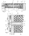
- a synthetic resin such an embodiment is shown in FIG. 3.
- the upper laminate layer 12o and the lower laminate layer 12o together form a torsion shell, in which the guide tube 13 is laid and the remaining space 14 is foamed.
- the end faces of the individual segments are flat and, as shown in FIG. 3, are likewise produced by end caps 15 from fiber-reinforced plastics which are glued to the torsion shell.
- Highly tear-resistant tensioning elements 16 run in the guide tubes 13 and are also made of fiber materials, for example; Of course, tensioning elements made of other materials, such as steel wires, steel cables or steel slats, are also possible.
- fiber materials are used for the tensioning elements, which are designed as loops. One end of the loop is attached to an adjusting element 17 on the lower tie rod 4. Threaded spindles, pulley elements or toggle levers etc. can be used as adjusting elements.
- a pull plate 19 which is adjustable by means of set screws 18 is used, which carries a bolt 20, around which the loop of the tensioning element 16 is placed. The set screws 18 are supported on the tie rod 4.
- the other end of the clamping elements 16 is placed around a retaining bolt 21 which is connected either to an end cap 15 of one of the blade sections 2 or, as shown in FIG. 3, to an intermediate flange 8.
- connecting bushes 22 are provided, through which the guide tubes 13 of two adjacent sheet sections are connected to one another. These connecting bushes are also guided through the intermediate flanges 8 if no clamping elements are fastened at this point, but are instead only guided to a next rotor blade section.
- the verb extension bushings 22 simultaneously secure the positive connection between the sheet sections 2 or this and the intermediate flanges; they also serve to transmit shear forces between individual blade sections and to absorb any torsional stresses on the blade during operation.
- the guide tubes could also be pulled out over the leaf section or the intermediate anchors and serve as a rotation lock.
- the individual rotor blade sections 2 are connected in the manner described by a large number of tensioning elements in the region of the pressure elements 9 of the sections, as is illustrated in FIG. 1 by the adjusting elements 17 indicated as adjusting screws.
- the individual sections without intermediate anchor 8 can only be clamped between the lower and upper tie rods 4 and 5. This results in homogeneous clamping forces across all leaf sections, which can only be influenced to a certain extent by the profile formation of these sections.
- the clamping force for individual sections can be adapted to the respective requirements.
- the natural frequency of the rotor blade which must be set to a characteristic value for proper operation, is also determined by additional tensioning elements.
- the construction of a rotor blade according to the invention provides the possibility of varying the natural frequency by correspondingly characteristic bracing of the individual sections of the rotor blade and thus adjusting it to the optimal value.
- the clamping force of the clamping elements must be greater than the maximum load on the rotor blade due to the centrifugal force and the bending.
- the adjusting elements 17 can be relieved after adjusting the clamping force for the clamping elements 16, for example by inserting wedges 23 under the tension plate 19, which absorb the clamping force, so that the set screws 18 are relieved in the tensioned state of the clamping elements 16.
- the guide tubes for the tension elements are located within the sandwich structure of the rotor blade.
- the guide tubes or guide channels for the tensioning elements in the inner chambers of the pressure elements 9, as is indicated schematically in FIG. 2 by the guide channels 13 ′ shown in dotted lines.
- the clamping elements can also be attached outside the blade contour in the aerodynamically non-disturbing area to increase the rigidity of the rotor blade; additional buoyancy can also be gained.
- cross section of the rotor blade does not have the same shape over the entire length of the blade as is shown in FIG. 2; like from
- FIG. 1 shows, the blade tapers towards the tip, the first sections 2 having a straight rear surface and only the sections in the outer region of the rotor blade having a blade flag, as shown in FIG. 2.
- the design of the rotor blades and the distribution of load-bearing pressure elements 9 and secondary parts that are not loaded in the pulling or pushing direction, such as blade flags or the like, depend on the requirements to be met of the rotor blade during operation. It is conceivable that the pressure element e.g. is formed only in one chamber and that the tie rods 4 and 5 cover only this area of the sheet.
- the rear part designated by 10 ' are not secondary parts that are subjected to tensile or compressive stress.
- the tie rods 4 and 5 and the intermediate anchor 8 extend over the entire sheet cross-section, adjustment elements 17 also being able to be provided on the tie rods in the region of the secondary parts 10 ', in which case, as mentioned above, the associated tensioning elements run outside the pressure elements 9'.
- the rotor blade tapers towards the blade tip.
- the guide tubes 13 for the tensioning elements 16 essentially follow the outer contour of the rotor blade and accordingly do not run in parallel, but instead form an overall slightly conical bundle. Accordingly, the clamping elements do not run in parallel, but take a certain angle against each other. This has the advantage that buckling forces acting on the rotor blade are also absorbed by the tensioning elements.
- the rotor blade described can be assembled and assembled directly at the installation site.
- the rotor head (not shown here) with tube 7, pipe socket 6 and tie rod 4 is first attached to the mast.
- the individual sheet sections 2 can then be pulled up over the tensioning elements 16 and, if necessary, tensioned with intermediate anchors 8.
- the bushings for the tensioning elements on the tie rod or on the leaf sections and the intermediate anchors, e.g. in the area of the connecting bushes 22, can be lined with a sliding layer made of polytetrafluoroethylene in order to reduce any frictional forces between the clamping elements and these bushings when pulling up.
Landscapes
- Engineering & Computer Science (AREA)
- Mechanical Engineering (AREA)
- Aviation & Aerospace Engineering (AREA)
- Life Sciences & Earth Sciences (AREA)
- Sustainable Development (AREA)
- Sustainable Energy (AREA)
- Chemical & Material Sciences (AREA)
- Combustion & Propulsion (AREA)
- General Engineering & Computer Science (AREA)
- Wind Motors (AREA)
Abstract
Description
- Bei aus einzelnen Abschnitten gefertigten Rotorblättern sind die einzelnen Abschnitte an einem Holm entweder einzeln befestigt oder auf den Holm aufgesteckt und dann insgesamt verspannt (vgl. DE-AS 14 06 443 bzw. FR-PS 888 216). Diese Rotorblätter sind für Hubschrauber konzipiert, wobei eine einfache Herstellung und hohe Elastizität der Rotorblätter angestrebt wird.
- In letzter Zeit wird erneut versucht, Strom mit Windkraftwerken zu erzeugen. Eine Möglichkeit besteht darin, an einem windreichen Ort einen hohen Mast aufzustellen, der einen Rotorflügel mit z.B. zwei Rotorblättern trägt; der vom Wind angetriebene Rotorflügel treibt dann einen Stromgenerator. Die Rotorblätter derartiger Flügel haben eine Länge von teilweise 60 Metern und wiegen dementsprechend je nach verwendetem Material bis zu 20 Tonnen. Für Rotorblätter mit diesen Ausmaßen können die bekannten Konstruktionsprinzipien nur bedingt übernommen werden, schon allein deshalb, da für Rotorflügel von Hubschraubern bzw. Windkraftwerken andere Bedingungen hinsichtlich der Elastizität bzw. Steifigkeit der Rotoren gegeben sind. Aufgrund der Größe der Rotorblätter für Windkraftwerke ergeben sich Probleme bei Herstellung, Montage und im Betrieb.
- Es ist vorgeschlagen worden, solche Rotorblätter einstückig aus faserverstärkten Kunststoffen herzustellen, da diese hinsichtlich Festigkeit und Gewicht Vorteile bieten. Zur Herstellung eines Rotorblattes wären demnach zumindest speziell anzufertigende Fertigungstische von etwa 60 Meter Länge sowie gleich lange Autoklaven notwend.ig, in denen die fertigen Rotorblätter bei Temperaturen zwischen 100 C und 2500C heißgehärtet werden.
- Auch der Transport und die Montage derartiger einstückiger Rotorblätter bzw. der Rotorflügel ist allein wegen der grossen Länge kompliziert. Da der Rotorflügel an dem Mast auch bei Wind montiert werden muß, müssen auch die Windkräfte durch entsprechende Montagehilfen beherrscht werden.
- Wird das eingangs erwähnte Konstruktionsprinzip von Hubschrauberrotorblättern aus einzelnen Abschnitten übernommen, so kann zwar die Fertigung dieser einzelnen Abschnitte erleichtert werden; die Montage der einzelnen Abschnitte auf dem im allgemeinen aus Stahlrohr hergestellten Blattholm, der Transport des fertigen Rotorblattes und auch dessen Montage an dem Mast verbleiben kompliziert.
- Im Betrieb schließlich ist ein Rotorflügel eines Windkraftwerkes extrem hohen Beanspruchungen ausgesetzt. So erreichen etwa die Blattspitzen des Rotors Geschwindigkeiten bis zu 150 Meter pro Sekunde; die auftretenden Zentrifugal- und auch Torsionskräfte müssen durch das Blattmaterial einwandfrei aufgefangen werden.
- Der Erfindung liegt die Aufgabe zugrunde, ein Rotorblatt so auszubilden, daß auch große Blätter einfach hergestellt und montiert werden können; außerdem sollen die Rotorblätter gute mechanische Eigenschaften aufweisen, so daß sie auch hohen Beanspruchungen Stand halten.
- Diese Aufgabe ist gemäß der Erfindung dadurch gelöst, daß die Abschnitte jeweils ein in Längsrichtung des Rotorblattes sich erstreckendes Druckelement in Form eines Holmabschnittes aufweisen, und daß die Druckelemente aller Abschnitte in Formschluß aneinandergefügt und durch verankerte und einstellbare, in Blattrichtung wirkende Spannelemente miteinander verspannt sind.
- Ein Rotorblatt gemäß der Erfindung unterscheidet sich von bekannten Konstruktionen einmal dadurch, daß auf einen selbstständigen Holm als eigenes Bauteil für das Rotorblatt verzichtet wird und zum anderen durch die Verbindung der einzelnen Blattabschnitte mittels Spannelementen, die zwischen Verstellelementen an einem Zuganker an der Blattwurzel und Befestigungspunkten an den jeweiligen zu verspannenden Blattabschnitten bzw. an diesen anliegenden Zwischen- oder Zugankern eingespannt sind. Die Abschnitte können hierbei in einfachster Weise alle gemeinsam zwischen dem Zuganker an der Blattwurzel und einem weiteren oberen Zuganker an der Blattspitze eingespannt werden. Zweckmäßigerweise wird jedoch eine Verspannung der Blattabschnitte einzeln etwa durch die erwähnten Zwischenanker gewählt; hierdurch kann die Spannkraft für jeden einzelnen Blattabschnitt individuell eingestellt werden. Mit der Einzelverspannung können unter anderem die Festigkeitseigenschaften des gesamten Blattes, aber auch die der einzelnen Abschnitte in gewissen Grenzen beeinflußt werden. Auf diese Weise kann das Rotorblatt optimal an die Anforderungen im Betrieb angepaßt werden. Von den erwähnten Festigkeitseigenschaften hängt z.B. auch die Eigenfrequenz des Rotorblattes ab, die für den einwandfreien Betrieb einen ganz bestimmten Wert einnehmen muß. Diese Eigenfrequenz kann bereits durch geringe Abweichungen in der Konstruktion des Blattes beeinflußt werden; außerdem ist es nicht immer ausgeschlossen, daß das fertige Rotorblatt eine geringfügig andere Eigenfrequenz als die berechnete aufweist. Bei einem Rotorblatt gemäß der Erfindung kann die Eigenfrequenz durch entsprechende Dimensionierung der Verspannung trotzdem noch auf den gewünschten Wert eingestellt werden, ohne daß das Rotorblatt oder zumindest ein Abschnitt neu konzipiert und gebaut werden müßte.
- Die Abschnitte des Rotorblattes gemäß der Erfindung können wegen der relativ kleinen Abmessungen in vorhandenen Fertigungsstätten hergestellt werden. Bei Blattgrößen von 6o Metern weisen die Blattabschnitte Längen zwischen etwa 6 und 12 Metern auf; Abschnitte solcher Längen können aus faserverstärkten Kunststoffen in bekannter Technologie hergestellt und auch in vorhandenen Autoklaven zur Verbesserung ihrer Festigkeitswerte heißgehärtet werden.
- Da das Rotorblatt nur auf Zug und Druck durch Verspannung und Zentrifugalkräfte sowie auf Torsion durch aerodynamische Beanspruchungen belastet wird, werden zweckmäßigerweise die Blattabschnitte als Sandwich-Konstruktionen aus einem Profilkern und darübergeschichteten Laminaten aus faserverstärkten Kunststoffen mit einheitlicher, in Zug- bzw. Druckrichtung liegender Faserrichtung ausgebildet. Selbstverständlich sind andere Konstruktionen mit anderen Materialien möglich, z.B. Harzkunststoffkonstruktionen mit billigen Füllstoffen wie etwa Asbestzement, Gas- oder Blähbetonkonstruktionen oder Metallkonstruktionen, soweit nur die Anforderungen an die Druckfestigkeit erfüllt werden. Der Profilkern kann etwa aus miteinander verbundenen Rechteckrohren aus Stahl oder auch aus faserverstärkten Kunststoffen bestehen. Der Kern kann ausgeschäumt werden. Auch die Ausbildung der Abschnitte in Form von ausgeschäumten Torsionsschalen ist möglich. Die Abschnitte brauchen nur über einen Teil ihres Querschnittes als Zug und Druck durch Verspannung und Zentrifugalkräfte aufnehmende Druckelemente ausgebildet sein, während die anderen Konturformen des Rotorblattes, z.B. die Blattfahnen als sekundäre, nicht tragende Teile ausgebildet werden. Derartige Konstruktionen sind bekannt und brauchen daher nicht näher erläutert zu werden.
- Im Kern der erwähnten Sandwich-Konstruktion können die Spannelemente verlaufen, die vorzugsweise in Führungsrohren angeordnet sind. Diese Führungsrohre werden bei der Herstellung der Blattabschnitte eingelegt bzw. in Schaum eingebettet. Ist die Wandstärke der Blattabschnitte nicht für eine solche Einbettung ausreichend, so werden die Führungsrohre in inneren Kammern des Rotorblattes verlegt. Die Führungsrohre benachbarter Blattabschnitte werden durch einsteckbare Verbindungsbuchsen untereinander verbunden, die gleichzeitig die Blattabschnitte gegen Verdrehen sichern.
- Ein Rotorblatt gemäß der Erfindung kann einfach hergestellt, transportiert und auch montiert werden. Beim Transport mnd der Montage ist es besonders vorteilhaft, daß hier nur mit Teilen überschaubarer Länge und damit auch noch handlichen Gewichtes gearbeitet werden kann.
- Weitere Ausgestaltungen und Vorteile der Erfindung gehen aus den Unteransprüchen und der nachfolgenden Beschreibung hervor, in der die Erfindung in einem Ausführungsbeispiel für ein Rotorblatt anhand der Zeichnung näher erläutert ist. In der Zeichnung stellen dar:
- Fig. 1 eine Ansicht eines Rotorblattes aus einzelnen Abschnitten gemäß der Erfindung;
- Fig. 2 einen Querschnitt durch das Rotorblatt;
- Fig. 3 einen Längsschnitt durch einen Teil eines Abschnittes des Rotorblattes und
- Fig. 4 einen Teilquerschnitt durch einen Zuganker mit verspanntem Blattabschnitt für ein Rotorblatt gemäß der Erfindung.
- In Fig. 1 ist ein Rotorblatt 1 dargestellt, das aus mehreren Abschnitten 2 zusammengesetzt ist. An der Blattspitze ist ein Abschlußelement 3 vorgesehen. Die Abschnitte 2 sind durch einen unteren Zuganker 4 an der Blattivurzel und einen Zuganker 5 an der Blattspitze eingespannt. Am unteren Zuganker 4 ist ein Rohrstutzen 6 befestigt, in dem ein weiteres Rohr 7 gelagert ist, das mit einem hier nicht gezeigten Rotorkopf verbunden ist und über das der Anstellwinkel des Rotorblattes eingestellt werden kann. Die einzelnen Abschnitte des Rotorblattes stoßen entweder direkt aneinander an, wie dies in dem aufgebrochenen Bereich des Rotorblattes in Figur 1 dargestellt ist, oder es sind jeweils zwischen zwei Abschnitten Zwischenanker 7 vorgesehen. Die Verbindung zwischen den Abschnitten bzw. zwischen diesen und den Zwischenankern beruhen auf Formschluß. Die Abschnitte des Rotorblattes sind zwischen den Zugankern 4 und 5 bzw. den Zwischenankern 7 verspannt, wie dies noch erläutert wird.
- Die Abschnitte 2 des Rotorblattes sind im wesentlichen sogenannte Sandwich-Konstruktionen, wie dieses schematisch in Fig. 2 dargestellt ist. Der Abschnitt 2 des Rotorblattes weist ein zweikammriges Druckelement 9 auf, an das die Blattfahne 1o geklebt ist. Das Druckelement 9 besteht aus aneinandergefügten und miteinander verklebten Stützkernen 11, die mit Laminaten 12 aus faserverstärktem Kunststoff armiert werden; eine solche Technik ist bekannt und braucht hier nicht näher erläutert zu werden. In den Stützkernen 11 sind Führungsrohre 13 verlegt, wonach der Restraum in den Stützkernen z.B. ausgeschäumt wird. Die Stützkerne 11 können entweder Profile aus faserverstärkten Kunststoffen mit unidirektionaler Faserrichtung sein; es sind aber auch Metallprofile und Ähnliches denkbar. Anstelle der Stützkerne kann auch der Raum zwischen den Laminaten 12 mit einem Kunstharz ausgefüllt werden, wobei dann die Führungsrohre 13 direkt in dem Kunstharz verlegt sind. Eine solche Ausgestaltung ist in Fig. 3 dargestellt. Hier bilden die obere Laminatschicht 12o und die untere Laminatschicht 12o zusammen eine Torsionsschale, in der das Führungsrohr 13 verlegt ist und deren Restraum 14 ausgeschäumt ist. Die Abschlußflächen der einzelnen Segmente sind eben und werden, wie dies in Figur 3 gezeigt ist, durch Endkappen 15 ebenfalls aus faserverstärkten Kunststoffen hergestellt, die mit der Torsionsschale verklebt sind.
- In den Führungsrohren 13 laufen hochreißfeste Spannelemente 16, die z.B. ebenfalls aus Faserwerkstoffen ausgebildet sind; selbstverständlich sind auch Spannelemente aus anderen Materialien, so z.B. Stahldrähte, Stahlseile oder Stahllamellen möglich. In dem hier dargestellten Ausführungsbeispiel sind Faserwerkstoffe für die Spannelemente verwendet, die als Schlaufen ausgebildet sind. Das eine Ende der Schlaufe ist am unteren Zuganker 4 an einem Verstellelement 17 befestigt. Als Verstellelemente können Gewindespindeln, Flaschenzugelemente oder Kniehebel etc. verwendet werden. Bei dem Ausführungsbeispiel gemäß Figur 4 wird eine über Stellschrauben 18 verstellbare Zugplatte 19 verwendet, die einen Bolzen 2o trägt, um den die Schlaufe des Spannelementes 16 gelegt ist. Die Stellschrauben 18 stützen sich auf den Zuganker 4 ab. Das andere Ende der Spannelemente 16 ist um einen Haltebolzen 21 gelegt, der entweder mit einer Endkappe 15 eines der Blattabschnitte 2 oder, wie in Figur 3 dargestellt, mit einem Zwischenflansch 8 verbunden ist. An den Stoßstellen zwischen den einzelnen Blattabschnitten 2 bzw. diesen und etwaigen Zwischenflanschen sind jeweils Verbindungsbuchsen 22 vorgesehen, durch die die Führungsrohre 13 zweier benachbarter Blattabschnitte miteinander verbund.en werden. Diese Verbindungsbuchsen werden auch durch die Zwischenflansche 8 geführt, wenn an dieser Stelle keine Spannelemente befestigt, sondern lediglich zu einem nächsten Rotorblattabschnitt geführt werden. Die Verbindungsbuchsen 22 sichern gleichzeitig den Formschluß zwischen den Blattabschnitten 2 bzw. diesen und den Zwischenflanschen; sie dienen ferner dazu, zwischen einzelnen Blattabschnitten Schubkräfte zu übertragen und etwaige Torsionsbeanspruchungen des Blattes im Betrieb aufzunehmen. Anstelle der Verbindungsbuchsen 22 könnten auch die Führungsrohre über d.en Blattabschnitt bzw. die Zwischenanker herausgezogen werden und als Drehsicherung dienen.
- Hierfür könnten selbstverständlich auch andere Konstruktionen dienen; z.B. könnten die Stirnflächen der Rotorblattabschnitte und der Zwischenflansche verzahnt werden; dies bedingt allerdings einen höheren Fertigungsaufwand.
- Die einzelnen Rotorblattabschnitte 2 werden auf die geschilderte Weise durch eine Vielzahl von Spannelementen im Bereich der Druckelemente 9 der Abschnitte verbunden, wie dies in Fig. 1 durch die als Stellschrauben angedeuteten Verstellelemente 17 verdeutlicht wird.
- Je nach den Anforderungen an die Steifigkeit und andere Eigenschaften des Rotorblattes können die einzelnen Abschnitte ohne Zwischenanker 8 lediglich zwischen dem unteren und oberen Zuganker 4 bzw. 5 eingespannt werden. Hier ergeben sich homogene Spannkräfte über alle Blattabschnitte, die lediglich durch die Profilausbildung dieser Abschnitte in gewissem Rahmen beeinflußt werden können. Wenn Zwischenanker 8 vorgesehen werden, ist die Spannkraft für einzelne Abschnitte an die jeweiligen Anforderungen anpaßbar. Zum Beispiel wird durch zusätzliche Spannelemente auch die Eigenfrequenz des Rotorblattes bestimmt, die für einen einwandfreien Betrieb auf einen charakteristischen Wert eingestellt werden muß. Bei der Konstruktion eines Rotorblattes gemäß der Erfindung ist die Möglichkeit gegeben, durch entsprechende charakteristische Verspannung der einzelnen Abschnitte des Rotorblattes die Eigenfrequenz zu variieren und damit auf den optimalen Wert einzustellen. Durch die Einzelverspannung der Abschnitte können auch andere charakteristische Werte, so z.B. die Festigkeit des Blattes in bestimmten Bereichen variiert und optimal an die Verhältnisse angepaßt werden. Auf jeden Fall muß die Spannkraft der Spannelemente größer als die maximale Belastung des Rotorblattes aufgrund der Fliehkraft und der Biegung sein. Die Verstellelemente 17 können nach Einstellen der Spannkraft für die Spannelemente 16 entlastet werden, indem z.B. unter die Zugplatte 19 Keile 23 eingeführt werden, die die Spannkraft aufnehmen, so daß die Stellschrauben 18 im gespannten Zustand der Spannelemente 16 entlastet sind.
- Bei dem dargestellten Ausführungsbeispiel sind die Führungsrohre für die Zugelemente innerhalb der Sandwich-Struktur des Rotorblattes gelegen. Bei kleineren Rotorblättern mit dünnen Wandstärken ist es ebenfalls möglich, die Führungsrohre bzw. Führungskanäle für die Spannelemente in die Innenkammern der Druckelemente 9 zu legen, wie dieses schematisch in Figur 2 durch die gepunktet gezeichneten Führungskanäle 13' angedeutet ist. In besonders gelagerten Fällen können auch zur Erhöhung der Steifigkeit des Rotorblattes die Spannelemente außerhalb der Blattkontur in aerodynamisch nicht störenden Bereich angebracht werden; es kann hierbei auch zusätzlich Auftrieb gewonnen werden.
- Es sei noch darauf hingewiesen, daß der Querschnitt des Rotorblattes nicht über die gesamte Länge des Blattes die gleiche Form aufweist, wie sie in Figur 2 dargestellt ist; wie aus
- Figur 1 hervorgeht, verjüngt sich das Blatt zur Spitze hin, wobei die ersten Abschnitte 2 eine gerade Rückfläche und erst die Abschnitte im äußeren Bereich des Rotorblattes eine Blattfahne, wie in Figur 2 dargestellt, aufweisen. Die Ausbildung der Rotorblätter und die Verteilung von tragenden Druckelementen 9 und nicht in Zug- bzw. Druckrichtung belasteten Sekundärteilen, wie Blattfahnen oder ähnlichem hängt von den zu erfüllenden Anforderungen an das Rotorblatt im Betrieb ab. So ist es denkbar, daß das Druckelement z.B. lediglich einkammerig ausgebildet ist und daß auch die Zuganker 4 und 5 nur diesen Bereich des Blattes abdecken. In Figur 1 ist mit 9' der vordere Teil des Rotorblattes bezeichnet, der als Druckelement ausgeführt ist. Der rückwärtige mit 10' bezeichnete Teil sind nicht auf Zug- oder Druck beanspruchte Sekundärteile. Die Zuganker 4 und 5 und die Zwischenanker 8 erstrecken sich über den gesamten Blattquerschnitt, wobei auch im Bereich der Sekundärteile 10' an den Zugankern Verstellelemente 17 vorgesehen sein können, wobei dann, wie oben erwähnt, die zugeordneten Spannelemente außerhalb der Druckelemente 9' verlaufen.
- Das Rotorblatt verjüngt sich, wie bereits erwähnt, zur Blattspitze hin. Die Führungsrohre 13 für die Spannelemente 16 folgen im wesentlichen der Außenkontur des Rotorblattes und laufen demnach nicht parallel, sondern bilden insgesamt ein leicht konisch verlaufendes Bündel. Dementsprechend laufen auch die Spannelemente nicht parallel, sondern nehmen gegeneinander einen gewissen Winkel ein. Dies hat den Vorteil, daß durch die Spannelemente auch auf das Rotorblatt wirkende Knickkräfte aufgenommen werden.
- Das beschriebene Rotorblatt kann direkt am Aufstellungsort zusammengesetzt und montiert werden. Hierzu wird zunächst am Mast der hier nicht gezeigte Rotorkopf mit Rohr 7, Rohrstutzen 6 und Zuganker 4 befestigt. Die einzelnen Blattabschnitte 2 können dann über die Spannelemente 16 hochgezogen, und wenn notwendig, mit Zwischenankern 8 verspannt werden. Die Durchführungen für die Spannelemente am Zuganker bzw. an den Blattabschnitten und den Zwischenankern, z.B. im Bereich der Verbindungsbuchsen 22, können mit einer Gleitschicht aus Polytetrafluoräthylen ausgekleidet sein, um so etwaige Reibungskräfte zwischen den Spannelementen und diesen Durchführungen beim Hochziehen zu verringern.
- Auch Rotorblätter großer Ausmaße können, wenn sie gemäß der Erfindung ausgebildet werden, in bereits vorhandenen Fertigungseinrichtungen hergestellt und mit einem relativ geringen Aufwand zusammengesetzt bzw. montiert werden.
Claims (21)
Applications Claiming Priority (2)
| Application Number | Priority Date | Filing Date | Title |
|---|---|---|---|
| DE2921152 | 1979-05-25 | ||
| DE2921152A DE2921152C2 (de) | 1979-05-25 | 1979-05-25 | Rotorblatt für Windkraftwerke |
Publications (2)
| Publication Number | Publication Date |
|---|---|
| EP0019691A1 true EP0019691A1 (de) | 1980-12-10 |
| EP0019691B1 EP0019691B1 (de) | 1983-05-18 |
Family
ID=6071630
Family Applications (1)
| Application Number | Title | Priority Date | Filing Date |
|---|---|---|---|
| EP80101431A Expired EP0019691B1 (de) | 1979-05-25 | 1980-03-19 | Aus einzelnen Abschnitten gefertigtes Rotorblatt |
Country Status (5)
| Country | Link |
|---|---|
| US (1) | US4389162A (de) |
| EP (1) | EP0019691B1 (de) |
| JP (1) | JPS55156797A (de) |
| DE (1) | DE2921152C2 (de) |
| DK (1) | DK225980A (de) |
Cited By (12)
| Publication number | Priority date | Publication date | Assignee | Title |
|---|---|---|---|---|
| EP0062737A1 (de) * | 1981-04-10 | 1982-10-20 | Messerschmitt-Bölkow-Blohm Gesellschaft mit beschränkter Haftung | Rotorblatt oder- Bauteil und Verfahren zu dessen Herstellung |
| EP0061567A3 (en) * | 1981-04-01 | 1984-09-26 | Messerschmitt-Bolkow-Blohm Gesellschaft Mit Beschrankter Haftung | Aerodynamic propeller blade and manufacturing process |
| NL1001200C2 (nl) * | 1995-09-15 | 1997-03-20 | Aerpac Special Products B V | Molenwiek. |
| WO2009034292A3 (en) * | 2007-09-11 | 2009-09-03 | Blade Dynamics Limited | A root end joint for a wind turbine blade |
| EP1561947A3 (de) * | 2004-02-05 | 2010-10-27 | Fuji Jukogyo Kabushiki Kaisha | Windturbinenschaufel in Absschnitten transportfähig |
| CN101571101B (zh) * | 2008-04-30 | 2012-03-07 | 北京航空航天大学 | 一种分列式水平轴风电叶片 |
| EP2031245A3 (de) * | 2007-09-03 | 2013-01-02 | Daubner & Stommel GbR Bau-Werk-Planung | Rotorblatt sowie Windenergieanlage |
| EP2419624A4 (de) * | 2009-04-13 | 2014-04-16 | Maxiflow Mfg Inc | Windturbinenblatt und konstruktionsverfahren dafür |
| EP2434144A3 (de) * | 2010-09-22 | 2014-05-14 | Nordex Energy GmbH | Rotorblatt oder Rotorblattsegment für eine Windenergieanlage |
| EP2434143A3 (de) * | 2010-09-22 | 2014-05-21 | Nordex Energy GmbH | Rotorblatt oder Rotorblattsegment für eine Windenergieanlage |
| CN115384765A (zh) * | 2022-10-31 | 2022-11-25 | 四川蓉远地测科技有限公司 | 旋翼无人机驱动装置及其装配方法 |
| DE102023003837A1 (de) | 2023-09-12 | 2025-03-13 | Gerold Bernhardt | Teilbares Rotorblatt für eine Windkraftanlage in Hybridbauweise ohne Carbon sowie Vorrichtung für Auswuchtanlage |
Families Citing this family (51)
| Publication number | Priority date | Publication date | Assignee | Title |
|---|---|---|---|---|
| US4557666A (en) * | 1983-09-29 | 1985-12-10 | The Boeing Company | Wind turbine rotor |
| US4565929A (en) * | 1983-09-29 | 1986-01-21 | The Boeing Company | Wind powered system for generating electricity |
| US5269657A (en) * | 1990-07-20 | 1993-12-14 | Marvin Garfinkle | Aerodynamically-stable airfoil spar |
| DE4447942B4 (de) * | 1994-10-11 | 2016-10-20 | Aloys Wobben | Windenergieanlage mit Blitzschutzeinrichtung |
| DE19962989B4 (de) | 1999-12-24 | 2006-04-13 | Wobben, Aloys, Dipl.-Ing. | Rotorblatt für Windenergieanlagen |
| RU2301911C2 (ru) * | 2001-07-11 | 2007-06-27 | Хюдра Тидаль Энерджи Текнолоджи Ас | Электростанция, генератор и элемент пропеллера для получения энергии с использованием потока воды |
| ES2574779T5 (es) * | 2001-07-19 | 2022-02-17 | Vestas Wind Sys As | Alabe para aerogenerador |
| DE10235496B4 (de) * | 2002-08-02 | 2015-07-30 | General Electric Co. | Verfahren zum Herstellen eines Rotorblattes, Rotorblatt und Windenergieanlage |
| US7118338B2 (en) * | 2004-06-30 | 2006-10-10 | General Electric Company | Methods and apparatus for twist bend coupled (TCB) wind turbine blades |
| GB0415545D0 (en) | 2004-07-12 | 2004-08-11 | Peace Steven | Wind turbine |
| ES2265760B1 (es) * | 2005-03-31 | 2008-01-16 | GAMESA INNOVATION & TECHNOLOGY, S.L. | Pala para generadores eolicos. |
| US7393184B2 (en) * | 2005-11-10 | 2008-07-01 | General Electric Company | Modular blades and methods for making same |
| US7798780B2 (en) * | 2005-12-19 | 2010-09-21 | General Electric Company | Modularly constructed rotorblade and method for construction |
| US7517198B2 (en) * | 2006-03-20 | 2009-04-14 | Modular Wind Energy, Inc. | Lightweight composite truss wind turbine blade |
| US7654799B2 (en) | 2006-04-30 | 2010-02-02 | General Electric Company | Modular rotor blade for a wind turbine and method for assembling same |
| DE102006022279B4 (de) * | 2006-05-11 | 2016-05-12 | Aloys Wobben | Rotorblatt für eine Windenergieanlage |
| DE102007036917A1 (de) | 2007-08-06 | 2009-02-12 | Hafner, Edzard, Prof. Dr.-Ing. | Rotorblatt für Windkraftanlagen, insbesondere für schwimmende Windkraftanlagen, sowie Windkraftanlage mit einem Rotorblatt |
| US20090070977A1 (en) * | 2007-09-13 | 2009-03-19 | General Electric Company | Jig And Fixture For Wind Turbine Blade |
| US8123488B2 (en) | 2007-09-17 | 2012-02-28 | General Electric Company | System and method for joining turbine blades |
| US8733549B2 (en) | 2007-11-13 | 2014-05-27 | General Electric Company | System for containing and/or transporting wind turbine components |
| US8510947B2 (en) * | 2008-11-14 | 2013-08-20 | General Electric Company | Turbine blade fabrication |
| DK2358998T3 (en) | 2008-12-05 | 2017-10-30 | Vestas Wind Sys As | EFFICIENT WINDOWS, WINDOWS, AND ASSOCIATED SYSTEMS AND PROCEDURES FOR MANUFACTURING, INSTALLING AND USING |
| US7891947B2 (en) * | 2008-12-12 | 2011-02-22 | General Electric Company | Turbine blade and method of fabricating the same |
| GB2467745A (en) * | 2009-02-11 | 2010-08-18 | Vestas Wind Sys As | Wind turbine blade with tension element(s) to increase edgewise stiffness |
| DE102009023001A1 (de) * | 2009-05-28 | 2010-12-02 | Smart Blade Gmbh | Modulares Rotorblatt für eine Windkraftanlage |
| DE102009040515A1 (de) | 2009-09-03 | 2011-03-10 | Grimm, Friedrich, Prof. Dipl.-Ing. | Rotorblatt für eine Windturbine mit horizontaler Rotationsachse |
| DE102009046586B4 (de) * | 2009-11-10 | 2012-02-23 | Nordex Energy Gmbh | Blattspitze für ein Rotorblatt einer Windenergieanlage und Verfahren zur Montage der Blattspitze an ein Rotorblatt |
| US20110123343A1 (en) * | 2009-11-24 | 2011-05-26 | Ronner David E | Wind turbine blade and methods, apparatus and materials for fabrication in the field |
| US20100135796A1 (en) * | 2009-12-01 | 2010-06-03 | Venkateswara Rao Kavala | Monitoring joint efficiency in wind turbine rotor blades |
| US10137542B2 (en) | 2010-01-14 | 2018-11-27 | Senvion Gmbh | Wind turbine rotor blade components and machine for making same |
| BR112012017122B1 (pt) | 2010-01-14 | 2021-09-28 | Senvion Gmbh | Feixe compósito para uma pá de turbina eólica |
| CA2690955A1 (en) * | 2010-01-28 | 2011-07-28 | Olivier Blanc | Wind turbine structure and method of assembly |
| WO2011098084A1 (en) * | 2010-02-12 | 2011-08-18 | Thomas Holding Århus A/S | Foam members and a spar are assembled then coated and finished to form a blade for a wind turbine |
| US9500179B2 (en) | 2010-05-24 | 2016-11-22 | Vestas Wind Systems A/S | Segmented wind turbine blades with truss connection regions, and associated systems and methods |
| US8172539B2 (en) * | 2010-06-17 | 2012-05-08 | General Electric Company | Wind turbine rotor blade joint |
| CA2809185A1 (en) * | 2010-08-24 | 2012-03-01 | Siemens Aktiengesellschaft | Formation of a core structure of a wind turbine rotor blade by using a plurality of basic core components |
| DE102010039778B4 (de) | 2010-08-25 | 2018-03-01 | Skywind Gmbh | Rotorblatt für Windenergieanlagen |
| US20110243736A1 (en) * | 2010-12-08 | 2011-10-06 | General Electric Company | Joint sleeve for a rotor blade assembly of a wind turbine |
| US20110206510A1 (en) * | 2010-12-20 | 2011-08-25 | Reinhard Langen | Modular rotor blade and method for mounting a wind turbine |
| US20130309095A1 (en) * | 2012-05-17 | 2013-11-21 | SkyWolf Wind Turbine Corp. | Wind turbine blade having improved structural and aerodynamic characteristics |
| US9605650B2 (en) | 2012-12-04 | 2017-03-28 | General Electric Company | Wind blades with mechanical elements for pretensioning in tension fabrics |
| DE102015117437A1 (de) * | 2015-10-14 | 2017-04-20 | Wobben Properties Gmbh | Windenergieanlagen-Rotorblatt und Verfahren zum Herstellen eines Windenergieanlagen-Rotorblattes |
| US10495058B2 (en) * | 2017-02-21 | 2019-12-03 | General Electric Company | Joint assembly for rotor blade segments of a wind turbine |
| US10961982B2 (en) | 2017-11-07 | 2021-03-30 | General Electric Company | Method of joining blade sections using thermoplastics |
| DE102018108695A1 (de) | 2018-04-12 | 2019-10-17 | Wobben Properties Gmbh | Windenergieanlagen-Rotorblatt und Windenergieanlage |
| DE102018108906A1 (de) | 2018-04-16 | 2019-10-17 | Wobben Properties Gmbh | Windenergieanlagen-Rotorblatt und Windenergieanlage |
| US11353002B2 (en) | 2019-01-16 | 2022-06-07 | Roller Bearing Company Of America, Inc. | Multi segment wind turbine blade joint bushing |
| GB202020710D0 (en) | 2020-12-30 | 2021-02-10 | Gen Electric | Method of joining segments of a composite component |
| DE102022104017A1 (de) * | 2022-02-21 | 2023-08-24 | Wobben Properties Gmbh | Rotorblatt einer Windenergieanlage |
| DE102023100609A1 (de) * | 2023-01-12 | 2024-07-18 | Nordex Energy Se & Co. Kg | Geteiltes Windenergieanlagenrotorblatt sowie Verfahren zum Verbinden zweier Rotorblattsegmente eines Windenergieanlagenrotorblatts |
| DE102024116974A1 (de) * | 2024-06-17 | 2025-12-18 | Deutsches Zentrum für Luft- und Raumfahrt e.V. | Windkraftanlage |
Citations (3)
| Publication number | Priority date | Publication date | Assignee | Title |
|---|---|---|---|---|
| NL14424C (de) * | ||||
| FR888216A (fr) * | 1942-02-03 | 1943-12-07 | Sncase | Procédé de montage et de fixation des éléments constituant des pales sustentatrices pour voilure tournante par utilisation d'un longeron profilé |
| DE943880C (de) * | 1952-02-29 | 1956-06-01 | Karl Wolf Dipl Ing | Windradfluegel |
Family Cites Families (9)
| Publication number | Priority date | Publication date | Assignee | Title |
|---|---|---|---|---|
| US2734586A (en) * | 1956-02-14 | Low-density propeller blade | ||
| US1785318A (en) * | 1929-01-26 | 1930-12-16 | Dfan Mcg Gilfillan | Wing structure for airplanes |
| US1879225A (en) * | 1929-06-28 | 1932-09-27 | Firm Of Propeller Ag | Propeller blade |
| US2254821A (en) * | 1938-01-07 | 1941-09-02 | Haw Jakob Heinrich | Airscrew blade construction |
| US2869649A (en) * | 1953-04-07 | 1959-01-20 | Murdo Mackenzie | Helicopter rotor |
| FR1187166A (fr) * | 1957-11-14 | 1959-09-08 | Perfectionnements apportés aux machines à pales, notamment aux éoliennes | |
| US3108640A (en) * | 1961-04-18 | 1963-10-29 | Daimler Benz Ag | Structural connection between rotatable parts |
| GB1290134A (de) * | 1970-01-23 | 1972-09-20 | ||
| IT1091214B (it) * | 1977-12-05 | 1985-07-06 | Fiat Spa | Pala per motori eolici |
-
1979
- 1979-05-25 DE DE2921152A patent/DE2921152C2/de not_active Expired
-
1980
- 1980-03-19 EP EP80101431A patent/EP0019691B1/de not_active Expired
- 1980-05-13 US US06/149,523 patent/US4389162A/en not_active Expired - Lifetime
- 1980-05-23 JP JP6879780A patent/JPS55156797A/ja active Pending
- 1980-05-23 DK DK225980A patent/DK225980A/da not_active Application Discontinuation
Patent Citations (3)
| Publication number | Priority date | Publication date | Assignee | Title |
|---|---|---|---|---|
| NL14424C (de) * | ||||
| FR888216A (fr) * | 1942-02-03 | 1943-12-07 | Sncase | Procédé de montage et de fixation des éléments constituant des pales sustentatrices pour voilure tournante par utilisation d'un longeron profilé |
| DE943880C (de) * | 1952-02-29 | 1956-06-01 | Karl Wolf Dipl Ing | Windradfluegel |
Cited By (15)
| Publication number | Priority date | Publication date | Assignee | Title |
|---|---|---|---|---|
| EP0061567A3 (en) * | 1981-04-01 | 1984-09-26 | Messerschmitt-Bolkow-Blohm Gesellschaft Mit Beschrankter Haftung | Aerodynamic propeller blade and manufacturing process |
| EP0062737A1 (de) * | 1981-04-10 | 1982-10-20 | Messerschmitt-Bölkow-Blohm Gesellschaft mit beschränkter Haftung | Rotorblatt oder- Bauteil und Verfahren zu dessen Herstellung |
| NL1001200C2 (nl) * | 1995-09-15 | 1997-03-20 | Aerpac Special Products B V | Molenwiek. |
| EP1561947A3 (de) * | 2004-02-05 | 2010-10-27 | Fuji Jukogyo Kabushiki Kaisha | Windturbinenschaufel in Absschnitten transportfähig |
| EP2031245A3 (de) * | 2007-09-03 | 2013-01-02 | Daubner & Stommel GbR Bau-Werk-Planung | Rotorblatt sowie Windenergieanlage |
| WO2009034292A3 (en) * | 2007-09-11 | 2009-09-03 | Blade Dynamics Limited | A root end joint for a wind turbine blade |
| US8425195B2 (en) | 2007-09-11 | 2013-04-23 | Blade Dynamics Limited | Wind turbine blade |
| CN101571101B (zh) * | 2008-04-30 | 2012-03-07 | 北京航空航天大学 | 一种分列式水平轴风电叶片 |
| EP2419624A4 (de) * | 2009-04-13 | 2014-04-16 | Maxiflow Mfg Inc | Windturbinenblatt und konstruktionsverfahren dafür |
| EP3070326A1 (de) * | 2009-04-13 | 2016-09-21 | Maxiflow Manufacturing Inc. | Windturbinenblatt und konstruktionsverfahren dafür |
| EP2434144A3 (de) * | 2010-09-22 | 2014-05-14 | Nordex Energy GmbH | Rotorblatt oder Rotorblattsegment für eine Windenergieanlage |
| EP2434143A3 (de) * | 2010-09-22 | 2014-05-21 | Nordex Energy GmbH | Rotorblatt oder Rotorblattsegment für eine Windenergieanlage |
| CN115384765A (zh) * | 2022-10-31 | 2022-11-25 | 四川蓉远地测科技有限公司 | 旋翼无人机驱动装置及其装配方法 |
| CN115384765B (zh) * | 2022-10-31 | 2023-03-24 | 四川蓉远地测科技有限公司 | 旋翼无人机驱动装置及其装配方法 |
| DE102023003837A1 (de) | 2023-09-12 | 2025-03-13 | Gerold Bernhardt | Teilbares Rotorblatt für eine Windkraftanlage in Hybridbauweise ohne Carbon sowie Vorrichtung für Auswuchtanlage |
Also Published As
| Publication number | Publication date |
|---|---|
| DE2921152C2 (de) | 1982-04-22 |
| DK225980A (da) | 1980-11-26 |
| DE2921152A1 (de) | 1980-11-27 |
| EP0019691B1 (de) | 1983-05-18 |
| US4389162A (en) | 1983-06-21 |
| JPS55156797A (en) | 1980-12-06 |
Similar Documents
| Publication | Publication Date | Title |
|---|---|---|
| EP0019691B1 (de) | Aus einzelnen Abschnitten gefertigtes Rotorblatt | |
| EP1000243B1 (de) | Anschluss des rotorblatts einer windenergieanlage an eine rotornabe | |
| EP0057272B1 (de) | Rotorblatt in Schalenbauweise | |
| EP1244873B1 (de) | Verwendung einer stossverbindung für rotorblätter | |
| EP2731772B1 (de) | Verfahren zum herstellen eines rotorblatts für eine windenergieanlage | |
| EP1914383B1 (de) | Fanschaufel aus Textilverbundwerkstoff | |
| DE60203804T3 (de) | Windturbinenblatt | |
| EP2363599B1 (de) | Rotorblatt für eine Windenergieanlage, Windenergieanlage und Verfahren zum Herstellen eines Rotorblatts | |
| DE20320714U1 (de) | Rotorblatt für Windenergieanlagen | |
| DE3021929A1 (de) | Holmanordnung fuer einen sich verjuengenden fluegel einer windenergieanlage | |
| DE2942519A1 (de) | Gabelkopf zur befestigung von rotorblaettern an einem hubschrauber-rotormast | |
| EP3496936A1 (de) | Gurt aus vorgefertigten elementen mit gelege und ein verfahren zu seiner fertigung | |
| DE102007036917A1 (de) | Rotorblatt für Windkraftanlagen, insbesondere für schwimmende Windkraftanlagen, sowie Windkraftanlage mit einem Rotorblatt | |
| DE102012209935A1 (de) | Hinterkasten, Rotorblatt mit Hinterkasten und Windenergieanlage mit solchem Rotorblatt | |
| DE2645174C2 (de) | Rotorkopf für einen schlag- und schwenkgelenklosen Rotor | |
| DE102011017460A1 (de) | Faserverbundbauteil, Flügelspitzenverlängerung und Flugzeug mit einem Faserverbundteil | |
| EP3752732B1 (de) | Verfahren zur herstellung eines geteilten rotorblatts und rotorblatt | |
| DE202013007886U1 (de) | Windenergieanlagenrotorblatt mit passiver Lastreduzierung | |
| EP3551438B1 (de) | Hinterkantengurt eines rotorblatts einer windenergieanlage, rotorblatt und verfahren zum herstellen eines hinterkantengurts | |
| DE102017126276A1 (de) | Verfahren zur Herstellung einer Steg-Gurt-Baugruppe für ein Windenergieanlagenrotorblatt und Steg-Gurt-Baugruppe | |
| EP3564523B1 (de) | Flanschanschluss für ein windenergieanlagenrotorblatt, versteifungslage für einen flanschanschluss, flanscheinleger, windenergieanlagenrotorblatt, windenergieanlage sowie verfahren zum herstellen eines flanschanschlusses | |
| EP3845354A2 (de) | Verfahren zum herstellen von segmenten für einen turm, vorgespanntes segment, turmring, turm, windenergieanlage sowie vorspannvorrichtung | |
| DE102005047961A1 (de) | Hybridturm | |
| EP3887670A1 (de) | Verfahren zum einbringen eines rotorblattgurts in eine rotorblattschale, gurtform, rotorblatt sowie windenergieanlage | |
| DE102016014908A1 (de) | Rotorblatt, Windenergieanlage mit einem Rotorblatt und Reparatursatz und Verfahren zum Verstärken eines Rotorblatts |
Legal Events
| Date | Code | Title | Description |
|---|---|---|---|
| PUAI | Public reference made under article 153(3) epc to a published international application that has entered the european phase |
Free format text: ORIGINAL CODE: 0009012 |
|
| AK | Designated contracting states |
Designated state(s): FR GB NL SE |
|
| 17P | Request for examination filed |
Effective date: 19810223 |
|
| GRAA | (expected) grant |
Free format text: ORIGINAL CODE: 0009210 |
|
| AK | Designated contracting states |
Designated state(s): FR GB NL SE |
|
| ET | Fr: translation filed | ||
| PG25 | Lapsed in a contracting state [announced via postgrant information from national office to epo] |
Ref country code: SE Effective date: 19840320 |
|
| PGFP | Annual fee paid to national office [announced via postgrant information from national office to epo] |
Ref country code: NL Payment date: 19840331 Year of fee payment: 5 |
|
| PLBE | No opposition filed within time limit |
Free format text: ORIGINAL CODE: 0009261 |
|
| PLBE | No opposition filed within time limit |
Free format text: ORIGINAL CODE: 0009261 |
|
| STAA | Information on the status of an ep patent application or granted ep patent |
Free format text: STATUS: NO OPPOSITION FILED WITHIN TIME LIMIT |
|
| 26N | No opposition filed | ||
| 26N | No opposition filed | ||
| GBPC | Gb: european patent ceased through non-payment of renewal fee | ||
| GBPC | Gb: european patent ceased through non-payment of renewal fee | ||
| PG25 | Lapsed in a contracting state [announced via postgrant information from national office to epo] |
Ref country code: FR Free format text: LAPSE BECAUSE OF NON-PAYMENT OF DUE FEES Effective date: 19841130 |
|
| REG | Reference to a national code |
Ref country code: FR Ref legal event code: ST |
|
| PG25 | Lapsed in a contracting state [announced via postgrant information from national office to epo] |
Ref country code: NL Effective date: 19851001 |
|
| NLV4 | Nl: lapsed or anulled due to non-payment of the annual fee | ||
| PG25 | Lapsed in a contracting state [announced via postgrant information from national office to epo] |
Ref country code: GB Effective date: 19881118 |
|
| EUG | Se: european patent has lapsed |
Ref document number: 80101431.7 Effective date: 19850529 |