EP0019694A2 - Processor controlled printing device and operation thereof - Google Patents
Processor controlled printing device and operation thereof Download PDFInfo
- Publication number
- EP0019694A2 EP0019694A2 EP80101466A EP80101466A EP0019694A2 EP 0019694 A2 EP0019694 A2 EP 0019694A2 EP 80101466 A EP80101466 A EP 80101466A EP 80101466 A EP80101466 A EP 80101466A EP 0019694 A2 EP0019694 A2 EP 0019694A2
- Authority
- EP
- European Patent Office
- Prior art keywords
- drum
- printing
- critical
- paper
- during
- Prior art date
- Legal status (The legal status is an assumption and is not a legal conclusion. Google has not performed a legal analysis and makes no representation as to the accuracy of the status listed.)
- Granted
Links
Images


Classifications
-
- B—PERFORMING OPERATIONS; TRANSPORTING
- B41—PRINTING; LINING MACHINES; TYPEWRITERS; STAMPS
- B41J—TYPEWRITERS; SELECTIVE PRINTING MECHANISMS, i.e. MECHANISMS PRINTING OTHERWISE THAN FROM A FORME; CORRECTION OF TYPOGRAPHICAL ERRORS
- B41J19/00—Character- or line-spacing mechanisms
- B41J19/18—Character-spacing or back-spacing mechanisms; Carriage return or release devices therefor
- B41J19/20—Positive-feed character-spacing mechanisms
- B41J19/202—Drive control means for carriage movement
Definitions
- the present invention relates to printing devices and methods of operation thereof.
- printers set up with a wide tolerance band at the factory result in machines having large performance variations among machines. For example, where a critical parameter involves the speed of the machine, with a wide band of tolerances a fast machine will sometimes give poorer overall performance.than a slower machine though both machines are within the tolerance band.
- a fast acting servo actually causes the system to perform more poorly than a slower acting servo because a fast servo brings the print drum down to load speed quickly.
- the print drum must remain at the lower load speed until a paper load point on the drum has been reached since the printer can accept paper only at certain load points.
- a printing device including sheet feeding means for feeding sheets through a printing station and means for transporting a print mechanism at the printing station, characterised in that said feeding and transporting means are driven independantly in response to output control signals from a digital processor which receives, as its inputs, sensor data signals from the feeding and transporting means, said processor including means for selecting predetermined sensor data values during a non-printing profile cycle of the device as critical operating parameters, means for storing said critical operating parameter values and for employing the stored parameter values as operating parameters during a printing cycle subsequent to a profile cycle.
- a method of operating a printing device including sheet feeding means for feeding sheets through a printing station and means for transporting a print mechanism at the printing station and characterised in that said feeding and transporting means are driven independantly in response to output control signals from a digital processor which receives, as its inputs, sensor data signals from the feeding and transporting means including the steps of selecting predetermined sensor data values during a non-printing profile cycle of the device as critical operating parameter values, storing said critical operating parameter values and subsequently employing the stored parameter values as operating parameters during a printing cycle of the device.
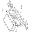
- a copier system 15 includes a printer with a sheet feed and drum transport assembly 17.
- the printer may be of the ink jet type having ink jet nozzles (not shown) carried by an array transport system 250.
- Copier.system 15 provides control and sequencing for sheet feed and drum transport assembly 17 and for array transport system 250.
- the ink jet nozzles may be driven by input data from a document scanning system which includes a scanner and a source organizer to feed a data memory with the image data being stored and then applied to the ink jet arrays.
- a document scanning system is described in U. S. Patent Specification No. 4,069,486.
- Assembly 17 of copier system 15 has a rotary drum 10 to which are fed single flexible sheets 11 from bin 12 by conveying belts 13. After being processed, the sheets are fed by the same belts 13 from drum 10 to an output bin 14.
- Conveyor belts 13 are mounted on driving roll 20 and on idle roll 21.
- a vacuum plenum 22 is provided interior to belts 13 with the plenum being connected by way of a conduit 23 to a vacuum source.
- a solenoid 29 operates a mechanical paper gate of assembly 17 into the sheet path between guides 26 and 27 to prevent any sheet from proceeding to drum 10 until that sheet is released.
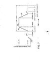
- Drum 10 is driven in a load mode and in a print mode by a drum motor and servo assembly 62. These modes are shown in Fig. 7 in which the load modes are indicated by segments 70, 71 and the print mode by segment 72.
- segment 71 will be called a load mode even though it actually comprises both an unload and a load mode.
- vacuum control 19 is coupled to drum 10 with conduits to provide both vacuum and pressurized air. Specifically, control 19 is effective to provide leading edge and trailing edge vacuum as well as pressurized air, to effect loading, J unloading and maintainence of a loaded sheet on the drum.
- Figs. 4 and 5 show most of the details of the control and sequencing system for the sheet feed and drum transport assembly 17 and array transport system 250. A portion of this system as applied to array transport system 250 is also shown in Fig. 3.
- the system includes microprocessor 300 which may be programmed by firmware and has input ports 104-107 and output ports 110-114. Output port 111 supplies signals to the drum motor and servo assembly 62 and the assembly supplies signals to input port 104. Output port 112 provides signals to the TPT servo assembly 264 (Figs. 1 and 3) which in turn provides input signals to input port 105.
- Selected inputs and outputs of input port 107 and output port 114 are coupled to an operator's panel which includes display 230, ten key pad 243, start key 30, and stop- reset key 241.
- the remaining input and output ports are coupled to sheet feed and drum transport assembly 17 and vacuum control 19 as shown in Fig. 1.
- Output port 111 is coupled by way of a line 84a to a low an acceleration waveform to drive motor 60 of assembly 62 from a stop to a load speed.
- the output from circuit 84 is applied to a switch 90 which is operated by a load speed detector circuit 91 to a one state. In this one state, the output of circuit 84 is applied by way of switch input 90a and output 90c and through a power amplifier 92 to motor 60.
- Amplifier 92 is effective to convert the voltage input signal to a drive current.
- motor 60 accelerates drum 10 from a stop to a load speed 70, as shown in the waveform of Fig. 7, in accordance with the signal from circuit 84.
- Motor 60 is coupled to a tachometer 95 which provides a tach signal to both a load speed detector circuit 91 and a load speed servo circuit 96.
- Circuit 91 is thus switched into operation when the pulse rate from tachometer 95 is within a specified percentage of the desired load speed.
- circuit 91 is effective to switch circuit 90 from a one state to a two state.
- switch 90 connects switch input 90b to output 90c.
- switch 90 switches back to its one state.
- switch 90 applies the output of load speed servo 96 to power amplifier 92.
- the drum at speed line 212 supplies a signal to port 104 of microprocessor 300.
- Tachometer 95 is also connected by way of an index output line 116 to input port 104.
- the input signal on line 116 occurs once per drum revolution and indicates a specific rotational position of drum 10. More frequent pulses are produced by tachometer 95 on tach line 210 which is also applied to input port 104.
- a high speed detector 138 is similar to low speed detector 91 except that it operates at a substantially higher frequency. With motor 60 not at high speed, no signal is applied on line 139 and switch 134 is in the one state. Since switch 134 operates similarly to switch 90, switch 134 connects the output of an accelerate to print speed circuit 131 through switch input 134a and output 134c to power amplifier 92. Accordingly, the amplifier responds to the waveform from circuit 131 thereby to drive motor 60 to accelerate from load speed to print speed as shown by segment 74, Fig. 7. Upon reaching print speed, circuit 138 provides a signal on line 139 through AND gate 141 to actuate switch 134. As a result, switch 134 then connects high speed servo 140 to amplifier 92. Accordingly, as shown in Fig. 7, system 15 is brought to print speed 72 and may begin printing a copy.
- load speed circuit 146 is effective through switch 90 to provide a deceleration waveform to amplifier 92.
- a signal on line 146a is effective by way of inverter 142 to block AND gate 141 so that no signal is applied from detector circuit 138 to switch 134.
- Load speed detector 91 and load speed servo 96 then function in the manner previously described to take over the drive of motor 60.
- the specific inputs and outputs of input ports 104-107 and output ports 110-114 will later be described with respect to the operation of system 15.
- Fig. 3 shows array transport system 250 and a velocity waveform 285 of transport 254 formed of a scanner and printer coupled together.
- Transport 254 is secured to a wheeled carriage 256 which rides on rails 252.
- Carriage 256 is driven by a servo motor 262 by way of a steel tape 262a.
- Servo motor 262 has a shaft which is coupled to a tachometer 260.
- Servo motor 262 is energized by a power amplifier 258 which is in turn controlled by a TPT (transport) servo 264 which is also coupled to tachometer 260.
- TPT servo 264 has two outputs, TPT at speed line 208 and TPT tachometer line 202, both coupled to input port 105.
- the inputs to TPT servo 264, TPT move home line 194 and TPT move away line 196, are coupled to output port 112.
- a pair of photosensors viz., home end sensor 204a and away end sensor 206a, which are actuated by a flag which is riding on transport carriage 256.
- home end stop 290 which is at the extreme home end of rails 252 and away end stop 292 which is at the extreme away end of the rails.
- home end sensor 204a defines the distance between stop 290 and its closest respective edge of the paper while sensor 206a defines the distance between stop 292 and its closest respective edge of the paper 11. It will be understood that when transport 254 leaves the home end or the away end, its acceleration should always be complete before reaching the closest respective edge of paper 11 so that printing is accomplished at a steady rate.
- microprocessor 300 may be an I/O processor used with the IBM Series I computer.
- a master power on switch 80 (Fig. 5), is actuated and INIT is accessed.
- the first operation is a reset signal on line 224 applied to POWER ON RESET (POR latch 324, Fig. 6).
- a COPY REQUEST flag is also reset.
- turning on the MAIN POWER RELAY brings up line 201 in Fig. 4.
- the code drops through another entry, INIT1, paragraph 4.2, which is entered after handling an error, such as a jam. This is the location the code would enter after a jam has been cleared.
- PROFILE COMPLETE FLAG is reset.
- This flag is a software flag that is turned on after a successful profile of the system is made. This is effective to force the profile routine in paragraph 15 to be run during the initializing phase.
- LOAD ADJUST FLAG another software flag which will be set when paper 11 has successfully been loaded on drum 10. Meanwhile, a nominal load time of 152 is set into variable CALCLOAD. If the HEAD UP FLAG is off, then a subroutine called INKUP is run.
- INKUP brings up all of the pressures in the ink lines and checks all of the levels in the ink system. If this is successful, the HEAD UP FLAG is set with return to the main program flow.
- the initialize routine in paragraph 4 then turns off the NOT READY LIGHT and the system proceeds to the IDLE routine in paragraph 6 unless the COPY REQUEST flag is on. If this were an error handling case, the RETRY routine in paragraph 4.3 would be executed. If RETRY has been executed, an error light would be displayed in display 230. The operator may then clear the jam and he has two options. In the first option, he may actuate a RESET KEY which cancels the remaining copy run and there is a return to IDLE, paragraph 6.0. As a second option, the operator may actuate the start key or switch 80 after clearing the jam and then the code at STARTIT, paragraph 7, is executed. The run is continued and the required additional number of copies are made so that the total number is correct.
- the IDLE routine waits for the operator to request copies from system 15. This is the normal idle state of system 15.
- the COPIES COMPLETE flag is set to zero and the NO USE TIMER is reset to zero.
- a DOUNTIL loop is then entered and continued until there is a closure of start key 30 or a closure of reset key 241 or any ERROR FLAG comes on or COVER INTERLOCK OPEN is set.
- Ten key pad 243 is then integrated which means that the system takes several successive samples for noise rejection. If the samples are the same, then the switch on pad 243 is actually closed. Thereafter, display 230 is updated with anything that has been keyed in.
- copier system 15 may be a convenience copier and, over a lunch period or a long meeting, may remain idle for a substantially long period of time. During that time, the critical parameters may possibly change. Accordingly, as set forth in paragraph 6, if the NO USE TIMER overflows, then there is a reset of the PROFILE COMPLETE FLAG and the LOAD ADJUST FLAG. Accordingly, a new profile is performed and the nominal paper loading time is also reinitialized.
- a COPY REQUEST flag is set and remains on until the run is completed successfully.
- the DONE FLAG is cleared until the last copy is run.
- energizing signals are applied by way of vacuum motor line 226 and transport motor line 228 from output port 114. If the PROFILE COMPLETE FLAG is off (it will always be off for the first copy of the day), the PROFILE routine, paragraph 15, is called in order to characterize system 15 and to determine the existing running values of the critical parameters during a nonprinting cycle. These actual running values provide a profile and they are stored and used during the subsequent printing cycles.
- the PROFILE routine calls a subroutine STP2LOAD, paragraph 5.9, to bring drum 10 up to load velocity with a minimum of checking since this is not a critical part of the cycling.
- STP2LOAD As shown by the waveform in Fig. 7, velocity at rest is indicated by segment 73 and STP2LOAD routine accelerates drum 10 from this zero velocity segment 73 up to load velocity segment 70.
- TIMER is to be set to 45 milliseconds. This time is set in processor 300 with respect to an oscillator 218, Fig. 8.
- TIMER is loaded with a constant representing 45 milliseconds and there is a countdown once every 125 microseconds which produces a delay of 45 milliseconds.
- the ACCEL TO LOAD SPEED command in block 84 and the LOAD SPEED command in block 146 to the drum 10 are set which brings the drum up from segment 73 to segment 70 in Fig. 7.
- a DOUNTIL loop is then performed until the TIMER counts down by MSTIMER (paragraph 5.2) to zero or until drum 10 applies to input port 104 a DRUM AT SPEED signal by way of line 212, Fig. 4.
- oscillator 218 is in a loop with a series of binary triggers 215a-215n.
- the output of the last binary trigger 215n provides on line 220 a pulse wave shape of 125 microseconds per phase. This wave shape is applied through input port 106, Fig. 4, back to microprocessor 300. In this manner, there is achieved a saving in overhead in microprocessor 300.
- oscillator 218 is sampled. Specifically, every time oscillator line 220 changes, there is an update in TIMER function which is a count in one of the registers in microprocessor 300. If oscillator line 220 has changed, TIMER is updated and if it has not changed, the program returns to the main program flow.
- the MSTIMER routine tracks line 22 as long as these calls are not too far apart.
- the program After each call of MSTIMER, the program responds to the value of TIMER and at the DRUM AT SPEED line 212. Two events can bring the program out of this DOUNTIL loop. The first event is that TIMER reaches zero before drum 10 accelerates to load speed 70 which indicates that there is a defective drum. In that event, ERROR FLAG 2 is set and an error handling routine is called. In the second event, the DRUM AT SPEED line 212, Fig. 4, provides a signal before TIMER equals zero which indicates that the drum accelerated in a satisfactory manner. In the second event, the program returns to the caller and the PROFILE routine is returned to.
- CKLDVEL check load velocity
- This routine insures that after the drum accelerates from stop segment 73 to load speed 70, Fig. 7, drum 10 is actually stabilized at segment 70 at an acceptable velocity so that paper may be loaded.
- a microprogrammed loop is now used to count microprogrammed cycles within the loop using microprocessor 300 as a clock for this function.
- the program responds to transisitions of tachometer line 210 to time eight of such transitions and ascertains that these eight transitions take place within an acceptable time window tolerance as determined by service requirements.
- a variable called COUNT is now set to zero and placed in a register in microprocessor 300.
- Another function, viz., LOOP is set to zero and is also placed in a register in microprocessor 300.
- the present state of TACHOMETER from tachometer 95 is placed in register NOW.
- a DOUNTIL loop is started and the loop is continued until tachometer 95 produces an output not equal to NOW.
- a change in the value of TACHOMETER is being checked for.
- a routine, GETPU L S, paragraph 5.3, later described in detail is called. This routine essentially keeps track of tachometer 95. It is desired to be on the edge of a TACHOMETER change so that the timing may be started which continues until the TACHOMETER count equals eight. In this manner, as TACHOMETER is sampled, the routine also increments LOOP for each sample.
- the LOOP variable is the accummulated number of times that the TACHOMETER sample loop was executed. If the incremented LOOP is more than a predetermined maximum or less than a predetermined minimum, an ERROR FLAG 2 is set which designates a drum error and an error handling routine is called. If LOOP is between these two constants, then the program returns to the main program flow which indicates that load velocity 70 is within the proper limits.
- the program returns to PROFILE, paragraph 15, and sets TIMER to 257 milliseconds. This is a little over one revolution of drum 10 at load velocity 70. It is now determined whether a pulse is present on index line 116 which is coupled to input port 104. If the index pulse is not present, there is no reference to the position of drum 10. Accordingly, TIMER is set to a value representing little more than the time of one revolution of drum 10 and another DOUNTIL loop is executed until TIMER is zero or an INDEX FLAG is seen. MSTIMER, paragraph 5.2 is called to count down the TIMER and GETPULS is called, paragraph 5.3, which tracks tachometer 95.
- an INDEX FLAG is first reset and the signal on tachometer line 210 is received as is INDEX PULSE on line 116 from input port 104. If the INDEX PULSE is on, the INDEX FLAG is set and then the TACH COUNT is zeroed to prevent accummulated errors. If the INDEX PULSE is not on, then TACHOMETER readings are compared and if the TACHOMETER reading is the same as the last sample, then the program returns to the caller. If the TACHOMETER reading is different, then TACH COUNT is incremented and there is a return to the main program. It will be understood that on the average, GETPULS must be called at least once during each tach pulse so that none of these pulses are missed.
- the PROFILE routine calls GETPULS the first time it is going to correct the OLDTACH flag and may make one erroneous count. However, after that, the first time an index is detected on line 116, there is a locking into the correct count and thereafter the correct count is kept. If the program comes out of the DOUNTIL and TIMER is not zero, then the index is working correctly.
- drum 10 is brought up to print speed and TIMER is set to 700 milliseconds which is the value of maximum allowable time.
- TIMER is set to 700 milliseconds which is the value of maximum allowable time.
- blocks 84 and 146 have previously been set to reach load speed.
- blocks 84 and 146 are dropped and print speed block 131 is raised.
- a DOUNTIL is then executed until either timer equals zero or DRUM AT SPEED signal 212 comes up using MSTIMER, paragraph 5.2. If TIMER reaches zero, this indicates a drum error. Otherwise, the routine returns to the main program flow.
- TIMER had been set at 700 milliseconds as a safety time out. Accordingly, when the program returns to the main program, whatever is left in TIMER is a measure of how long drum 10 actually took to get up to that speed. This residual of elapsed time is arithmetically converted in the processor 300 and is stored as ACCTIM (accelerate time) which is an existing running value of a critical parameter determined during this nonprinting profile cycle.
- TIMER is set at 33 milliseconds which is one millisecond more than a full revolution of drum 10 at print velocity 72.
- the routines MSTIMER and GETPULS are called in the manner previously described and a DOUNTIL loop is performed also in the manner previously described. The results determine if the index pulse is occurring properly at the desired high speed.
- print velocity CKPRTVEL paragraph 5.12
- This routine times the interval between two successive index pulses to ensure correct print speed 72, Fig. 7.
- CKPRTVEL, paragraph 5.12 and CKLDVEL, paragraph 5.11 operate similarly.
- the resolution is not quite the same so that instead of timing eight tachometer pulses on line 210, the timing is from index to index which comprises 256 tach pulses.
- drum deceleration 75 Fig. 7.
- This subroutine determines (1) how long it takes to decelerate and (2) how far along the surface of drum 10, this deceleration takes place. For the reasons later to be described, the distance value is preferable to that of time and is accomplished by starting deceleration at the same time as the tachometer indexed on line 116. Then it is determined how many revolutions plus how many TACH COUNTS it takes to decelerate drum 10 until the AT SPEED signal on line 212 again occurs which indicates that the drum is at load speed segment 71. These two measurements are important in determining whether there may be an optimal point of deceleration during actual printing.
- deceleration on segment 75 begin at a time so that the end of the segment 75 is reached at the best time to remove the paper. Specifically this is accomplished by using the index on line 116 as a reference for deceleration segment 75 and the OVERFLOW COUNT (a number in a register in microprocessor 300) is set to zero.
- a LOAD VELOCITY command in block 146 is set which decelerates drum 10 down to load velocity 71.
- TIMER is set to one second as a safety timeout to prevent hang up.
- DOUNTIL is looped until the signal on drum at speed line 212 or TIMER is zero.
- OVERFLOW COUNT tracks the number of drum revolutions which is the number of indexes 116 which have been seen.
- TACH COUNT the fractional part of the drum revolution is calculated so that there is a precise indication of the drum position when the DRUM AT SPEED signal is received. In this manner, at the time of the DRUM AT SPEED signal, there is known the revolutions in the OVERFLOW COUNTER as well as the TACH COUNT and calculation may take place.
- PLSTART is the desired place where deceleration should be started during the print cycle and PLR E VS is the desired number of index pulses that should be seen during the course of the deceleration.
- DRUM AT SPEED should come up 109° from index 116 which is the optimum deceleration. Accordingly, puffer line 152 should be actuated at 80° from index 116 during that last rotation of drum 10.
- the PUFFER should lift the leading edge of the paper so that it will detach from the drum.
- the reference point is effectively determined from which point deceleration should take place in order to reach load speed at the proper position. It will be understood that after profiling and in the use of the stored critical parameters, if the print cycle has not reached this reference point, it is important that the cycle continue at the higher print speed until it reaches the reference point and only then should deceleration take place. This is to be compared with undesirably starting deceleration before the reference point and then rotating at the slower load speed until a proper release point is reached. The preferable operation is performed in the PROFILE routine by considering whether TACH COUNT is greater than 77 or less than 77. If TACH COUNT is greater than 77, then 77 is subtracted from it.
- Routine PR03, paragraph 15.1 may be entered in two ways. The first way is on the initial profile of the day. In the second way, the cabinet of system 15 has been opened or transport 254 has been moved away from stops 290,292. When the cabinet has been opened a signal is produced on interlocks line 222 and when transport 254 has been moved away from stops 290,292, respective sensors 204a,206a feeding lines TPT home 204 and TPT away 206 are not indicating end of travel. During operation either the opening of the cabinet or the transport being away from the stops, is detected in routine STARTIT, paragraph 7, and transport 254 is placed at one edge or the other before printing starts.
- routine PR03 there is first called TPTHOME, paragraph 5.7. This returns transport 254 to home end stop 290 and the only checking being performed is a safety timeout of eight seconds.
- the MOVE HOME command on line 194 is transmitted to transport 254 until the TIMER counts down to zero or home sensor 204a provides a signal 280 on home sensor line 204.
- ERROR FLAG 5 is set if TIMER reaches zero before signal 280 appears on sensor line 204. If there is no error, TPT move home line 194 is dropped or the signal is removed and the routine returns to the caller at PR03.
- the following profiling determines the amount of time it takes for transport 254 to go from stop 290 to the closest or adjacent edge of the paper. This time will be measured and stored.
- TIMER is set to one second and the signal on TPT move away line 196 is raised. It will be understood that it is necessary that transport 254 be at print speed 284 as shown on the velocity curve before pulse 280 reaches its falling edge 280a.
- the routine also measures and tests the amount of time it takes to reach the adjacent paper edge.
- MSTIMER paragraph 5.2
- the loop continues until TIMER counts to zero which is an error indicated by FLAG 3. On the other hand, if TIMER does not count out, then the edge of the paper has been reached. Following this loop, one second is subtracted from the value in TIMER and the result complemented giving the elapsed time. This elapsed time is stored in the home time register (HOMETIM). This is one of the calculated transport profile parameters. Thereafter, routine transport velocity (TPTVEL) is called and checked to determine that there is a proper velocity for printing.
- HOMETIM home time register
- TPTAWAY paragraph 5.8, which is similar to TPTHOME previously described except that its measurements are with respect to away end stop 292. Since printing is done in both directions, the same measurements are performed from stop 292 to the adjacent edge of paper on the away end as was previously performed on the home end. Accordingly, a similar procedure is performed and if there is no error, the resultant elapsed time is stored in AWAYTIM. In the manner previously described, to assure that transport 254 is up to velocity after leaving stop 292, transport velocity (TPTVEL) is again called. Then, TPTHOME, paragraph 5.7, is called to get the transport 254 against stop 290 on the home end. The home delay (HDLY) and the away delay (ADLY) are then calculated as described in the program listing.
- HDLY home delay
- ADLY away delay
- HDLY is a critical parameter determined during this nonprinting cycle, the existing running value of which is equal to the time difference between (1) the drum accelerate time to print speed and (2) the time that array transport 254 takes to accelerate from home end stop 290 to the closest edge of the paper.
- ADLY is a critical parameter, the actual running value of which is equal to the time difference between (1) the drum accelerate time to print speed and (2) the time that transport 254 takes to accelerate from stop 292 at the away end to the closest edge of the paper.
- drum and transport profile which may be summarized as follows:
- a critical operating parameter is defined for purposes herein as a selected one of the many operating parameters of system 15 which determines or is otherwise material to the performance of the system.
- a profile taken of a critical parameter is defined for purposes herein as a measurement of the actual value of a critical parameter preferably taken (1) during the start of operation (or restart after an error) and (2) during a nonprinting cycle. During such a nonprinting cycle, system 15 is fully functional but sheet 11 is not moved and no ink is applied. It will be understood that only critical parameters are measured during the nonprinting cycle, except for DECTIM in this embodiment.
- the STARTIT routine, paragraph 7, is now entered and the PROFILE COMPLETE FLAG is first tested. Depending on the manner in which STARTIT has been reached from the program flow as shown in the listing, a profile may or may not be performed in the manner previously described. Thereafter, the routine determines if the home and away sensors 204a,206a are both off in which case PR03, paragraph 15.1, is called. RETRY COUNT and COPIES COMPLETE are then set to zero.
- the PICK routine paragraph 8, is now executed to remove paper 11 from input bin 12. It can be seen that the correct paper bin is selected for input of sheets 11.
- a COCK PICKER command to PAPER PICKER provides a wait of 65 milliseconds until there is a pull back. This command is then dropped and at that time, a finger shoots forward and pushes a single sheet of paper into the feed. After waiting 130 milliseconds, the paper should be under the paper entry sensor line 234, Fig. 5. If that line is not high, there is a picker failure so that the RETRY COUNT is incremented. This is tried eight times and, if it is not successful, the ERROR FLAG 4 is set and the routine jumps to ERROR.
- the routine waits 250 milliseconds for paper 11 to move down the path into proximity of a paper gate in accordance with the signal on paper gate line 236 which signal indicates the presence of paper 11. After that 250 milliseconds, GATE SENSOR is checked and if the GATE SENSOR is off, ERROR FLAG 4 is set as there must be a jam in the input because the paper reached the entry but didn't reach the gate. If no ERROR FLAGS have been raised, then a sheet is at the gate, ready to be loaded on the drum 10.
- the LOAD routine follows in which the trailing edge vacuum on line 170, Figs. 4 and 5, is turned off. These ports are to be closed so that there is additional vacuum on the leading edge of the paper.
- the DOUNTIL loop is executed calling GETPULS, paragraph 5.3, until index line 116 applies a signal. In this way, the index is found and TACH COUNT is initialized.
- the LOAD ADJUST FLAG is the flag set whenever a successful load has been accomplished. It indicates that the time required for the paper to get to the correct apper position on rotating drum 10 has been determined. If that flag is reset, this indicates that a calculation has not as yet been made. Accordingly, it is desired to set a tachometer count of 152 (related to a nominal load time) into a TEMP register, which is one of the program registers in microprocessor 300. In conventional copier systems, that load time would be the constant load time for the system. This time is calculated to be an effective safe time to open the paper gate of sheet feed and transport assembly 17. This safe time is not necessarily optimum but is calculated to get the paper safely on drum 10.
- CALCLOAD is a variable defining a critical parameter which is a predetermined calculated time stored in memory.
- TACH COUNT is a calculated load value
- GETPULS is called which tracks tachometer 95.
- TACH COUNT equalling the value in TEMP
- a pulse is produced on open gate solenoid line 120 which opens the paper gate in assembly 17 starting paper 11 towards drum 10.
- the drum continues to be tracked by the next DOUNTIL until TACH COUNT equals 113. Accordingly, GETPULS is called to update the TACH COUNT.
- TEMP register is set to the TACH COUNT because as long as the paper still has not reached the sensor, TEMP is updated with TACH COUNT for every pass through this loop.
- the last updated value of the TEMP register remains in that register which provides an indication of the time paper 11 arrived. This allows the determination of a new CALCLOAD which defines the actual running value of a parameter related to the drum position at the time of releasing the paper.
- CALCLOAD is now loaded into TEMP2 and CORRECT is set to a desired tach count which is the count at which the paper should have arrived at the sensor.
- TEMP is less than CORRECT
- the paper arrived early and TEMP2 is added to half the difference between CORRECT (the time it should have arrived at the sensor) and TEMP (the time it actually arrived at the sensor).
- the difference is halved because the correction is applied in a direction to cause the paper to arrive late. If the arrival is too late, paper 11 will not stick on drum 10 because the vacuum holes of the drum will be uncovered. Only half the error is added to scale it so that the correction does not inadvertently become too great and the vacuum holes remain uncovered after the paper arrives.
- CALCLOAD is updated with TEMP2 less the correction factor of TEMP minus CORRECT. That is to say, the paper gate in assembly 17 is opened earlier in the next loading by the full amount of the error. If the paper were late, it would have tended to uncover the vacuum holes and it is important to correct this quickly by the full error amount so that the vacuum holes can be safely covered. In both cases, the corrections are stored as variable CALCLOAD.
- the LOAD ADJUST FLAG is set since the time to open the paper gate has now been adjusted. It will be understood that the foregoing adjustment of the paper arrival time is accomplished at load time. It is not done during profiling since it is not desired that paper actually be moved through system 15 during profiling and into output bin 14. Thus paper is not moved during the profile process and this self adjustment feature for the paper is achieved during the first copy cycle, i.e., the first time paper is moved through system 15. In this manner, there is provided a feedback adjustment of the paper position during the actual copying process rather than prior to the actual copying process.
- the trailing edge vacuum solenoid line 170 is then dropped which causes vacuum to be directed to the tailing edge so that it tacks down paper 11 when the paper reaches that point. Furthermore, the gate solenoid line 120 is also dropped and a PRINT SPEED command to block 131 may be set so that drum 10 accelerates up to PRINT SPEED.
- drum 10 Since PRINT SPEED has been set, drum 10 is accelerating and the LOAD 1 routine, paragraph 10.1, is now executed. It will be understood that with drum 10 accelerating, the profile parameter HDLY or ADLY is now used to determine when to start the movement of transport 254. As previously described, drum 10 always takes longer to get to speed than moving transport 254 takes to get to the edge of the paper. It is desired to have a delay before transport 254 starts so that it does not get to the edge of paper 11 too quickly. Accordingly, TIMER has been loaded with the interval between startup of drum 10 to PRINT SPEED and startup of transport 254 from stops 290, 292 so that the drum reaches print velocity just before the transport reaches the edge of the paper. This has been accomplished by TIMER with HDLY if the transport is on the home end or ADLY if the transport is at the away end.
- a DOUNTIL loop is executed until TIMER equals zero.
- GETPULS paragraph 5.3
- MSTIMER paragraph 5.2 continues to track oscillator line 220.
- home sensor 204a on indicates that transport 254 is at the home end against home stop 290 and segment 284a of velocity curve 285 is applicable.
- away sensor 206a on indicates that transport 254 is at the away end against away stop 292 and velocity segment 284e is applicable.
- TIMER is set to 250 milliseconds which is a safety delay to insure against system errors or malfunctions.
- Another DOUNTIL loop is then executed until a respective sensor 204a, 206a turns off as indicated by falling edges 280a, 282a, respectively, or in case a malfunction TIMER is counted down to zero. If the TIMER counted down, then ERROR FLAG 5 is set and the system jumps to ERROR because start of print has not been reached within an allowable time. If TIMER had not counted to zero, drum 10 is up to speed as previously described, transport 254 is at the edge of the paper 11, and system 15 is ready to print.
- the system detects whether paper 11 has fallen off the drum 10 during drum acceleration 74, Fig. 7. Specifically, the paper on drum 10 is checked by way of photosensor signal on a paper on drum line 240 from sheet feed and transport assembly 17. Line 240 is coupled to input port 107. If paper 11 is still on drum 10, then the PRINT routine, paragraph 12, is called or else an ERROR FLAG 4 is set which indicates loss of paper and system 15 jumps to ERROR.
- COPIES COMPLETE equals COPIES REQUESTED
- a DONE FLAG is set so that no more sheets of paper 11 are fed. It will be understood that a revolution counter is included in the registers of microprocessor 300 and used as a microcoded counter register.
- REVOLUTION COUNTER At every ten counts of REVOLUTION COUNTER, a series of checks are made. This is done by a case statement which states that if a case is met, the listed action will be performed. Accordingly, at every ten counts of the REVOLUTION COUNTER, the reset switch line 241, which is coupled to input port 107, and the interlocks line 222, which is coupled to input port 106, are examined. For example, if line 241 indicates that a reset switch has been actuated, a DONE FLAG is turned on so that the copy being printed is the last one. If a cover interlock has been opened, ERROR FLAG 7 is set and the program goes to ERROR to shut system 15 down. In similar manner, other checks are made and other actions are executed.when the REVOLUTION COUNTER equals 1, 11, 21, 31, 206, 208, 212, 220 and 221 as set forth in the program.
- the SLOWUP routine is now entered to stop transport 254 and to decelerate drum 10.
- This routine uses two variables of the profile, specifically PLREVS and PLSTART.
- PLREVS is the number of index pulses during drum deceleration which was set to end at 109°.
- PLSTART is the number of tachometer output pulses required to start decelerating from print to load velocity. Accordingly, PLREVS is loaded into COUNT and PLSTART is loaded into COMPARE.
- a DOUNTIL loop is performed until TACH COUNT equals PLSTART and either of TPT home line 204 or TPT away line 206 is up. System 15 waits for two events.
- One of the events is for transport 254 to reach either home or away end so that deceleration of the transport may begin.
- the reason for this first condition is that the 224 revolutions previously counted is actually somewhat short of sensors 204a, 206a.
- TACH COUNT equals COMPARE (PLSTART having been loaded into COMPARE)
- system 15 sets the LOAD SPEED command in block 146 to drum 10. From the profiling, this is the optimum time that has been determined for beginning of deceleration. If TPT home line 204 or TPT away line 206 is up, then there is a corresponding drop in move home line 194 and move away line 196 to decelerate transport 254 so that it won't crash into respective stops 290, 292. Thereafter, if INDEX FLAG (set from index line 116) is on, there is a decrement in COUNT. Therefore, when the system comes out of END DOUNTIL, both transport 254 and drum 10 are decelerating.
- INDEX FLAG set from index line 116
- GETPULS paragraph 5.3
- leading edge puff line 152 is brought up. This signal is maintained until drum-at-speed line 212 goes up which occurs at approximately 109° of revolution of drum 10. It will be understood that it may not be exactly 109°, depending upon the accuracy of the calculations and whether system 15 is changing with time.
- GETPULS, paragraph 5.3 is called until the drum-at-speed signal occurs on line 212.
- RECALC routine is executed when drum-at-speed line 212 comes up.
- the data in TACH COUNT (the count at which the signal occurred on drum-at-speed line 212) is set into NOW.
- Line 212 should have come up at 109° if nothing in system 15 had changed with time and everything had been correctly calculated. Accordingly, if TACH COUNT equals 109°, then no further calculations are performed. If NOW is greater than 77, this would indicate drum 10 had arrived late at load speed and routine LATE is called, paragraph 13.2. In this routine, there is a slight change in parameters to perform a feedback function.
- routine EARLY paragraph 13.3, is called.
- a DONE FLAG is checked and, if it is set, the system calls LASTOUT, paragraph 14, which indicates that the last copy of paper 11 has been run and the copy is tracked to output bin 14.
- System 15 returns to IDLE routine, paragraph 6. If the DONE FLAG is not set, system 15 goes to the NEXT routine, paragraph 10, which loads the next sheet 11 on drum 10 for a multiple copy run.
- the LATE routine indicates that drum 10 had not quite reached speed soon enough. Accordingly, PLSTART and PLREVS are loaded so that they can be adjusted. It will be understood that arriving late is more critical than arriving early since a late arrival may cause difficulty with the detachment of sheet 11. On the other hand, an early arrrival means that the time to detach the sheet is lengthened. Thus, in the LATE routine, the entire error is subtracted from PLSTART and PLREVS. A new PLSTART is calculated and if a borrow is required, then PLREVS is decremented. Following these calculations parameters PLREVS and PLSTART are stored.
- LASTOUT routine paragraph 14 is performed. 250 milliseconds are required for sheet 11 to be detached from drum 10. If an exit sensor in assembly 17 is actuated, a "remove copies" light is lit in display 230. In addition, after one second for the copy to clear the exit path, output port 114 provides dropping signals on vacuum motor line 226 and TPT motor line 228 to servo motor 262. System 15 then returns to IDLE, paragraph 6.
- system 15 goes to NEXT, paragraph 10, which is the routine that loads paper. As previously described, a new sheet 11 is then loaded and a new print cycle is initiated.
- the ERROR FLAGS are listed in paragraph 16 and need not be described in detail. It is understood that after an ERROR FLAG has been set, the ERROR routine is executed as set forth in paragraph 17, and the profile complete flag is reset, thereby producing a new profiling. After an ERROR, and during possible repairs, a sensor may be changed in position or other changes may be made to copier system 15 which requires a new profiling.
- Fig. 6 is, a block diagram showing the physical implementation of microprocessor 300 and its buses as well as input and output ports 104-107 and 110-114.
- microprocessor 300 has an output data bus 100 and an input data bus 102 as well as an eight-bit address bus 306 and a control strobe line 370.
- Address bus 306 allows microprocessor 300 to address up to 256 input and output ports.
- Control strobe line 370 is used with bus 100 to set information into an output port which is shown, for example, in Fig. 6 as output gate latches 334, 336 and 338.
- Address bus 306 signals are decoded by decoder 314 to gate the output gate latches.
- the addresses may be decoded by decoder 312 to select input ports which, for example, are shown as AND gates 318, 320 and 322 which are typical input ports.
- a gated decoder 316 is provided which controls the addressing range of an extended address functions decode block 332.
- a power on reset latch 324 is provided which is turned on whenever the power is brought up on system 15. Latch 324 resets all the output ports of microprocessor 300 until the resetting of latch 324 by way of line 224.
Landscapes
- Accessory Devices And Overall Control Thereof (AREA)
- Handling Of Cut Paper (AREA)
- Controlling Sheets Or Webs (AREA)
- Facsimile Scanning Arrangements (AREA)
- Saccharide Compounds (AREA)
- Control Of Motors That Do Not Use Commutators (AREA)
- Non-Silver Salt Photosensitive Materials And Non-Silver Salt Photography (AREA)
- Discharging, Photosensitive Material Shape In Electrophotography (AREA)
- Fax Reproducing Arrangements (AREA)
- Printers Or Recording Devices Using Electromagnetic And Radiation Means (AREA)
- Character Spaces And Line Spaces In Printers (AREA)
- Handling Of Sheets (AREA)
Abstract
Description
- The present invention relates to printing devices and methods of operation thereof.
- In many printing devices in the prior art, the operations of the separate moving components were linked to act in sequence by mechanical linkages. Other devices, such as a film printer described in U.S. Patent Specification No. 3935434, employed electrical control signals to determine the sequence of operation of the components. In each of these devices, certain operating parameters are critical to the correct working of the machine, and it operates satisfactorily while these critical parameters are within certain tolerances. There have been two basic choices in setting up such tolerances for printer operation. First, if the printer is set to function within a narrow tolerance band, the printer then has good operating performance while the critical parameters remain within that band. This usually requires frequent and costly service calls by service personnel to maintain satisfactory operation by adjusting those narrow tolerances. Secondly, printers set up with a wide tolerance band at the factory result in machines having large performance variations among machines. For example, where a critical parameter involves the speed of the machine, with a wide band of tolerances a fast machine will sometimes give poorer overall performance.than a slower machine though both machines are within the tolerance band. Thus, in a particular example of an ink jet printer, using a print drum to transport sheets a fast acting servo actually causes the system to perform more poorly than a slower acting servo because a fast servo brings the print drum down to load speed quickly. The print drum, however, must remain at the lower load speed until a paper load point on the drum has been reached since the printer can accept paper only at certain load points. Thus, there has been no gain, but rather a loss, in efficiency when the drum reaches a slow load speed at an early time. For maximum system efficiency, the fast servo should have remained longer at the faster print speed in order that a load point on the drum be brought up sooner.
- Accordingly, it is an object of the invention to provide a printing device and a method of operation thereof which is arranged to permit efficient operation of the various components taking into account the critical operating parameters.
- In one aspect of the invention, there is provided a printing device including sheet feeding means for feeding sheets through a printing station and means for transporting a print mechanism at the printing station, characterised in that said feeding and transporting means are driven independantly in response to output control signals from a digital processor which receives, as its inputs, sensor data signals from the feeding and transporting means, said processor including means for selecting predetermined sensor data values during a non-printing profile cycle of the device as critical operating parameters, means for storing said critical operating parameter values and for employing the stored parameter values as operating parameters during a printing cycle subsequent to a profile cycle.
- In another aspect of the invention, there is provided a method of operating a printing device including sheet feeding means for feeding sheets through a printing station and means for transporting a print mechanism at the printing station and characterised in that said feeding and transporting means are driven independantly in response to output control signals from a digital processor which receives, as its inputs, sensor data signals from the feeding and transporting means including the steps of selecting predetermined sensor data values during a non-printing profile cycle of the device as critical operating parameter values, storing said critical operating parameter values and subsequently employing the stored parameter values as operating parameters during a printing cycle of the device.
- The invention will now be described, by way of example, with reference to the accompanying drawings, in which:
- Fig. 1 is a perspective view of a copier system having a printer with a controlled and sequenced sheet feed, drum and array transport of the present invention;
- Fig. 2 is a velocity waveform useful in explaining the operation of Fig. 3;
- Fig. 3 is a diagrammatic illustration of an array transport system of Fig. 1;
- Figs. 4 and 5 taken together form a block diagram of the control and sequencing system for the sheet feed, drum and array transport of Figs. 1 and 3;
- Fig. 6 is a block diagram of the microprocessor and its buses and ports shown in Figs. 1, 4 and 5;
- Fig. 7 is a velocity profile of the drum of Fig. 1; and
- Fig. 8 is a block diagram of a loop including an oscillator and microprocessor of Figs. 1, 4, 5 and 6.
- In Fig. 1, a
copier system 15 includes a printer with a sheet feed and drum transport assembly 17. The printer may be of the ink jet type having ink jet nozzles (not shown) carried by anarray transport system 250.Copier.system 15 provides control and sequencing for sheet feed and drum transport assembly 17 and forarray transport system 250. The ink jet nozzles may be driven by input data from a document scanning system which includes a scanner and a source organizer to feed a data memory with the image data being stored and then applied to the ink jet arrays. Such a document scanning system is described in U. S. Patent Specification No. 4,069,486. - Assembly 17 of
copier system 15 has arotary drum 10 to which are fed singleflexible sheets 11 frombin 12 byconveying belts 13. After being processed, the sheets are fed by thesame belts 13 fromdrum 10 to anoutput bin 14.Conveyor belts 13 are mounted ondriving roll 20 and onidle roll 21. Avacuum plenum 22 is provided interior tobelts 13 with the plenum being connected by way of aconduit 23 to a vacuum source. Asolenoid 29 operates a mechanical paper gate of assembly 17 into the sheet path betweenguides drum 10 until that sheet is released.Drum 10 is driven in a load mode and in a print mode by a drum motor andservo assembly 62. These modes are shown in Fig. 7 in which the load modes are indicated bysegments 70, 71 and the print mode by segment 72. For the purpose of definition herein, segment 71 will be called a load mode even though it actually comprises both an unload and a load mode. - In conventional manner,
vacuum control 19 is coupled todrum 10 with conduits to provide both vacuum and pressurized air. Specifically,control 19 is effective to provide leading edge and trailing edge vacuum as well as pressurized air, to effect loading, J unloading and maintainence of a loaded sheet on the drum. - Figs. 4 and 5 show most of the details of the control and sequencing system for the sheet feed and drum transport assembly 17 and
array transport system 250. A portion of this system as applied toarray transport system 250 is also shown in Fig. 3. In Figs. 4 and 5 the system includesmicroprocessor 300 which may be programmed by firmware and has input ports 104-107 and output ports 110-114. Output port 111 supplies signals to the drum motor andservo assembly 62 and the assembly supplies signals toinput port 104.Output port 112 provides signals to the TPT servo assembly 264 (Figs. 1 and 3) which in turn provides input signals to input port 105. Selected inputs and outputs ofinput port 107 andoutput port 114 are coupled to an operator's panel which includesdisplay 230, tenkey pad 243, startkey 30, and stop-reset key 241. The remaining input and output ports are coupled to sheet feed and drum transport assembly 17 andvacuum control 19 as shown in Fig. 1. - Output port 111 is coupled by way of a
line 84a to a low an acceleration waveform to drivemotor 60 ofassembly 62 from a stop to a load speed. The output fromcircuit 84 is applied to aswitch 90 which is operated by a loadspeed detector circuit 91 to a one state. In this one state, the output ofcircuit 84 is applied by way of switch input 90a andoutput 90c and through apower amplifier 92 tomotor 60.Amplifier 92 is effective to convert the voltage input signal to a drive current. As a result,motor 60 acceleratesdrum 10 from a stop to aload speed 70, as shown in the waveform of Fig. 7, in accordance with the signal fromcircuit 84. -
Motor 60 is coupled to atachometer 95 which provides a tach signal to both a loadspeed detector circuit 91 and a loadspeed servo circuit 96.Circuit 91 is thus switched into operation when the pulse rate fromtachometer 95 is within a specified percentage of the desired load speed. When the pulse rate enters the desired frequency band,circuit 91 is effective to switchcircuit 90 from a one state to a two state. When in the two state,switch 90 connectsswitch input 90b to output 90c. In the absence of a signal online 98, switch 90 switches back to its one state. Accordingly, when actuated to the two state,switch 90 applies the output ofload speed servo 96 topower amplifier 92. Whendrum 10 has reached load'speed, the drum atspeed line 212 supplies a signal toport 104 ofmicroprocessor 300. -
Tachometer 95 is also connected by way of anindex output line 116 toinput port 104. The input signal online 116 occurs once per drum revolution and indicates a specific rotational position ofdrum 10. More frequent pulses are produced bytachometer 95 ontach line 210 which is also applied toinput port 104. - Furthermore, a high speed detector 138 is similar to
low speed detector 91 except that it operates at a substantially higher frequency. Withmotor 60 not at high speed, no signal is applied online 139 andswitch 134 is in the one state. Sinceswitch 134 operates similarly to switch 90,switch 134 connects the output of an accelerate toprint speed circuit 131 throughswitch input 134a andoutput 134c topower amplifier 92. Accordingly, the amplifier responds to the waveform fromcircuit 131 thereby to drivemotor 60 to accelerate from load speed to print speed as shown bysegment 74, Fig. 7. Upon reaching print speed, circuit 138 provides a signal online 139 through ANDgate 141 to actuateswitch 134. As a result, switch 134 then connects high speed servo 140 toamplifier 92. Accordingly, as shown in Fig. 7,system 15 is brought to print speed 72 and may begin printing a copy. - In deceleration as shown by
segment 75, Fig. 7, load speed circuit 146 is effective throughswitch 90 to provide a deceleration waveform toamplifier 92. A signal online 146a is effective by way ofinverter 142 to block ANDgate 141 so that no signal is applied from detector circuit 138 to switch 134. In this manner,motor 60 anddrum 10 are decelerated to the load speed.Load speed detector 91 andload speed servo 96 then function in the manner previously described to take over the drive ofmotor 60. The specific inputs and outputs of input ports 104-107 and output ports 110-114 will later be described with respect to the operation ofsystem 15. - Fig. 3 shows
array transport system 250 and avelocity waveform 285 oftransport 254 formed of a scanner and printer coupled together.Transport 254 is secured to awheeled carriage 256 which rides onrails 252.Carriage 256 is driven by aservo motor 262 by way of a steel tape 262a.Servo motor 262 has a shaft which is coupled to atachometer 260.Servo motor 262 is energized by apower amplifier 258 which is in turn controlled by a TPT (transport)servo 264 which is also coupled totachometer 260. As previously described,TPT servo 264 has two outputs, TPT atspeed line 208 andTPT tachometer line 202, both coupled to input port 105. The inputs toTPT servo 264, TPT move homeline 194 and TPT move awayline 196, are coupled tooutput port 112. - At both ends of
rails 252, there are provided a pair of photosensors, viz., home end sensor 204a and awayend sensor 206a, which are actuated by a flag which is riding ontransport carriage 256. There is further provided a home end stop 290 which is at the extreme home end ofrails 252 and away end stop 292 which is at the extreme away end of the rails. Thus, home end sensor 204a defines the distance betweenstop 290 and its closest respective edge of the paper whilesensor 206a defines the distance betweenstop 292 and its closest respective edge of thepaper 11. It will be understood that whentransport 254 leaves the home end or the away end, its acceleration should always be complete before reaching the closest respective edge ofpaper 11 so that printing is accomplished at a steady rate. - The operation of
copier system 15 will now be described with respect to the control and sequencing for the sheet feed and drum transport assembly 17 andarray transport system 250. A listing of a program formicroprocessor 300 is attached hereto and is written in a structured format understandable by those of ordinary skill in the art. The operation starts with an initialize sequence. For executing the code,microprocessor 300 may be an I/O processor used with the IBM Series I computer. - As set forth in
paragrah 4 of the listing, to startsystem 15, a master power on switch 80 (Fig. 5), is actuated and INIT is accessed. The first operation is a reset signal online 224 applied to POWER ON RESET (POR latch 324, Fig. 6). At this time, a COPY REQUEST flag is also reset. In the next step, turning on the MAIN POWER RELAY brings upline 201 in Fig. 4. The code drops through another entry, INIT1, paragraph 4.2, which is entered after handling an error, such as a jam. This is the location the code would enter after a jam has been cleared. All the ERROR FLAGs are reset and the NOT READY LIGHT is turned on; remaining on untilsystem 15 is brought up to usable condition which takes some time. Next, the function utility routine reset panel (RSTPNL - paragraph 5.1) is called. This routine brings the operator's panel, paragraph 3, back to power on condition. The COPY REQUEST COUNT is set to one and applied to display 230. - Thereafter, the PROFILE COMPLETE FLAG is reset. This flag is a software flag that is turned on after a successful profile of the system is made. This is effective to force the profile routine in
paragraph 15 to be run during the initializing phase. Also reset is LOAD ADJUST FLAG, another software flag which will be set whenpaper 11 has successfully been loaded ondrum 10. Meanwhile, a nominal load time of 152 is set into variable CALCLOAD. If the HEAD UP FLAG is off, then a subroutine called INKUP is run. - INKUP, described in paragraph 5.5, brings up all of the pressures in the ink lines and checks all of the levels in the ink system. If this is successful, the HEAD UP FLAG is set with return to the main program flow.
- The initialize routine in
paragraph 4 then turns off the NOT READY LIGHT and the system proceeds to the IDLE routine in paragraph 6 unless the COPY REQUEST flag is on. If this were an error handling case, the RETRY routine in paragraph 4.3 would be executed. If RETRY has been executed, an error light would be displayed indisplay 230. The operator may then clear the jam and he has two options. In the first option, he may actuate a RESET KEY which cancels the remaining copy run and there is a return to IDLE, paragraph 6.0. As a second option, the operator may actuate the start key or switch 80 after clearing the jam and then the code at STARTIT, paragraph 7, is executed. The run is continued and the required additional number of copies are made so that the total number is correct. - The IDLE routine, paragraph 6, waits for the operator to request copies from
system 15. This is the normal idle state ofsystem 15. As the first step, the COPIES COMPLETE flag is set to zero and the NO USE TIMER is reset to zero. A DOUNTIL loop is then entered and continued until there is a closure of start key 30 or a closure of reset key 241 or any ERROR FLAG comes on or COVER INTERLOCK OPEN is set. Tenkey pad 243 is then integrated which means that the system takes several successive samples for noise rejection. If the samples are the same, then the switch onpad 243 is actually closed. Thereafter,display 230 is updated with anything that has been keyed in. There is an integration of switches and if there is any paper in the path anywhere (there should be no paper insystem 15 other than in the input bins during IDLE) ERROR FLAG 1 is set. Furthermore, other switches are also integrated and the normal way out of this routine is STARTIT, paragraph 7. - It will be understood that
copier system 15 may be a convenience copier and, over a lunch period or a long meeting, may remain idle for a substantially long period of time. During that time, the critical parameters may possibly change. Accordingly, as set forth in paragraph 6, if the NO USE TIMER overflows, then there is a reset of the PROFILE COMPLETE FLAG and the LOAD ADJUST FLAG. Accordingly, a new profile is performed and the nominal paper loading time is also reinitialized. - In the STARTIT routine, paragraph 7, a COPY REQUEST flag is set and remains on until the run is completed successfully. The DONE FLAG is cleared until the last copy is run. As the next step, energizing signals are applied by way of
vacuum motor line 226 andtransport motor line 228 fromoutput port 114. If the PROFILE COMPLETE FLAG is off (it will always be off for the first copy of the day), the PROFILE routine,paragraph 15, is called in order to characterizesystem 15 and to determine the existing running values of the critical parameters during a nonprinting cycle. These actual running values provide a profile and they are stored and used during the subsequent printing cycles. - The PROFILE routine,
paragraph 15, calls a subroutine STP2LOAD, paragraph 5.9, to bringdrum 10 up to load velocity with a minimum of checking since this is not a critical part of the cycling. As shown by the waveform in Fig. 7, velocity at rest is indicated bysegment 73 and STP2LOAD routine acceleratesdrum 10 from this zerovelocity segment 73 up to loadvelocity segment 70. It will be understood that the status here is noncritical as the routine indicates that TIMER is to be set to 45 milliseconds. This time is set inprocessor 300 with respect to anoscillator 218, Fig. 8. TIMER is loaded with a constant representing 45 milliseconds and there is a countdown once every 125 microseconds which produces a delay of 45 milliseconds. In the next step of the listing, the ACCEL TO LOAD SPEED command inblock 84 and the LOAD SPEED command in block 146 to thedrum 10 are set which brings the drum up fromsegment 73 tosegment 70 in Fig. 7. A DOUNTIL loop is then performed until the TIMER counts down by MSTIMER (paragraph 5.2) to zero or untildrum 10 applies to input port 104 a DRUM AT SPEED signal by way ofline 212, Fig. 4. - As shown in Fig. 8,
oscillator 218 is in a loop with a series ofbinary triggers 215a-215n. The output of the lastbinary trigger 215n provides on line 220 a pulse wave shape of 125 microseconds per phase. This wave shape is applied throughinput port 106, Fig. 4, back tomicroprocessor 300. In this manner, there is achieved a saving in overhead inmicroprocessor 300. - In the MSTIMER routine, paragraph 5.2,
oscillator 218 is sampled. Specifically, everytime oscillator line 220 changes, there is an update in TIMER function which is a count in one of the registers inmicroprocessor 300. Ifoscillator line 220 has changed, TIMER is updated and if it has not changed, the program returns to the main program flow. The MSTIMER routine tracksline 22 as long as these calls are not too far apart. - After each call of MSTIMER, the program responds to the value of TIMER and at the DRUM
AT SPEED line 212. Two events can bring the program out of this DOUNTIL loop. The first event is that TIMER reaches zero beforedrum 10 accelerates to loadspeed 70 which indicates that there is a defective drum. In that event, ERROR FLAG 2 is set and an error handling routine is called. In the second event, the DRUMAT SPEED line 212, Fig. 4, provides a signal before TIMER equals zero which indicates that the drum accelerated in a satisfactory manner. In the second event, the program returns to the caller and the PROFILE routine is returned to. Assuming the second event, in the next step of the PROFILE routine, another routine called check load velocity (CKLDVEL), paragraph 5.11, is called. This routine insures that after the drum accelerates fromstop segment 73 to loadspeed 70, Fig. 7, drum 10 is actually stabilized atsegment 70 at an acceptable velocity so that paper may be loaded. A microprogrammed loop is now used to count microprogrammed cycles within theloop using microprocessor 300 as a clock for this function. The program responds to transisitions oftachometer line 210 to time eight of such transitions and ascertains that these eight transitions take place within an acceptable time window tolerance as determined by service requirements. A variable called COUNT is now set to zero and placed in a register inmicroprocessor 300. Another function, viz., LOOP, is set to zero and is also placed in a register inmicroprocessor 300. - The present state of TACHOMETER from
tachometer 95 is placed in register NOW. A DOUNTIL loop is started and the loop is continued untiltachometer 95 produces an output not equal to NOW. In other words, a change in the value of TACHOMETER is being checked for. Then a routine, GETPULS, paragraph 5.3, later described in detail, is called. This routine essentially keeps track oftachometer 95. It is desired to be on the edge of a TACHOMETER change so that the timing may be started which continues until the TACHOMETER count equals eight. In this manner, as TACHOMETER is sampled, the routine also increments LOOP for each sample. The LOOP variable is the accummulated number of times that the TACHOMETER sample loop was executed. If the incremented LOOP is more than a predetermined maximum or less than a predetermined minimum, an ERROR FLAG 2 is set which designates a drum error and an error handling routine is called. If LOOP is between these two constants, then the program returns to the main program flow which indicates thatload velocity 70 is within the proper limits. - Accordingly, the program returns to PROFILE,
paragraph 15, and sets TIMER to 257 milliseconds. This is a little over one revolution ofdrum 10 atload velocity 70. It is now determined whether a pulse is present onindex line 116 which is coupled to inputport 104. If the index pulse is not present, there is no reference to the position ofdrum 10. Accordingly, TIMER is set to a value representing little more than the time of one revolution ofdrum 10 and another DOUNTIL loop is executed until TIMER is zero or an INDEX FLAG is seen. MSTIMER, paragraph 5.2 is called to count down the TIMER and GETPULS is called, paragraph 5.3, which trackstachometer 95. - In GETPULS, paragraph 5.3, an INDEX FLAG is first reset and the signal on
tachometer line 210 is received as is INDEX PULSE online 116 frominput port 104. If the INDEX PULSE is on, the INDEX FLAG is set and then the TACH COUNT is zeroed to prevent accummulated errors. If the INDEX PULSE is not on, then TACHOMETER readings are compared and if the TACHOMETER reading is the same as the last sample, then the program returns to the caller. If the TACHOMETER reading is different, then TACH COUNT is incremented and there is a return to the main program. It will be understood that on the average, GETPULS must be called at least once during each tach pulse so that none of these pulses are missed. - The PROFILE routine calls GETPULS the first time it is going to correct the OLDTACH flag and may make one erroneous count. However, after that, the first time an index is detected on
line 116, there is a locking into the correct count and thereafter the correct count is kept. If the program comes out of the DOUNTIL and TIMER is not zero, then the index is working correctly. - In the next step, LD2PRT,
paragraph 5, 10, is called. This bringsdrum 10 up to print velocity 72 fromload velocity 70 through avelocity slope 74 shown in Fig. 7. It should be noted that this change fromsegment 70 to 72 is the acceleration which is a critical parameter ofsystem 15. - In the LD2PRT routine,
drum 10 is brought up to print speed and TIMER is set to 700 milliseconds which is the value of maximum allowable time. By way of output port 111, Fig. 4, blocks 84 and 146 have previously been set to reach load speed. To reach print speed, blocks 84 and 146 are dropped andprint speed block 131 is raised. A DOUNTIL is then executed until either timer equals zero or DRUM ATSPEED signal 212 comes up using MSTIMER, paragraph 5.2. If TIMER reaches zero, this indicates a drum error. Otherwise, the routine returns to the main program flow. - As previously described in the LD2PRT routine, TIMER had been set at 700 milliseconds as a safety time out. Accordingly, when the program returns to the main program, whatever is left in TIMER is a measure of how
long drum 10 actually took to get up to that speed. This residual of elapsed time is arithmetically converted in theprocessor 300 and is stored as ACCTIM (accelerate time) which is an existing running value of a critical parameter determined during this nonprinting profile cycle. - To check whether the index pulse on
index line 116 is present at high speed, TIMER is set at 33 milliseconds which is one millisecond more than a full revolution ofdrum 10 at print velocity 72. The routines MSTIMER and GETPULS are called in the manner previously described and a DOUNTIL loop is performed also in the manner previously described. The results determine if the index pulse is occurring properly at the desired high speed. - Additionally, print velocity CKPRTVEL, paragraph 5.12, is checked. This routine times the interval between two successive index pulses to ensure correct print speed 72, Fig. 7. CKPRTVEL, paragraph 5.12 and CKLDVEL, paragraph 5.11, operate similarly. As a result of the higher speed, the resolution is not quite the same so that instead of timing eight tachometer pulses on
line 210, the timing is from index to index which comprises 256 tach pulses. - In the PROFILE routine, the next step involves
drum deceleration 75, Fig. 7. This subroutine determines (1) how long it takes to decelerate and (2) how far along the surface ofdrum 10, this deceleration takes place. For the reasons later to be described, the distance value is preferable to that of time and is accomplished by starting deceleration at the same time as the tachometer indexed online 116. Then it is determined how many revolutions plus how many TACH COUNTS it takes to deceleratedrum 10 until the AT SPEED signal online 212 again occurs which indicates that the drum is at load speed segment 71. These two measurements are important in determining whether there may be an optimal point of deceleration during actual printing. It is desired that deceleration onsegment 75 begin at a time so that the end of thesegment 75 is reached at the best time to remove the paper. Specifically this is accomplished by using the index online 116 as a reference fordeceleration segment 75 and the OVERFLOW COUNT (a number in a register in microprocessor 300) is set to zero. - A LOAD VELOCITY command in block 146 is set which decelerates
drum 10 down to load velocity 71. TIMER is set to one second as a safety timeout to prevent hang up. DOUNTIL is looped until the signal on drum atspeed line 212 or TIMER is zero. In the DOUNTIL loop, OVERFLOW COUNT tracks the number of drum revolutions which is the number ofindexes 116 which have been seen. In addition, by looking at TACH COUNT, the fractional part of the drum revolution is calculated so that there is a precise indication of the drum position when the DRUM AT SPEED signal is received. In this manner, at the time of the DRUM AT SPEED signal, there is known the revolutions in the OVERFLOW COUNTER as well as the TACH COUNT and calculation may take place. - Accordingly, there will be determined for the profile, the actual values of the critical operating parameters PLSTART and PLREVS. PLSTART is the desired place where deceleration should be started during the print cycle and PLREVS is the desired number of index pulses that should be seen during the course of the deceleration. To release the paper at the proper point, DRUM AT SPEED should come up 109° from
index 116 which is the optimum deceleration. Accordingly,puffer line 152 should be actuated at 80° fromindex 116 during that last rotation ofdrum 10. Thus, just before DRUM AT SPEED comes up at 109°, the PUFFER should lift the leading edge of the paper so that it will detach from the drum. It should be noted that 109° actually equals 77 tach pulses. In the calculation of deceleration time, since TIMER started at one second, if one second were subtracted from the value at TIMER end'and the complement taken, the resultant is the deceleration time (DECTIM). - In the determination of PLSTART and PLREVS, the reference point is effectively determined from which point deceleration should take place in order to reach load speed at the proper position. It will be understood that after profiling and in the use of the stored critical parameters, if the print cycle has not reached this reference point, it is important that the cycle continue at the higher print speed until it reaches the reference point and only then should deceleration take place. This is to be compared with undesirably starting deceleration before the reference point and then rotating at the slower load speed until a proper release point is reached. The preferable operation is performed in the PROFILE routine by considering whether TACH COUNT is greater than 77 or less than 77. If TACH COUNT is greater than 77, then 77 is subtracted from it. Otherwise, the TACH COUNT is subtracted from 77, the result complemented and one is added to the OVERFLOW COUNTER. The result then is stored in PLSTART and the revolutions in PLREVS. In this manner, it is now known the point at which to start deceleration in order to optimize printing.
- CKLDVEL, paragraph 5.11, is now called to check if
load speed servo 96 functions properly both for segment 71 and forsegment 70. There has now been completed drum profiling and all of the drum critical parameters have now been obtained. - There will now be described the profiling of
transport 254 of .array transport system 250, Fig. 3. Routine PR03, paragraph 15.1, may be entered in two ways. The first way is on the initial profile of the day. In the second way, the cabinet ofsystem 15 has been opened ortransport 254 has been moved away from stops 290,292. When the cabinet has been opened a signal is produced oninterlocks line 222 and whentransport 254 has been moved away from stops 290,292,respective sensors 204a,206a feedinglines TPT home 204 and TPT away 206 are not indicating end of travel. During operation either the opening of the cabinet or the transport being away from the stops, is detected in routine STARTIT, paragraph 7, andtransport 254 is placed at one edge or the other before printing starts. - In routine PR03, there is first called TPTHOME, paragraph 5.7. This returns
transport 254 to home end stop 290 and the only checking being performed is a safety timeout of eight seconds. The MOVE HOME command online 194 is transmitted to transport 254 until the TIMER counts down to zero or home sensor 204a provides asignal 280 onhome sensor line 204. Using routine MSTIMER, paragraph 5.2, ERROR FLAG 5 is set if TIMER reaches zero beforesignal 280 appears onsensor line 204. If there is no error, TPT move homeline 194 is dropped or the signal is removed and the routine returns to the caller at PR03. - Thereafter, the following profiling determines the amount of time it takes for
transport 254 to go fromstop 290 to the closest or adjacent edge of the paper. This time will be measured and stored. In this routine, TIMER is set to one second and the signal on TPT move awayline 196 is raised. It will be understood that it is necessary thattransport 254 be at print speed 284 as shown on the velocity curve beforepulse 280 reaches its fallingedge 280a. The routine also measures and tests the amount of time it takes to reach the adjacent paper edge. - For the next step, MSTIMER, paragraph 5.2, is called. The loop continues until TIMER counts to zero which is an error indicated by FLAG 3. On the other hand, if TIMER does not count out, then the edge of the paper has been reached. Following this loop, one second is subtracted from the value in TIMER and the result complemented giving the elapsed time. This elapsed time is stored in the home time register (HOMETIM). This is one of the calculated transport profile parameters. Thereafter, routine transport velocity (TPTVEL) is called and checked to determine that there is a proper velocity for printing.
- The next routine called is TPTAWAY, paragraph 5.8, which is similar to TPTHOME previously described except that its measurements are with respect to away
end stop 292. Since printing is done in both directions, the same measurements are performed fromstop 292 to the adjacent edge of paper on the away end as was previously performed on the home end. Accordingly, a similar procedure is performed and if there is no error, the resultant elapsed time is stored in AWAYTIM. In the manner previously described, to assure thattransport 254 is up to velocity after leavingstop 292, transport velocity (TPTVEL) is again called. Then, TPTHOME, paragraph 5.7, is called to get thetransport 254 againststop 290 on the home end. The home delay (HDLY) and the away delay (ADLY) are then calculated as described in the program listing. HDLY is a critical parameter determined during this nonprinting cycle, the existing running value of which is equal to the time difference between (1) the drum accelerate time to print speed and (2) the time thatarray transport 254 takes to accelerate from home end stop 290 to the closest edge of the paper. Similarly, ADLY is a critical parameter, the actual running value of which is equal to the time difference between (1) the drum accelerate time to print speed and (2) the time thattransport 254 takes to accelerate fromstop 292 at the away end to the closest edge of the paper. - Accordingly, all six parameters have now been determined with respect to drum and transport profile which may be summarized as follows:
- 1. HDLY - this is the delay at the home end which starts at the time of the command to accelerate
drum 10 to print speed to the time of the command fortransport 254 to move away. - 2. ADLY - this is the delay at the away end which starts at the time of the command to accelerate
drum 10 to print speed to time of the command fortransport 254 to move away. - 3. ACCTIM - this is the time it takes to accelerate
drum 10 fromload velocity 70 to print velocity 72. - 4. DECTIM - this is the time it takes to decelerate
drum 10 from print velocity 72 to load velocity 71. - 5. PLREVS - this is the number of tachometer index pulses that occur during drum deceleration which terminates at 109°.
- 6. PLSTART - this is the TACHOMETER count to start drum deceleration from print velocity 72 to load velocity 71 when the drum reaches 109°.
- All of the above are critical operating parameters except for DECTIM which is not critical and is only used by service personnel. A critical operating parameter is defined for purposes herein as a selected one of the many operating parameters of
system 15 which determines or is otherwise material to the performance of the system. A profile taken of a critical parameter is defined for purposes herein as a measurement of the actual value of a critical parameter preferably taken (1) during the start of operation (or restart after an error) and (2) during a nonprinting cycle. During such a nonprinting cycle,system 15 is fully functional butsheet 11 is not moved and no ink is applied. It will be understood that only critical parameters are measured during the nonprinting cycle, except for DECTIM in this embodiment. - The STARTIT routine, paragraph 7, is now entered and the PROFILE COMPLETE FLAG is first tested. Depending on the manner in which STARTIT has been reached from the program flow as shown in the listing, a profile may or may not be performed in the manner previously described. Thereafter, the routine determines if the home and away
sensors 204a,206a are both off in which case PR03, paragraph 15.1, is called. RETRY COUNT and COPIES COMPLETE are then set to zero. - The PICK routine,
paragraph 8, is now executed to removepaper 11 frominput bin 12. It can be seen that the correct paper bin is selected for input ofsheets 11. A COCK PICKER command to PAPER PICKER provides a wait of 65 milliseconds until there is a pull back. This command is then dropped and at that time, a finger shoots forward and pushes a single sheet of paper into the feed. After waiting 130 milliseconds, the paper should be under the paperentry sensor line 234, Fig. 5. If that line is not high, there is a picker failure so that the RETRY COUNT is incremented. This is tried eight times and, if it is not successful, theERROR FLAG 4 is set and the routine jumps to ERROR. - If there is paper at ENTRY, then the routine waits 250 milliseconds for
paper 11 to move down the path into proximity of a paper gate in accordance with the signal onpaper gate line 236 which signal indicates the presence ofpaper 11. After that 250 milliseconds, GATE SENSOR is checked and if the GATE SENSOR is off,ERROR FLAG 4 is set as there must be a jam in the input because the paper reached the entry but didn't reach the gate. If no ERROR FLAGS have been raised, then a sheet is at the gate, ready to be loaded on thedrum 10. - The LOAD routine, paragraph 9, follows in which the trailing edge vacuum on
line 170, Figs. 4 and 5, is turned off. These ports are to be closed so that there is additional vacuum on the leading edge of the paper. As the next step, the index ofdrum 10 is to be located since the drum has been turning and the index has not been tracked. Accordingly, the DOUNTIL loop is executed calling GETPULS, paragraph 5.3, untilindex line 116 applies a signal. In this way, the index is found and TACH COUNT is initialized. - In the NEXT routine,
paragraph 10, the LOAD ADJUST FLAG is the flag set whenever a successful load has been accomplished. It indicates that the time required for the paper to get to the correct apper position on rotatingdrum 10 has been determined. If that flag is reset, this indicates that a calculation has not as yet been made. Accordingly, it is desired to set a tachometer count of 152 (related to a nominal load time) into a TEMP register, which is one of the program registers inmicroprocessor 300. In conventional copier systems, that load time would be the constant load time for the system. This time is calculated to be an effective safe time to open the paper gate of sheet feed and transport assembly 17. This safe time is not necessarily optimum but is calculated to get the paper safely ondrum 10. - On the other hand, if the LOAD ADJUST FLAG is set, then the TEMP register is loaded with a calculated load value (CALCLOAD). CALCLOAD is a variable defining a critical parameter which is a predetermined calculated time stored in memory. There is then a wait while TACH COUNT equals the value loaded in the TEMP register. Until that time of equality, GETPULS is called which tracks
tachometer 95. When that time of equality arrives with TACH COUNT equalling the value in TEMP, a pulse is produced on opengate solenoid line 120 which opens the paper gate in assembly 17 startingpaper 11 towardsdrum 10. The drum continues to be tracked by the next DOUNTIL until TACH COUNT equals 113. Accordingly, GETPULS is called to update the TACH COUNT. - After the DOUNTIL loop is completed, if a sensor in assembly 17 indicates that there is paper on
drum 10,sensor line 240 provides no signal because the paper has not arrived atdrum 10. TEMP register is set to the TACH COUNT because as long as the paper still has not reached the sensor, TEMP is updated with TACH COUNT for every pass through this loop. When the paper arrives at the sensor in assembly 17, the last updated value of the TEMP register remains in that register which provides an indication of thetime paper 11 arrived. This allows the determination of a new CALCLOAD which defines the actual running value of a parameter related to the drum position at the time of releasing the paper. CALCLOAD is now loaded into TEMP2 and CORRECT is set to a desired tach count which is the count at which the paper should have arrived at the sensor. - If TEMP is less than CORRECT, the paper arrived early and TEMP2 is added to half the difference between CORRECT (the time it should have arrived at the sensor) and TEMP (the time it actually arrived at the sensor). The difference is halved because the correction is applied in a direction to cause the paper to arrive late. If the arrival is too late,
paper 11 will not stick ondrum 10 because the vacuum holes of the drum will be uncovered. Only half the error is added to scale it so that the correction does not inadvertently become too great and the vacuum holes remain uncovered after the paper arrives. - On the other hand, if
paper 11 is late at the sensor in assembly 17, then CALCLOAD is updated with TEMP2 less the correction factor of TEMP minus CORRECT. That is to say, the paper gate in assembly 17 is opened earlier in the next loading by the full amount of the error. If the paper were late, it would have tended to uncover the vacuum holes and it is important to correct this quickly by the full error amount so that the vacuum holes can be safely covered. In both cases, the corrections are stored as variable CALCLOAD. - After these calculations, the LOAD ADJUST FLAG is set since the time to open the paper gate has now been adjusted. It will be understood that the foregoing adjustment of the paper arrival time is accomplished at load time. It is not done during profiling since it is not desired that paper actually be moved through
system 15 during profiling and intooutput bin 14. Thus paper is not moved during the profile process and this self adjustment feature for the paper is achieved during the first copy cycle, i.e., the first time paper is moved throughsystem 15. In this manner, there is provided a feedback adjustment of the paper position during the actual copying process rather than prior to the actual copying process. - The trailing edge
vacuum solenoid line 170 is then dropped which causes vacuum to be directed to the tailing edge so that it tacks downpaper 11 when the paper reaches that point. Furthermore, thegate solenoid line 120 is also dropped and a PRINT SPEED command to block 131 may be set so thatdrum 10 accelerates up to PRINT SPEED. - Since PRINT SPEED has been set,
drum 10 is accelerating and the LOAD 1 routine, paragraph 10.1, is now executed. It will be understood that withdrum 10 accelerating, the profile parameter HDLY or ADLY is now used to determine when to start the movement oftransport 254. As previously described, drum 10 always takes longer to get to speed than movingtransport 254 takes to get to the edge of the paper. It is desired to have a delay beforetransport 254 starts so that it does not get to the edge ofpaper 11 too quickly. Accordingly, TIMER has been loaded with the interval between startup ofdrum 10 to PRINT SPEED and startup oftransport 254 fromstops - The system now executes the accelerate routine, ACCEL,
paragraph 11. A DOUNTIL loop is executed until TIMER equals zero. In the timing loop previously described, GETPULS, paragraph 5.3, continues to trackdrum 10 and MSTIMER, paragraph 5.2 continues to trackoscillator line 220. At the time at which COUNTER has been counted down,transport 254 is at rest and may now begin its acceleration. Home sensor 204a on indicates thattransport 254 is at the home end againsthome stop 290 andsegment 284a ofvelocity curve 285 is applicable. On the other hand, awaysensor 206a on indicates thattransport 254 is at the away end against away stop 292 andvelocity segment 284e is applicable. As a result of the foregoing signals and depending upon the position oftransport 254, a signal is supplied fromoutput port 112 and applied by way ofmove home line 194 or move awayline 196, respectively. - Thereafter, TIMER is set to 250 milliseconds which is a safety delay to insure against system errors or malfunctions. Another DOUNTIL loop is then executed until a
respective sensor 204a, 206a turns off as indicated by fallingedges drum 10 is up to speed as previously described,transport 254 is at the edge of thepaper 11, andsystem 15 is ready to print. It will be noted that the system detects whetherpaper 11 has fallen off thedrum 10 duringdrum acceleration 74, Fig. 7. Specifically, the paper ondrum 10 is checked by way of photosensor signal on a paper ondrum line 240 from sheet feed and transport assembly 17.Line 240 is coupled to inputport 107. Ifpaper 11 is still ondrum 10, then the PRINT routine,paragraph 12, is called or else anERROR FLAG 4 is set which indicates loss of paper andsystem 15 jumps to ERROR. - In the PRINT routine, if drum-at-
speed line 212 fromassembly 62, Fig. 1, is not on, then an ERROR FLAG 6 is set which indicates thatdrum 10 did not get up to speed in time and the system jumps to ERROR. Otherwise, a signal is produced fromoutput port 114 which is applied by way of printer-online 238 to ungutter the ink spray head ontransport 254 and printing may begin. REVOLUTION COUNTER is now set to zero andsystem 15 requires 224 revolutions ofdrum 10 to print an entire sheet ofpaper 11. These revolutions are tracked in the next DOUNTIL loop. At this point, a COUNT routine, paragraph 5.13, is called for incrementing a count of COPIES COMPLETE which was earlier zeroed. When COPIES COMPLETE equals COPIES REQUESTED, a DONE FLAG is set so that no more sheets ofpaper 11 are fed. It will be understood that a revolution counter is included in the registers ofmicroprocessor 300 and used as a microcoded counter register. -
System 15 then returns to PRINT routine,paragraph 12, and TIMER is set to eight seconds. This is a safety timeout in the event of a system error or malfunction caused bytransport 254 not arriving at the opposite end ofsheet 11. The previously described DOUNTIL loop is performed until 224 revolutions is reached, at which time GETPULS, paragraph 5.3, is called and then sequentially MSTIMER, paragraph 5.2, is also called with the loop. If INDEX FLAG is set when the program returns from GETPULS, the REVOLUTION COUNTER is incremented by each index pulse produced online 116. - At every ten counts of REVOLUTION COUNTER, a series of checks are made. This is done by a case statement which states that if a case is met, the listed action will be performed. Accordingly, at every ten counts of the REVOLUTION COUNTER, the
reset switch line 241, which is coupled to inputport 107, and theinterlocks line 222, which is coupled to inputport 106, are examined. For example, ifline 241 indicates that a reset switch has been actuated, a DONE FLAG is turned on so that the copy being printed is the last one. If a cover interlock has been opened, ERROR FLAG 7 is set and the program goes to ERROR to shutsystem 15 down. In similar manner, other checks are made and other actions are executed.when the REVOLUTION COUNTER equals 1, 11, 21, 31, 206, 208, 212, 220 and 221 as set forth in the program. - When the REVOLUTION COUNTER reaches 224, the printer-on command is reset, dropping the signal on
line 238 fromoutput port 114. Accordingly, the heads oftransport 254 are guttered when printing is completed and the system calls a SLOWUP routine;paragraph 13. - The SLOWUP routine is now entered to stop
transport 254 and to deceleratedrum 10. This routine uses two variables of the profile, specifically PLREVS and PLSTART. As previously described, PLREVS is the number of index pulses during drum deceleration which was set to end at 109°. PLSTART is the number of tachometer output pulses required to start decelerating from print to load velocity. Accordingly, PLREVS is loaded into COUNT and PLSTART is loaded into COMPARE. A DOUNTIL loop is performed until TACH COUNT equals PLSTART and either ofTPT home line 204 or TPT awayline 206 is up.System 15 waits for two events. One of the events is fortransport 254 to reach either home or away end so that deceleration of the transport may begin. The reason for this first condition is that the 224 revolutions previously counted is actually somewhat short ofsensors 204a, 206a. In addition, there is also a wait for the correct count oftach line 210, Figs. 4 and 5, so that deceleration ofdrum 10 may be started. Accordingly, a GETPULS routine, paragraph 5.3, is called until one of these conditions is obtained. - In the next step, if TACH COUNT equals COMPARE (PLSTART having been loaded into COMPARE), then
system 15 sets the LOAD SPEED command in block 146 to drum 10. From the profiling, this is the optimum time that has been determined for beginning of deceleration. IfTPT home line 204 or TPT awayline 206 is up, then there is a corresponding drop inmove home line 194 and move awayline 196 to deceleratetransport 254 so that it won't crash intorespective stops transport 254 and drum 10 are decelerating. - Although
transport 254, without monitoring, is able to continue tostops drum 10 must be tracked in order to actuate a puffer in assembly 17 and to detachpaper 11. Accordingly, the next DOUNTIL calls GETPULS, paragraph 5.3, and at each index pulse online 116, COUNT is decremented. At the END DOUNTIL, the COUNT is at zero anddrum 10 is on the last revolution. At this last revolution, it is desired topuff paper 11. Accordingly, a turn off signal is applied to leadingedge vacuum line 150 fromoutput port 113. Another DOUNTIL routine is performed until TACH COUNT contains a count of 64 which is 90° of revolution ofdrum 10. To reach that 90° point, GETPULS, paragraph 5.3, is called and at the 90° point, leadingedge puff line 152 is brought up. This signal is maintained until drum-at-speed line 212 goes up which occurs at approximately 109° of revolution ofdrum 10. It will be understood that it may not be exactly 109°, depending upon the accuracy of the calculations and whethersystem 15 is changing with time. GETPULS, paragraph 5.3, is called until the drum-at-speed signal occurs online 212. - At this point in the program, there is enough data available from
system 15 to permit a recalculation of PLREVS and PLSTART, which are the profiling variables involved in deceleration. Accordingly, RECALC routine, paragraph 13.1, is executed when drum-at-speed line 212 comes up. The data in TACH COUNT (the count at which the signal occurred on drum-at-speed line 212) is set into NOW.Line 212 should have come up at 109° if nothing insystem 15 had changed with time and everything had been correctly calculated. Accordingly, if TACH COUNT equals 109°, then no further calculations are performed. If NOW is greater than 77, this would indicate drum 10 had arrived late at load speed and routine LATE is called, paragraph 13.2. In this routine, there is a slight change in parameters to perform a feedback function. - On the other hand, if NOW is less than 77, routine EARLY, paragraph 13.3, is called. After these calculations, a DONE FLAG is checked and, if it is set, the system calls LASTOUT,
paragraph 14, which indicates that the last copy ofpaper 11 has been run and the copy is tracked tooutput bin 14.System 15 returns to IDLE routine, paragraph 6. If the DONE FLAG is not set,system 15 goes to the NEXT routine,paragraph 10, which loads thenext sheet 11 ondrum 10 for a multiple copy run. - The LATE routine, paragraph 12.2, indicates that
drum 10 had not quite reached speed soon enough. Accordingly, PLSTART and PLREVS are loaded so that they can be adjusted. It will be understood that arriving late is more critical than arriving early since a late arrival may cause difficulty with the detachment ofsheet 11. On the other hand, an early arrrival means that the time to detach the sheet is lengthened. Thus, in the LATE routine, the entire error is subtracted from PLSTART and PLREVS. A new PLSTART is calculated and if a borrow is required, then PLREVS is decremented. Following these calculations parameters PLREVS and PLSTART are stored. - Since an early arrival only subtracts from the performance of
system 15 and is not as critical as a late arrival, the computation in the EARLY routine, paragraph 13.3, is the same as in the LATE routine except that only half the error is used as feedback. The reason for this slow rate of change in adding time is to avoid the possibility of an undesirable late arrival. - It will be understood that the recalculation is only with respect to drum 10 and there is no recalculation with respect to
transport 254. Sincetransport 254 is coming to a stop, this condition is noncritical because it does not take as long to deceleratetransport 254 as it does to deceleratedrum 10. The transport stop time is for the information of the service man and is not used in the operation of the machine. As long as such stop time is wi-thin operating tolerance, it does not effect the performance ofsystem 15. - If it is assumed that the
sheet 11 just printed was the last (the number of copies are complete or thereset key 241 has been actuated), LASTOUT routine,paragraph 14, is performed. 250 milliseconds are required forsheet 11 to be detached fromdrum 10. If an exit sensor in assembly 17 is actuated, a "remove copies" light is lit indisplay 230. In addition, after one second for the copy to clear the exit path,output port 114 provides dropping signals onvacuum motor line 226 andTPT motor line 228 toservo motor 262.System 15 then returns to IDLE, paragraph 6. - If
sheet 11 ondrum 10 is not the last copy, thensystem 15 goes to NEXT,paragraph 10, which is the routine that loads paper. As previously described, anew sheet 11 is then loaded and a new print cycle is initiated. - The ERROR FLAGS are listed in paragraph 16 and need not be described in detail. It is understood that after an ERROR FLAG has been set, the ERROR routine is executed as set forth in paragraph 17, and the profile complete flag is reset, thereby producing a new profiling. After an ERROR, and during possible repairs, a sensor may be changed in position or other changes may be made to
copier system 15 which requires a new profiling. - Fig. 6 is, a block diagram showing the physical implementation of
microprocessor 300 and its buses as well as input and output ports 104-107 and 110-114. Specifically,microprocessor 300 has anoutput data bus 100 and aninput data bus 102 as well as an eight-bit address bus 306 and acontrol strobe line 370.Address bus 306 allowsmicroprocessor 300 to address up to 256 input and output ports.Control strobe line 370 is used withbus 100 to set information into an output port which is shown, for example, in Fig. 6 as output gate latches 334, 336 and 338.Address bus 306 signals are decoded by decoder 314 to gate the output gate latches. Similarly, the addresses may be decoded bydecoder 312 to select input ports which, for example, are shown as ANDgates gated decoder 316 is provided which controls the addressing range of an extended address functions decodeblock 332. Furthermore, a power onreset latch 324 is provided which is turned on whenever the power is brought up onsystem 15.Latch 324 resets all the output ports ofmicroprocessor 300 until the resetting oflatch 324 by way ofline 224.


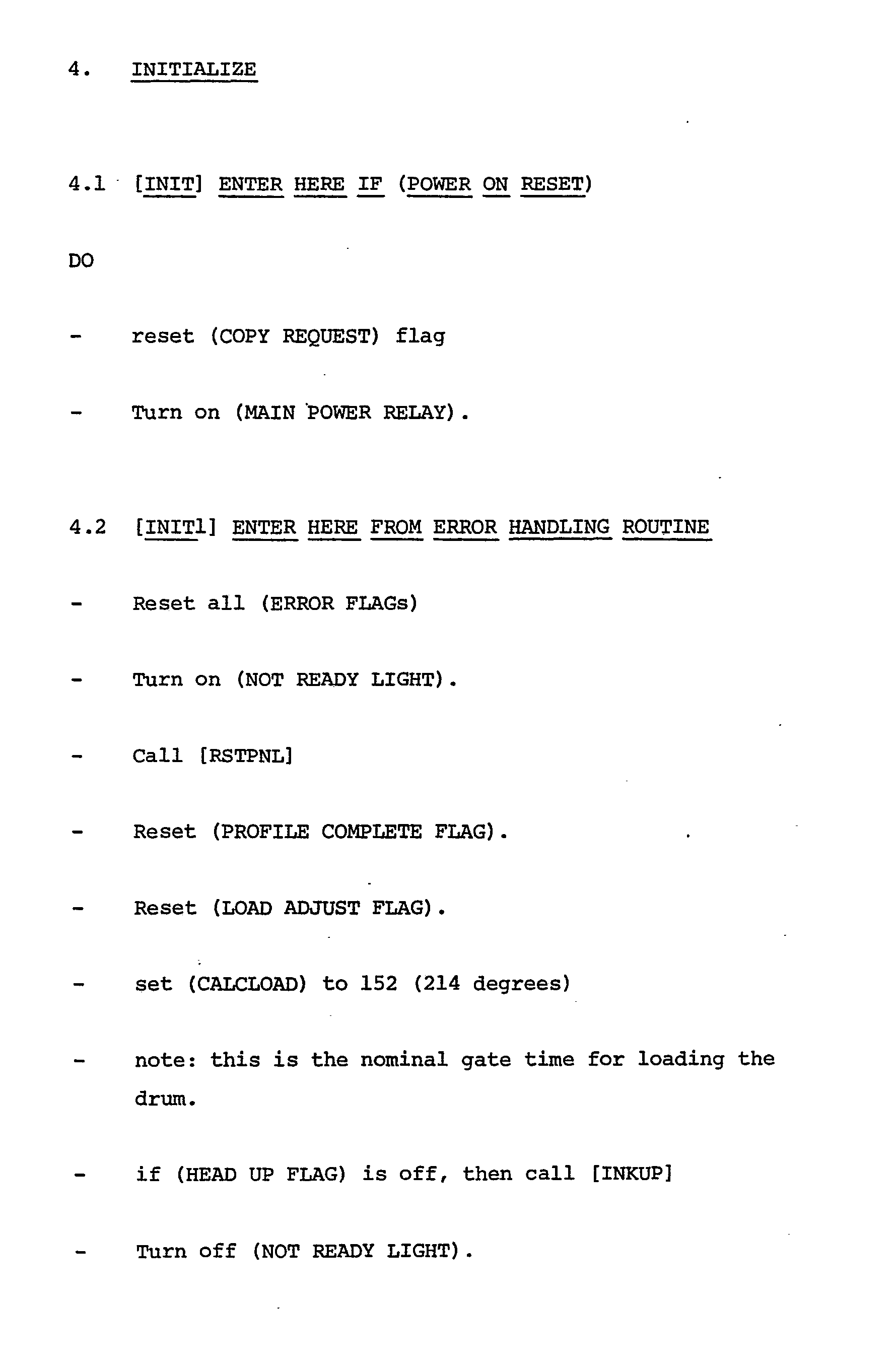


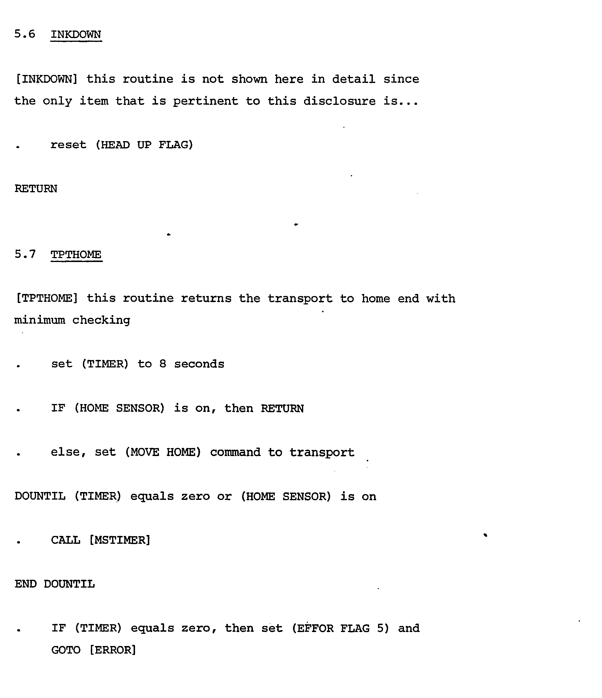


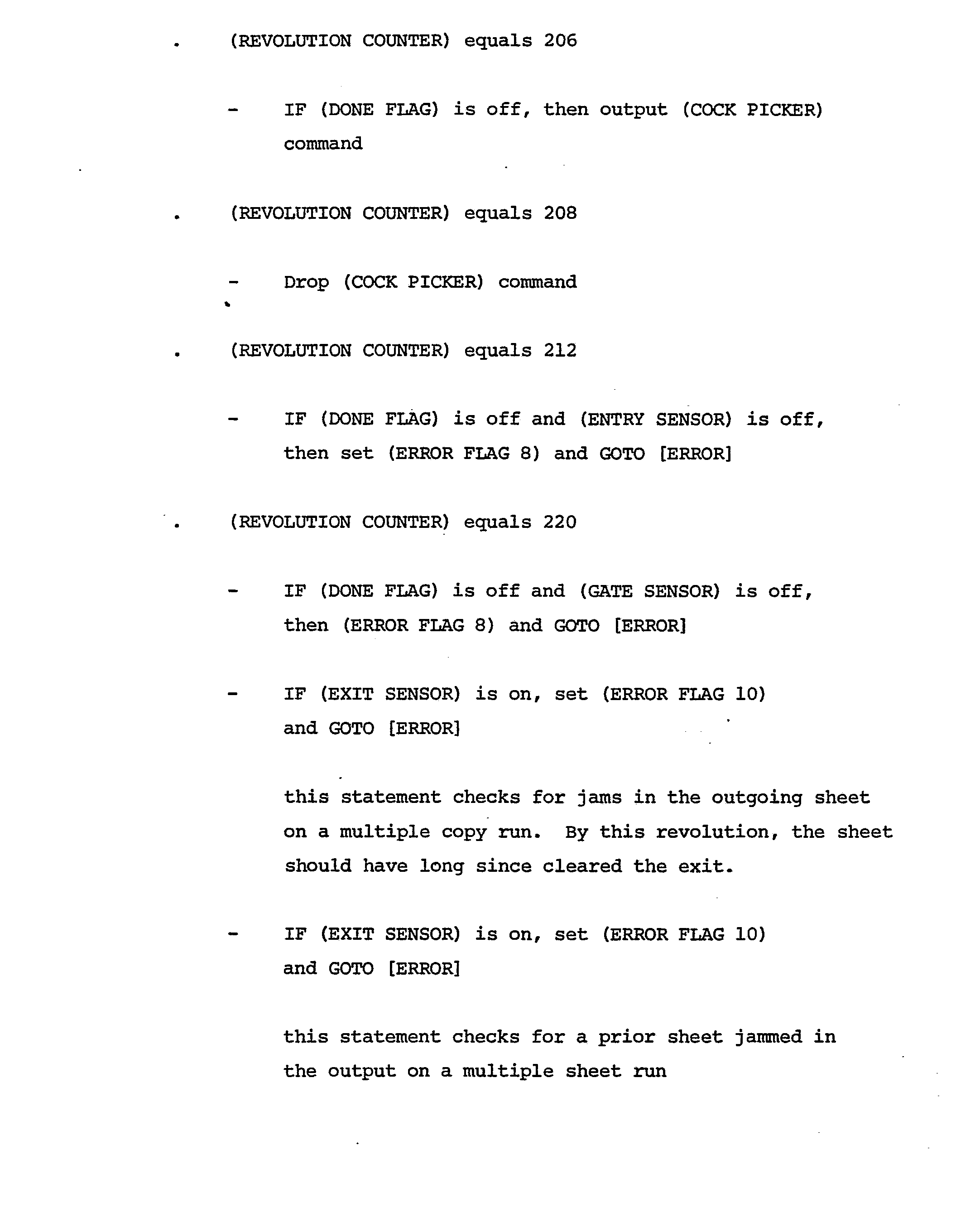


Claims (10)
Priority Applications (1)
| Application Number | Priority Date | Filing Date | Title |
|---|---|---|---|
| AT80101466T ATE20216T1 (en) | 1979-04-30 | 1980-03-20 | PROCESSOR CONTROLLED PRINTING DEVICE AND HOW IT WORKS. |
Applications Claiming Priority (2)
| Application Number | Priority Date | Filing Date | Title |
|---|---|---|---|
| US06/034,841 US4275968A (en) | 1979-04-30 | 1979-04-30 | System for controlling and sequencing a printer |
| US34841 | 1993-03-19 |
Publications (3)
| Publication Number | Publication Date |
|---|---|
| EP0019694A2 true EP0019694A2 (en) | 1980-12-10 |
| EP0019694A3 EP0019694A3 (en) | 1982-08-11 |
| EP0019694B1 EP0019694B1 (en) | 1986-06-04 |
Family
ID=21878939
Family Applications (1)
| Application Number | Title | Priority Date | Filing Date |
|---|---|---|---|
| EP80101466A Expired EP0019694B1 (en) | 1979-04-30 | 1980-03-20 | Processor controlled printing device and operation thereof |
Country Status (12)
| Country | Link |
|---|---|
| US (1) | US4275968A (en) |
| EP (1) | EP0019694B1 (en) |
| JP (1) | JPS608235B2 (en) |
| AT (1) | ATE20216T1 (en) |
| AU (1) | AU540322B2 (en) |
| BR (1) | BR8002076A (en) |
| CA (1) | CA1143857A (en) |
| DE (1) | DE3071627D1 (en) |
| DK (1) | DK185280A (en) |
| ES (1) | ES491020A0 (en) |
| FI (1) | FI801324A7 (en) |
| NO (1) | NO801055L (en) |
Cited By (1)
| Publication number | Priority date | Publication date | Assignee | Title |
|---|---|---|---|---|
| US4538933A (en) * | 1982-09-10 | 1985-09-03 | Brother Kogyo Kabushiki Kaisha | Paper feeding apparatus in a printer |
Families Citing this family (16)
| Publication number | Priority date | Publication date | Assignee | Title |
|---|---|---|---|---|
| US4455080A (en) * | 1980-11-04 | 1984-06-19 | Minolta Camera Kabushiki Kaisha | Copying apparatus equipped with control device |
| US4482240A (en) * | 1981-06-24 | 1984-11-13 | Canon Kabushiki Kaisha | Electrophotographic process utilizing electrostatic separation and apparatus therefor |
| CH654256A5 (en) * | 1983-06-03 | 1986-02-14 | Hermes Precisa International | SHEET FEEDING DEVICE FOR PRINTER OR WRITING MACHINE. |
| JPS6233662A (en) * | 1985-08-08 | 1987-02-13 | Alps Electric Co Ltd | Control system of motor for printer |
| US4792249A (en) * | 1985-09-20 | 1988-12-20 | Creative Associates Limited Partnership | Vacuum paper transport system for printer |
| US4933772A (en) * | 1985-10-07 | 1990-06-12 | Minolta Camera Kabushiki Kaisha | Electrophotographic printer with improved timing arrangements |
| WO1988003301A1 (en) * | 1986-10-31 | 1988-05-05 | Takenaka Engineering Co., Ltd. | Passive infrared burglar sensor equipped with visual field interruption monitor mechanism |
| US4854756A (en) * | 1987-08-03 | 1989-08-08 | Printronix, Inc. | Adaptive print hammer timing system |
| US5018716A (en) * | 1988-03-11 | 1991-05-28 | Canon Kabushiki Kaisha | Sheet transporting apparatus with control means |
| US5619240A (en) * | 1995-01-31 | 1997-04-08 | Tektronix, Inc. | Printer media path sensing apparatus |
| US5980139A (en) * | 1998-04-24 | 1999-11-09 | Lexmark International, Inc. | Method of speed control for imaging system including printers with intelligent options |
| US6334677B1 (en) * | 1998-12-11 | 2002-01-01 | Eastman Kodak Company | Format flexible ink jet printing having efficient receiver usage |
| US6640157B2 (en) | 2002-02-11 | 2003-10-28 | Lexmark International, Inc. | Method for operating a media feed motor of a printer |
| JP2005077469A (en) * | 2003-08-28 | 2005-03-24 | Ricoh Co Ltd | Image forming apparatus |
| JP2011161649A (en) * | 2010-02-04 | 2011-08-25 | Ricoh Co Ltd | Image forming apparatus, servo control device, and program |
| US8510170B2 (en) * | 2010-12-22 | 2013-08-13 | Toshiba Global Commerce Solutions Holdings Corporation | Powering a point of sale printer and coupon printer from a shared power supply |
Family Cites Families (14)
| Publication number | Priority date | Publication date | Assignee | Title |
|---|---|---|---|---|
| US3935434A (en) * | 1963-03-04 | 1976-01-27 | Technicolor, Inc. | Printer control |
| US3887796A (en) * | 1964-10-26 | 1975-06-03 | California Computer Products | Digital incremental control system |
| US3774056A (en) * | 1971-04-29 | 1973-11-20 | Design And Manuf Corp | Digital electronic control circuit for cyclically operable appliances and the like |
| US3741640A (en) * | 1971-10-21 | 1973-06-26 | Eastman Kodak Co | Sequencer device for controlling web replacement in electrophotographic apparatus |
| US3784190A (en) * | 1971-12-27 | 1974-01-08 | Ibm | Sheet removing apparatus |
| US3843114A (en) * | 1972-03-11 | 1974-10-22 | Shibaura Electric Co Ltd | Apparatus for automatic takeup and release of sheets |
| US3768904A (en) * | 1972-05-17 | 1973-10-30 | Xerox Corp | Printing apparatus including registration control |
| US4050564A (en) * | 1973-11-23 | 1977-09-27 | International Business Machines Corporation | Electronic control for optimizing carrier turnaround in printing apparatus |
| US3944360A (en) * | 1974-08-12 | 1976-03-16 | Xerox Corporation | Programmable controller for controlling reproduction machines |
| US3940210A (en) * | 1974-08-12 | 1976-02-24 | Xerox Corporation | Programmable controller for controlling reproduction machines |
| US3922587A (en) * | 1974-10-25 | 1975-11-25 | Rca Corp | Digital feedback relay controller |
| FR2339202A1 (en) * | 1976-01-26 | 1977-08-19 | Penet Pierre | CONTROL UNIT FOR AN ELECTRIC OR HYDRAULIC BODY WITH PERIODIC OPERATION AND DEVICE FOR MEASURING THE FLUID FLOW INCORPORATING SUCH ASSEMBLY |
| FR2379458A1 (en) * | 1977-02-07 | 1978-09-01 | Ibm | LEAF TRAINING DEVICE |
| US4147967A (en) * | 1977-11-10 | 1979-04-03 | Ncr Corporation | Apparatus and method for controlling the velocity of a moveable member |
-
1979
- 1979-04-30 US US06/034,841 patent/US4275968A/en not_active Expired - Lifetime
-
1980
- 1980-02-05 CA CA000345123A patent/CA1143857A/en not_active Expired
- 1980-03-14 AU AU56453/80A patent/AU540322B2/en not_active Ceased
- 1980-03-20 DE DE8080101466T patent/DE3071627D1/en not_active Expired
- 1980-03-20 AT AT80101466T patent/ATE20216T1/en not_active IP Right Cessation
- 1980-03-20 EP EP80101466A patent/EP0019694B1/en not_active Expired
- 1980-04-02 BR BR8002076A patent/BR8002076A/en unknown
- 1980-04-11 NO NO801055A patent/NO801055L/en unknown
- 1980-04-18 JP JP55050520A patent/JPS608235B2/en not_active Expired
- 1980-04-24 FI FI801324A patent/FI801324A7/en not_active Application Discontinuation
- 1980-04-29 ES ES491020A patent/ES491020A0/en active Granted
- 1980-04-29 DK DK185280A patent/DK185280A/en not_active Application Discontinuation
Cited By (1)
| Publication number | Priority date | Publication date | Assignee | Title |
|---|---|---|---|---|
| US4538933A (en) * | 1982-09-10 | 1985-09-03 | Brother Kogyo Kabushiki Kaisha | Paper feeding apparatus in a printer |
Also Published As
| Publication number | Publication date |
|---|---|
| JPS55146583A (en) | 1980-11-14 |
| DE3071627D1 (en) | 1986-07-10 |
| ES8102917A1 (en) | 1981-02-16 |
| NO801055L (en) | 1980-10-31 |
| EP0019694A3 (en) | 1982-08-11 |
| EP0019694B1 (en) | 1986-06-04 |
| JPS608235B2 (en) | 1985-03-01 |
| AU5645380A (en) | 1980-11-06 |
| US4275968A (en) | 1981-06-30 |
| AU540322B2 (en) | 1984-11-15 |
| BR8002076A (en) | 1980-11-25 |
| ATE20216T1 (en) | 1986-06-15 |
| FI801324A7 (en) | 1980-10-31 |
| DK185280A (en) | 1980-10-31 |
| CA1143857A (en) | 1983-03-29 |
| ES491020A0 (en) | 1981-02-16 |
Similar Documents
| Publication | Publication Date | Title |
|---|---|---|
| EP0019694A2 (en) | Processor controlled printing device and operation thereof | |
| US4469026A (en) | Method and apparatus for controlling drying and detaching of printed material | |
| EP0025878B1 (en) | Apparatus and method for drying ink printed on a print medium in a printing system | |
| US3994487A (en) | Sheet handling apparatus | |
| US5921690A (en) | Discharged-sheet stacking device, and image forming apparatus including the same | |
| EP0214549A2 (en) | Printing press and control method of plate feeding operation of the same | |
| EP0228789B1 (en) | Process and apparatus for setting a cut printing sheet | |
| JPS5813460B2 (en) | Sheet multiple offset group sorting and feeding device | |
| JP3691618B2 (en) | Tape printer | |
| EP1901237B1 (en) | Method and system for high speed digital metering using low velocity print technology | |
| EP0202129A1 (en) | Feeding apparatus for printing medium | |
| CA1284467C (en) | Lining method and apparatus for printer | |
| EP0295969A1 (en) | Paper feed control system for printers | |
| JP2694691B2 (en) | Printer device | |
| JPH0110711Y2 (en) | ||
| JP3504106B2 (en) | Print media transport device | |
| JPH0263871A (en) | Sheet processing system | |
| JP2657919B2 (en) | Printer device | |
| JP2020023056A (en) | Image recording device | |
| JPS63162265A (en) | printer | |
| JPH07257799A (en) | Printer, and sheet distributing method therefor | |
| JPS6189068A (en) | Printer control device with automatic paper feeder | |
| JPH0664257A (en) | Printer control method | |
| JPH11165926A (en) | Machine glazed paper feeder | |
| JPH02132022A (en) | Sheet storage container conveyance device |
Legal Events
| Date | Code | Title | Description |
|---|---|---|---|
| PUAI | Public reference made under article 153(3) epc to a published international application that has entered the european phase |
Free format text: ORIGINAL CODE: 0009012 |
|
| AK | Designated contracting states |
Designated state(s): AT BE CH DE FR GB IT NL SE |
|
| 17P | Request for examination filed |
Effective date: 19810108 |
|
| PUAL | Search report despatched |
Free format text: ORIGINAL CODE: 0009013 |
|
| AK | Designated contracting states |
Designated state(s): AT BE CH DE FR GB IT NL SE |
|
| GRAA | (expected) grant |
Free format text: ORIGINAL CODE: 0009210 |
|
| AK | Designated contracting states |
Kind code of ref document: B1 Designated state(s): AT BE CH DE FR GB IT NL SE |
|
| PG25 | Lapsed in a contracting state [announced via postgrant information from national office to epo] |
Ref country code: NL Effective date: 19860604 Ref country code: AT Effective date: 19860604 |
|
| REF | Corresponds to: |
Ref document number: 20216 Country of ref document: AT Date of ref document: 19860615 Kind code of ref document: T |
|
| PG25 | Lapsed in a contracting state [announced via postgrant information from national office to epo] |
Ref country code: SE Effective date: 19860630 |
|
| ITF | It: translation for a ep patent filed | ||
| REF | Corresponds to: |
Ref document number: 3071627 Country of ref document: DE Date of ref document: 19860710 |
|
| ET | Fr: translation filed | ||
| NLV1 | Nl: lapsed or annulled due to failure to fulfill the requirements of art. 29p and 29m of the patents act | ||
| PLBE | No opposition filed within time limit |
Free format text: ORIGINAL CODE: 0009261 |
|
| STAA | Information on the status of an ep patent application or granted ep patent |
Free format text: STATUS: NO OPPOSITION FILED WITHIN TIME LIMIT |
|
| 26N | No opposition filed | ||
| PGFP | Annual fee paid to national office [announced via postgrant information from national office to epo] |
Ref country code: BE Payment date: 19910114 Year of fee payment: 12 |
|
| PGFP | Annual fee paid to national office [announced via postgrant information from national office to epo] |
Ref country code: GB Payment date: 19910220 Year of fee payment: 12 |
|
| PGFP | Annual fee paid to national office [announced via postgrant information from national office to epo] |
Ref country code: FR Payment date: 19910225 Year of fee payment: 12 |
|
| PGFP | Annual fee paid to national office [announced via postgrant information from national office to epo] |
Ref country code: DE Payment date: 19910323 Year of fee payment: 12 |
|
| ITTA | It: last paid annual fee | ||
| PGFP | Annual fee paid to national office [announced via postgrant information from national office to epo] |
Ref country code: CH Payment date: 19910625 Year of fee payment: 12 |
|
| PG25 | Lapsed in a contracting state [announced via postgrant information from national office to epo] |
Ref country code: GB Effective date: 19920320 |
|
| PG25 | Lapsed in a contracting state [announced via postgrant information from national office to epo] |
Ref country code: CH Effective date: 19920331 Ref country code: BE Effective date: 19920331 |
|
| BERE | Be: lapsed |
Owner name: INTERNATIONAL BUSINESS MACHINES CORP. Effective date: 19920331 |
|
| GBPC | Gb: european patent ceased through non-payment of renewal fee | ||
| PG25 | Lapsed in a contracting state [announced via postgrant information from national office to epo] |
Ref country code: FR Effective date: 19921130 |
|
| REG | Reference to a national code |
Ref country code: CH Ref legal event code: PL |
|
| PG25 | Lapsed in a contracting state [announced via postgrant information from national office to epo] |
Ref country code: DE Effective date: 19921201 |
|
| REG | Reference to a national code |
Ref country code: FR Ref legal event code: ST |