EP0019901A1 - Vorrichtung zum Halten eines Werkstückes während der moderierten Behandlungsvorgänge - Google Patents
Vorrichtung zum Halten eines Werkstückes während der moderierten Behandlungsvorgänge Download PDFInfo
- Publication number
- EP0019901A1 EP0019901A1 EP80102949A EP80102949A EP0019901A1 EP 0019901 A1 EP0019901 A1 EP 0019901A1 EP 80102949 A EP80102949 A EP 80102949A EP 80102949 A EP80102949 A EP 80102949A EP 0019901 A1 EP0019901 A1 EP 0019901A1
- Authority
- EP
- European Patent Office
- Prior art keywords
- vise
- gripping
- workpiece
- bowl
- aperture
- Prior art date
- Legal status (The legal status is an assumption and is not a legal conclusion. Google has not performed a legal analysis and makes no representation as to the accuracy of the status listed.)
- Withdrawn
Links
Images



Classifications
-
- B—PERFORMING OPERATIONS; TRANSPORTING
- B25—HAND TOOLS; PORTABLE POWER-DRIVEN TOOLS; MANIPULATORS
- B25B—TOOLS OR BENCH DEVICES NOT OTHERWISE PROVIDED FOR, FOR FASTENING, CONNECTING, DISENGAGING, OR HOLDING
- B25B1/00—Vices
- B25B1/22—Arrangements for turning or tilting vices
Definitions
- This invention relates generally to apparatus for supporting a workpiece.
- the invention relates more particularly to an improved vise for supporting a workpiece which is subjected to relatively moderate to light working operations.
- Bench top vises are known for gripping and supporting a workpiece during a working operation on the workpiece. These vises generally include a vise body having a pair of gripping jaw members which are forced into engagement with, and sandwich, a workpiece therebetween. Relative motion between the jaw members for gripping or releasing a workpiece is provided by the rotary motion of a lever actuated screw which engages internally threaded segments of the jaw members.
- a means is provided for mounting the vise body to a table surface or bench top for rigidly securing the vise during a working operation. Typical mounting means comprise bolts, lag screws and clamps.
- a working operation is facilitated by rotating the vise body and the gripped workpiece in order to present the workpiece at a more convenient attitude.
- a means has been provided for rotating the vise about various axes.
- a vise is also often required to grip an elongated workpiece such as a pipe. Both the construction of the vise and its mounting to a workbench can interfere with such use.
- These limitations have been circumvented by off center gripping of the workpiece and mounting of the vise.
- the jaw actuating screw is generally positioned at a centrally located position beneath the jaws thus necessitating positioning of an elongated workpiece at an off center location between the jaws so as to by-pass the transversely extending screw.
- the vise body must also be mounted to provide bench overhangfor enabling a non- interferring extension of an elongated workpiece.
- the working operations to which a vise supported workpiece are subjected include, for example, forming and shaping by pounding, hammering, filing, grinding, shearing, heating, welding, soldering, etc.
- the bench top vise is ruggedly constructed , it is formed of solid metal, it has considerable weight and is relatively costly.
- the aforementioned vise provides satisfactory gripping of workpieces at a workbench, their size, weight and configuration do not lend to ready portability of the vise and such a vise is considered to be stationary and not convenient to movement from work place to work place.
- Another object of the invention is to provide an improved vise for supporting a workpiece during relatively moderate to light working operations.
- Another object of the invention is to provide an improved vise for stationary or portable use, which is of relatively light weight and which can be economically fabricated.
- Another object of the invention is to provide a portable vise for supporting a workpiece during relatively moderate to light working operations and which has an enhanced gripping jaw spacing for supporting relatively large workpieces.
- Still another object of the invention is to provide a portable vise for supporting an elongated workpiece during relatively moderate to light working operations and having an improved arrangement for providing clearance of a vertically supported elongated workpiece.
- Another ком ⁇ онент of the invention is to provide an improved portable vise having means for varying an angle between gripping jaw members of the vise.
- Another object of the invention is to provide a portable vise which can be used free standing and which is readily mounted to and demounted from a worktable.
- a further object of the invention is to provide an improved vise for hobby use.
- a support means for first and second workpiece- gripping jaw members including a support body having a freme member and an integrally formed bowl shaped member.
- the frame member which extends in a pricipal plane includes an aperture and provides a support surface for the jaw members for movement thereof in a direction parallel to the principal plane and adjacent the aperture.
- the bowl shaped member extends transversely to the principal plane and communicates with the aperture.
- the support means further includes a base body having a cavity formed therein. The cavity is adapted for receiving and seating a bottom segment of the bowl member, and, a curved surface of the cavity engages a curved surface of the bowl member for sliding engagement therebetween.
- a restraining means is provided which captivates the support body in the cavity and alternatively enables sliding movement of the bowl member of maintains the bowl member at a preselected orientation.
- a means is provided for mounting the jaw members to the frame member for varying the relative spacing therebetween for gripping a workpiece.
- the support means is formed of a relatively light and relatively economic material and preferably a polymer plastic.
- the vise arrangement is advantageous in that it is fabricated of a relatively lightweight, relatively low cost material yet is adapted to sustain relatively moderate to light working forces which are impressed on a gripped workpiece and which are distributed form the workpiece through the frame member, the bowl member, and the base body to a support surface for the vise.
- the support body provides for a limited extension of an elongated workpiece through the frame aperture and into the anterior of the bowl.
- the gripped workpiece can thereby be centrally orientated on the vise.
- the frame member provides a means for supporting the jaw members adjacent a surface thereof, and enables the jaw members to be relatively widely spaced along a length of the frame member for supporting a relatively large workpiece.
- a means for varying the relative spacing between the jaw members is adapted to provide for positioning of faces of the jaw members in an anti-parallel attitude thereby enabling gripping of a wedge shaped or a tapered workpiece.
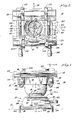
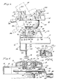
- a vise 16 of the invention is shown supported on a surface 17 of a workbench or a support table.
- the vise 16 includes first and second workpiece gripping jaw members 18 and 20 and a means for supporting these members.
- the vise support means comprises a support body 22 and a base body 24.
- Support body 22 comprises an integrally formed frame member 26 and an integrally formed bowl shaped member 28.
- the jaw members 18 and 20, the support body 22 and the base body 24 are fabricated of a relatively lightweight economical material.
- One such material is a polymer plastic.
- a preferable polymer plastic material is a structural foam.
- the frame member 26 includes a surface segment 29, a peripheral skirt segment 30 and has a length 31 and a - width 32.
- the surface segment 29 includes parallel aligned segments 36 and 38 each having elongated slots 40 and 42 formed therein.
- An aperture 52 (Fig.2) is provided in the surface and extends in the direction of a plane defined by the mutually perpendicular axes 56 and 57 (Fig.2).
- the first jaw member 18 is stationary and is mounted to the surface 36 and 38 as indicated in more detail hereinafter.
- the second jaw member 20 extends between the surfaces 36 and 38, and, as indicated hereinafter, is advanced toward and retracted from the stationary member 18 for respectively gripping and releasing a workpiece 60 as shown in Fig. 5 or an workpiece 61 as shown in Fig. 6.
- the bowl member 28 communicates with the aperture 52 of the frame member.
- the bowl member 28 which has a longitudinal axis 62 extends from the aperture 52 of the frame member in the direction of its longitudinal axis.
- the bowl member 28 includes a curved spherical segment 64 (Fig. 4) shown to be a thin walled hollow hemisphere and having a curved surface segment 66 located at a bottom section 67 of the member.
- the bowl member 28 has a depth extending in the direction of its longitudinal axis 62 which enables extension of an elongated workpiece into an interior of the member.
- the bowl member can comprise a hollow hemispherical body or it includes an extension segment such as the integral cylindrical segment 69 (Fig. 4) which is positioned between the spherical segment 64 and the aperture 52.
- a cut-out 70 is formed in the spherical segment through which a component of a restraining means extends, as is indicated in greater detail hereinafter.
- the base body 24 includes a plurality of upstanding wall segments 74, 76, 78 (Fig. 1) and 80 (Fig. 7) which provide an elevated platform surface 82 in which a depending cavity 84 is formed.
- the cavity 84 includes a curved surface 86 which conforms with the curvature of the surface 66 of the bowl segment 64. Cavity 84 is thus adapted to receive and seat the bowl member 28 for sliding engagement between the bowl and base body surfaces.
- a plurality of feet 89 are mounted to the bottom surface for spacing the base body from the table surface 17. These feet made of a polymer for example provide against movement and slippage of the vise and avoid scratching of a finished surface 17.
- a restraining means is provided for captivating the bowl member 28 in the cavity 84 and for alternatively enabling sliding movement between the surfaces 66 and 86 or maintaining the bowl member 28 at a preselected orientation.
- the restraining means includes a lock body 120 (Fig. 7) shaped as a spherical segment which is positioned in the bowl member 28.
- a spherically curved surface 124 conforms in surface configuration with a spherically curved surface 125 of the interior of the bowl 28.
- Body 120 includes a hub segment 122 and a key shaped boss 123 extending axially from the hub segment 122 through the cutout 70 and into the base body 24.
- a hexagonal shaped aperture 130 is formed in the hub segment 22 and a cylindrical shaped bore 131 of reduced diameter is formed in the hub and in the boss 123.
- a rod 132 having a hexagonal head engages the hexagonal aperture 130 and rotation thereof is inhibited.
- the rod 132 extends through the aperture 130 and the bore 131.
- the restraining means further includes a cylindrically shaped base body hub 133 integrally formed on the base body and through which a key shaped aperture 134 extends.
- the key shaped boss 123 of body 120 engages aperture 134 and inhibits rotary movement of the body 120.
- An annular array of raised ramp shaped segments 140, 142, 144 and 146 are integrally formed on a surface 136 of hub 133.
- a locking lever 148 is provided having a surface 150, an aperture 152 formed therein, and an annular array of ramp shaped segments 154, 156, 158 and 160 which are integrally formed with the lever 148 and extend from the surface 150.
- the ramp segments are arrayed for providing that each ramp segment increases in height in a predetermined direction ' as, for example, in a counter-clockwise direction as shown in Figure 10.
- the lever 148 is maintained in engagement with the surface 136 of the base body hub 133 by the screw 132 which extends through the aperture 152 in the lever arm 148, a washer 164 and a locking nut 166.
- the lock lever 148 includes a lever arm segment 162 which extends through the aperture 90 formed in the base body wall.
- this aperture includes a ratchet shaped segment 167 extending to a notch 168.
- the ramp segments 140, 142, 144 and 146 are forced into engagement with the corresponding ramp segments 154, 156 158 and 160, thereby forcing the screw 132 to advance in an axial direction toward the base body 24.
- the effect of movement is determined by the relative positioning of ramp segments 140-146 and 154-160.
- the lever arm is advanced about 30° to'60 0 to establish interference.
- the captivating spherical body 120 then exerts a force on the spherical segment 64 which is positioned between this body and the cavity surface 86.
- the bowl member 28 is advantageously adjustable in the cavity and has substantial freedom of movement in order to present the workpiece at a desired attitude.
- the extent of reorientation and movement of the bowl member 28 in the cavity about three axes is determined by the size and configuration of the cutout 70.
- the cutout 70 is configured and sized to provide on the one hand a substantial degree of unlimited movement, and, on the other hand, to provide a bowl surface segment 66 having an area sufficiently large to assure mechanical integrity of the bowl in supporting the bowl member and for enabling restraint of the same upon the application of a sandwiching force by the spherical body 120.
- the restraining arrangement is advantageous in that the spherical configuration of the body 120 applies a restraining force across a gap of the cutout and contributes to the rigidity of the bowl member in the area of the cutout.
- the cutout 70 is at least coextensive with the axis 218 (Fig. 7) thereby enabling the bowl member 28 to rotate 360° about this axis.
- the cutout is formed for providing that the bowl member may be rotated an angular distance ( ⁇ ) about an axis 222 (Fig. 7). Since the bowl member 28 can be rotated 360° about an axis 218, the angular rotation (oC) is effectively doubled.Orientation about the axis 222 is shown in Figure 5.
- the cutout is also shaped to enable rotation for an angular distance (6) (Fig. 4) 220.
- Various orientations about the axis 220 are illustrated in Figures 1 and 11.
- the size and configuration of the cutout can be varied to suit particular needs. It has been found that the angles ( ⁇ ) and (e) can equal 40° and 20 0 respectively while providing sufficient structural integrity for a hemispherical segment 64 formed of a structural polymer foam having a radius of 51 mm and a wall thickness of 5 mm.
- a quick connect and disconnect mounting means comprises a clamp 92 (Fig. 5, 11 and 15) which is provided for mounting and demounting the base body 24 to the surface 17 of a worktable or bench top.
- the clamp 92 comprises a formed wire body having horizontal segments 94 and 96 which extend over an upper surface of the work support table, horizontal segments 98 and 100 which extend below a lower surface of the worktable, vertical segments 102 and 104, and segments 106 and 108 for engaging surfaces 109 and 110 in the base body 24.
- a plate 112 is provided and extends between the lower horizontal segments 98 and 100.
- An aperture 113 is formed in the plate and a screw 114 engages and extends through the aperture.
- the screw 114 includes a knob 116 and a tip 118 mounted at opposite ends of the screw for respectively rotating the screw and for engaging the lower section of the worktable.
- the vise 16 can be screw mounted to a table by screws 115 extending through apertures 117 in the segments 106 and 108 or it can be utilized freestanding without use of any mounting members.
- the first gripping member 18 comprises an elongated stationary member having a lower, flat surface 171 engaging support surfaces 36 and 38 (Fig. 2) and upper angled surfaces 173. This member is mounted to the frame by screws 172 and 174.
- the second jaw member 20 is transported by means including first and second, elongated, rotatably mounted screws 176 and 178.
- Apertures 180 and 182 (Fig. 3) formed in the frame member 26 provide for support of the screws at one end thereof.
- the arrangement of the screw support and jaw member transport is the same for each of the screws 176 and 178.
- the following description, which is applicable to the screw 176, is equally applicable to screw 178 and similar components are provided for supporting the screw 178.
- a distal segment of the screw 176 extends through the aperture 180 (Fig.
- a rotatable knob 186 is pressed on and captivated by a lever segment 183 of the crank arm.
- a plate or washer 188 is positioned on the screw adjacent a wall segment of the frame member and a pin 190 extends through a transverse bore 191 in the screw for inhibiting longitudinal movement of the screw through the aperture.
- the pin and washer as well as a surface 193 on the crank arm inhibits movement of the screw 176 in an axial direction.
- the screw 176 is supported at another location along its length and is mechanically coupled to the transported jaw 20 by a travel body or pivot nut 192.
- the body 192 includes an internally threaded bore 198 which is engaged by the screw 176.
- a shoulder 200 is formed on the body 192 and an aperture 201 is formed therein.
- a screw 202 extends through this aperture and engages the gripping member 20 in a bore 205.
- the screw 202 while engaging the gripping member 20 includes a flat head segment 203 and is freely rotatable in the aperture 201.
- the screw 176 rotates causing movement of the travel body 192 in an axial direction in accordance with the direction of the rotation of the crank.
- Screw 202 extends through the . elongated slot 42 formed in the frame member 26 surface 38 and causes jaw member 20 to travel therewith.
- a similar supportable arrangement is provided near an opposite end of the member 20.
- the jaw member 20 By rotating cranks 184 and crank 207, the jaw member 20 is advanced and retracted relative to the stationary member 18 with jaw face 209 and 211 (Fig. 6) thereof parallel.
- the jaw faces 209 and 211 are positioned anti-parallel. This is advantageous in that tapered and wedge shaped workpieces can be conveniently gripped by the jaw faces.
- the workpiece can be gripped through the use of swivel members 213 which are rotatably positioned in apertures 215 (Fig. 16, 17) formed in a jaw member.
- a swivel includes a ridge 217 and swivels on opposite jaws are employed to support a workpiece which is positioned in the ridges 217.
- the jaws 18 and 20 are spaced apart a substantial distance in the described arrangement by advancement of the transportable member 20 along the frame member surface. This spacing is further increased through the use of the swivels 213.
- the vise 16 will support a workpiece subjected to relative moderate to light pounding, hammering, etc. and during other working operations. It is particularly useful for hobby work, arts and crafts.
- the use of a support body including a frame and a bowl shaped member enables a relatively low cost, light weight vise to be fabricated of a material such as a polymer plastic yet which can support a workpiece during the application of relatively moderate or relatively light working forces on the workpiece.
- the vise can be orientated about three axes in a plurality of different attitudes and is locked at a selected orientation.
- the described arrangement further enables a limited extension of centrally gripped elongated workpieces into the interior of the bowl shaped member.
- the use of a frame member for supporting the gripping jaw members enables relatively wide spacing of these jaw members in a portable arrangement and the angularity jaw control enables gripping of tapered pieces and other non-linear arrangements.
Landscapes
- Engineering & Computer Science (AREA)
- Mechanical Engineering (AREA)
- Gripping Jigs, Holding Jigs, And Positioning Jigs (AREA)
Applications Claiming Priority (2)
| Application Number | Priority Date | Filing Date | Title |
|---|---|---|---|
| US4277879A | 1979-05-29 | 1979-05-29 | |
| US42778 | 1979-05-29 |
Publications (1)
| Publication Number | Publication Date |
|---|---|
| EP0019901A1 true EP0019901A1 (de) | 1980-12-10 |
Family
ID=21923704
Family Applications (1)
| Application Number | Title | Priority Date | Filing Date |
|---|---|---|---|
| EP80102949A Withdrawn EP0019901A1 (de) | 1979-05-29 | 1980-05-28 | Vorrichtung zum Halten eines Werkstückes während der moderierten Behandlungsvorgänge |
Country Status (4)
| Country | Link |
|---|---|
| EP (1) | EP0019901A1 (de) |
| JP (1) | JPS5621779A (de) |
| AU (1) | AU542926B2 (de) |
| CA (1) | CA1136168A (de) |
Cited By (3)
| Publication number | Priority date | Publication date | Assignee | Title |
|---|---|---|---|---|
| EP0756096A3 (de) * | 1995-07-28 | 1998-07-01 | Seiko Seiki Kabushiki Kaisha | Führungslager für krummlinige Bewegung |
| USD471070S1 (en) | 2000-03-06 | 2003-03-04 | Record Tools Limited | Clamp |
| USD473441S1 (en) | 2000-09-06 | 2003-04-22 | Record Tools Limited | Clamp |
Citations (4)
| Publication number | Priority date | Publication date | Assignee | Title |
|---|---|---|---|---|
| DE328027C (de) * | 1920-10-22 | Georg Gampe | Parallelschraubstock mit Kugelgelenkfuss | |
| CH206781A (de) * | 1938-10-11 | 1939-08-31 | Mueller Zollinger & Cie R | Maschinen-Schraubstock mit Aufspanneinrichtung. |
| GB872847A (en) * | 1957-12-05 | 1961-07-12 | Coventry Gauge & Tool Co Ltd | Compound angle work table |
| DE7212533U (de) * | 1972-06-22 | Peddinghaus P | Zwinge zum lösbaren Befestigen eines Werkzeugfußes oder des Fußes eines Werkstückhalters |
-
1980
- 1980-04-03 CA CA000349150A patent/CA1136168A/en not_active Expired
- 1980-05-28 EP EP80102949A patent/EP0019901A1/de not_active Withdrawn
- 1980-05-28 AU AU58836/80A patent/AU542926B2/en not_active Ceased
- 1980-05-29 JP JP7090280A patent/JPS5621779A/ja active Pending
Patent Citations (4)
| Publication number | Priority date | Publication date | Assignee | Title |
|---|---|---|---|---|
| DE328027C (de) * | 1920-10-22 | Georg Gampe | Parallelschraubstock mit Kugelgelenkfuss | |
| DE7212533U (de) * | 1972-06-22 | Peddinghaus P | Zwinge zum lösbaren Befestigen eines Werkzeugfußes oder des Fußes eines Werkstückhalters | |
| CH206781A (de) * | 1938-10-11 | 1939-08-31 | Mueller Zollinger & Cie R | Maschinen-Schraubstock mit Aufspanneinrichtung. |
| GB872847A (en) * | 1957-12-05 | 1961-07-12 | Coventry Gauge & Tool Co Ltd | Compound angle work table |
Cited By (3)
| Publication number | Priority date | Publication date | Assignee | Title |
|---|---|---|---|---|
| EP0756096A3 (de) * | 1995-07-28 | 1998-07-01 | Seiko Seiki Kabushiki Kaisha | Führungslager für krummlinige Bewegung |
| USD471070S1 (en) | 2000-03-06 | 2003-03-04 | Record Tools Limited | Clamp |
| USD473441S1 (en) | 2000-09-06 | 2003-04-22 | Record Tools Limited | Clamp |
Also Published As
| Publication number | Publication date |
|---|---|
| JPS5621779A (en) | 1981-02-28 |
| CA1136168A (en) | 1982-11-23 |
| AU542926B2 (en) | 1985-03-28 |
| AU5883680A (en) | 1980-12-04 |
Similar Documents
| Publication | Publication Date | Title |
|---|---|---|
| US3575405A (en) | Parallel bar clamping device | |
| US4502457A (en) | Universal multiple angle work piece holder with multiple tool conversion features | |
| US7290760B1 (en) | Rotating, positioning and tilting mechanism with cam locks | |
| CA2635614C (en) | Grinding and honing fixture with clamping jaws | |
| US7017898B2 (en) | Apparatus for securing a workpiece | |
| US4352489A (en) | Small compact lightweight portable vise suitable for use by model makers and hobbyists | |
| US4306709A (en) | Workpiece support arrangement | |
| US4619446A (en) | Adjustable support arm-type three-dimensional work bench | |
| US4804171A (en) | Workpiece holding device | |
| US4767110A (en) | Servo-clamping device | |
| US6128944A (en) | Apparatus for bending malleable metal rods | |
| US4243212A (en) | Means for restraining a swivel vise | |
| US4627604A (en) | Adjustable clamp | |
| US4248411A (en) | Apparatus for supporting a work piece | |
| US9327387B2 (en) | Integrated foot vise and wrench | |
| US4927126A (en) | Precision vise | |
| US3982740A (en) | Clamping device | |
| EP0019901A1 (de) | Vorrichtung zum Halten eines Werkstückes während der moderierten Behandlungsvorgänge | |
| US3245289A (en) | Hold-down clamp assemblage | |
| US3432934A (en) | Sine plate assembly | |
| EP0335126A2 (de) | Mehrachsige Juwelierswerkstückstütze und Positionierungsvorrichtung | |
| US4327902A (en) | Coaxial workpiece arranger for rotary work holders of contour turning machines | |
| US4265436A (en) | Workpiece support device and auxiliary support body arrangement | |
| US6032938A (en) | Carver's vise | |
| GB2189722A (en) | Clamping devices |
Legal Events
| Date | Code | Title | Description |
|---|---|---|---|
| PUAI | Public reference made under article 153(3) epc to a published international application that has entered the european phase |
Free format text: ORIGINAL CODE: 0009012 |
|
| AK | Designated contracting states |
Designated state(s): AT BE CH DE FR GB IT LU NL SE |
|
| 17P | Request for examination filed |
Effective date: 19810511 |
|
| STAA | Information on the status of an ep patent application or granted ep patent |
Free format text: STATUS: THE APPLICATION IS DEEMED TO BE WITHDRAWN |
|
| 18D | Application deemed to be withdrawn |
Effective date: 19830517 |
|
| RIN1 | Information on inventor provided before grant (corrected) |
Inventor name: WAGSTER, ROBERT PRESTON |