EP0019911B1 - Cible d'enregistrement d'images thermiques - Google Patents
Cible d'enregistrement d'images thermiques Download PDFInfo
- Publication number
- EP0019911B1 EP0019911B1 EP80102968A EP80102968A EP0019911B1 EP 0019911 B1 EP0019911 B1 EP 0019911B1 EP 80102968 A EP80102968 A EP 80102968A EP 80102968 A EP80102968 A EP 80102968A EP 0019911 B1 EP0019911 B1 EP 0019911B1
- Authority
- EP
- European Patent Office
- Prior art keywords
- image recording
- recording plate
- heat
- holes
- heat image
- Prior art date
- Legal status (The legal status is an assumption and is not a legal conclusion. Google has not performed a legal analysis and makes no representation as to the accuracy of the status listed.)
- Expired
Links
- 238000006243 chemical reaction Methods 0.000 claims description 22
- 230000005855 radiation Effects 0.000 claims description 8
- 230000000694 effects Effects 0.000 claims description 7
- 239000000463 material Substances 0.000 claims description 4
- 239000003779 heat-resistant material Substances 0.000 claims 1
- 238000001931 thermography Methods 0.000 description 17
- 230000001427 coherent effect Effects 0.000 description 4
- 230000003287 optical effect Effects 0.000 description 3
- 238000010894 electron beam technology Methods 0.000 description 2
- RTAQQCXQSZGOHL-UHFFFAOYSA-N Titanium Chemical compound [Ti] RTAQQCXQSZGOHL-UHFFFAOYSA-N 0.000 description 1
- 238000010521 absorption reaction Methods 0.000 description 1
- 230000015572 biosynthetic process Effects 0.000 description 1
- VNNRSPGTAMTISX-UHFFFAOYSA-N chromium nickel Chemical compound [Cr].[Ni] VNNRSPGTAMTISX-UHFFFAOYSA-N 0.000 description 1
- 239000013078 crystal Substances 0.000 description 1
- 238000011156 evaluation Methods 0.000 description 1
- 230000002349 favourable effect Effects 0.000 description 1
- 108010067216 glycyl-glycyl-glycine Proteins 0.000 description 1
- 238000010438 heat treatment Methods 0.000 description 1
- 238000003384 imaging method Methods 0.000 description 1
- 238000012216 screening Methods 0.000 description 1
- 230000035945 sensitivity Effects 0.000 description 1
- 230000002123 temporal effect Effects 0.000 description 1
- 230000005676 thermoelectric effect Effects 0.000 description 1
- 239000010936 titanium Substances 0.000 description 1
- 229910052719 titanium Inorganic materials 0.000 description 1
- GZXOHHPYODFEGO-UHFFFAOYSA-N triglycine sulfate Chemical compound NCC(O)=O.NCC(O)=O.NCC(O)=O.OS(O)(=O)=O GZXOHHPYODFEGO-UHFFFAOYSA-N 0.000 description 1
Images

Classifications
-
- H—ELECTRICITY
- H01—ELECTRIC ELEMENTS
- H01J—ELECTRIC DISCHARGE TUBES OR DISCHARGE LAMPS
- H01J29/00—Details of cathode-ray tubes or of electron-beam tubes of the types covered by group H01J31/00
- H01J29/02—Electrodes; Screens; Mounting, supporting, spacing or insulating thereof
- H01J29/10—Screens on or from which an image or pattern is formed, picked up, converted or stored
- H01J29/36—Photoelectric screens; Charge-storage screens
- H01J29/39—Charge-storage screens
- H01J29/45—Charge-storage screens exhibiting internal electric effects caused by electromagnetic radiation, e.g. photoconductive screen, photodielectric screen, photovoltaic screen
- H01J29/458—Charge-storage screens exhibiting internal electric effects caused by electromagnetic radiation, e.g. photoconductive screen, photodielectric screen, photovoltaic screen pyroelectrical targets; targets for infrared or ultraviolet or X-ray radiations
Definitions
- the invention relates to a thermal imaging plate, which generates a corresponding image of a locally distributed property via a physical conversion effect from the thermal radiation corresponding to a thermal image and locally distributed.
- B. a charge image via a pyroelectric effect, d.
- H. an image with locally distributed electrical charge, with a conversion layer which is screened to prevent lateral heat conduction and the associated image blur.
- Such a thermal imaging plate serves in the most general sense as a receiver of a thermal image, which is imaged on the plate via an optical device and generates a corresponding locally distributed temperature relief there by absorption and heating.
- the thermal imaging plate has a conversion layer as a carrier of the temperature relief, which translates the temperature relief into a usable property.
- this can be a locally distributed charge relief via the pyroelectric effect mentioned, but also a voltage relief with respect to a base electrode via a thermoelectric effect, or an image of locally distributed electrical resistance via a thermoresistive effect.
- electrical quantities as image content are conceivable; there may also be others such as B. a local distribution of the optical refractive index generated by the heat radiation.
- the suitable effect will be selected.
- the most common evaluation of the generated image is scanning via a sharply focused electron beam in an image pickup tube, which generates an electrical signal with a corresponding temporal progression from the image. This is then either saved or displayed as a visible image via a picture tube.
- the structure of the temperature relief through the thermal radiation imaged on the thermal imaging plate takes place according to an exponential function.
- sufficient time must be given so that the temperature relief can build up in the conversion layer and allow a sufficient intensity of the image generated by the conversion layer.
- the sharpness of the image is determined by the lateral thermal conductivity of the conversion layer or of the layers which are still present.
- the built-up local temperature differences have a tendency to flow into one another and thus reduce the image sharpness in accordance with the lateral thermal conductivity.
- the present invention is based on the problem of providing the grid of the conversion layer in such a way that sufficient mechanical stability is achieved within the conversion layer, but a separate carrier layer as a support film is not necessary.
- the holes can be designed differently. It is essential that the grid elements lying in the mesh of the line network are not completely separated from each other, i. H. that the entire reaction layer represents a coherent body with sufficient mechanical stability and breaking strength. By designing the holes, the lateral heat conduction can be throttled as desired.
- a plurality of holes are combined to form elongate slots which are separated from one another in the course of a line by remaining webs of the conversion layer.
- the holes separated from each other in this case are elongated holes.
- Another possibility is not to make this identical for each crossing point, but to make a structure in such a way that at each crossing point the network There is never a web, the slots in the course of a line each extending over at least two meshes, and the webs separating the successive slots of this line each being interrupted by a slot of a crossing line.
- a great advantage of a thermal imaging plate according to the invention proves itself in those applications where a continuous signal electrode is required for an electrical reading of the thermal image.
- This is the case, for example, with the target of a pyroelectric image recording tube, where the slotted surface side advantageously faces the incident heat radiation. Then the slots can be very narrow; there is no need to consider the scanning electron beam, which then has a continuous surface side facing it. But the slotted surface side must carry a continuous signal electrode, which is very difficult to apply in the known slitting with continuous channels.
- there is a perforated but coherent surface which can easily be covered with a coherent conductive electrode layer.
- the thermal imaging plate carries an electrically conductive layer as a signal electrode on the surface side facing the incident thermal radiation and is used as a target in an imaging tube and further preferably made of pyroelectric or thermoresistive material consists.
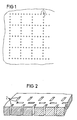
- FIG. 1 shows a section of a top view of a thermal imaging plate according to the invention made of, for example, pyroelectric triglycine sulfate single crystal.
- a grid is formed by holes 1 being drilled in the thermal imaging plate along the lines of a square mesh-forming network.
- the layer prisms in the mesh with a square collecting area represent the picture elements of the thermal imaging plate that are assigned to the individual pixels.
- the lateral conductivity present between the picture elements is set by the webs between the adjacent holes 1. This lateral heat conduction can be kept small by a large number of holes per mesh.
- FIG. 2 An arrangement according to FIG. 2 is better, where the holes are expanded into elongated holes or slots 2. Compared to the rows of holes, all but the webs remaining at the mesh knots are omitted. The lateral heat conduction between the picture elements is very low. Sufficient breaking strength can be guaranteed by the coherent laminate.
- the thermal imaging plate is sufficiently self-supporting.
- the figure shows the design of a thermal imaging plate according to the invention, where a grid of rows of slots with remaining webs is provided on the mesh knots, but where these slots 3 do not pass through the entire layer thickness. This creates a continuous sub-layer at the bottom of the slots 3.
- an electrically conductive layer 4 made of, for example, chromium-nickel or titanium and applied to the slotted surface side for heat radiation, which layer serves as a signal electrode.
- Rows of slots intersect in the manner of rows and columns and form square meshes.
- the slots 5 of the rows and the slots 6 of the columns each extend over two mesh sides. However, they overlap in such a way that a web is slit between two row slots 5 through a column slot 6 and vice versa. Due to such a structure, there is only a narrow web between adjacent grid elements for possible lateral heat conduction. Diagonal lateral heat conduction is almost completely prevented. However, the material relationship is sufficient for the mechanical strength of the entire thermal imaging plate. The formation of continuous fault lines is largely prevented.
Landscapes
- Physics & Mathematics (AREA)
- Electromagnetism (AREA)
- Radiation Pyrometers (AREA)
- Transforming Light Signals Into Electric Signals (AREA)
- Photometry And Measurement Of Optical Pulse Characteristics (AREA)
Claims (9)
Applications Claiming Priority (2)
| Application Number | Priority Date | Filing Date | Title |
|---|---|---|---|
| DE2922031 | 1979-05-30 | ||
| DE2922031A DE2922031C2 (de) | 1979-05-30 | 1979-05-30 | Wärmebildaufnahmeplatte |
Publications (2)
| Publication Number | Publication Date |
|---|---|
| EP0019911A1 EP0019911A1 (fr) | 1980-12-10 |
| EP0019911B1 true EP0019911B1 (fr) | 1982-08-25 |
Family
ID=6072078
Family Applications (1)
| Application Number | Title | Priority Date | Filing Date |
|---|---|---|---|
| EP80102968A Expired EP0019911B1 (fr) | 1979-05-30 | 1980-05-28 | Cible d'enregistrement d'images thermiques |
Country Status (4)
| Country | Link |
|---|---|
| US (1) | US4319135A (fr) |
| EP (1) | EP0019911B1 (fr) |
| JP (1) | JPS55159126A (fr) |
| DE (1) | DE2922031C2 (fr) |
Families Citing this family (4)
| Publication number | Priority date | Publication date | Assignee | Title |
|---|---|---|---|---|
| FR2492160A1 (fr) * | 1980-10-14 | 1982-04-16 | Thomson Csf | Cible pyroelectrique et tube de prise de vues muni d'une telle cible |
| JPH0743215A (ja) * | 1993-05-24 | 1995-02-14 | Mitsubishi Electric Corp | 赤外線検知素子 |
| US5485010A (en) * | 1994-01-13 | 1996-01-16 | Texas Instruments Incorporated | Thermal isolation structure for hybrid thermal imaging system |
| US5969369A (en) * | 1997-08-29 | 1999-10-19 | Fogarty; Charles M. | Infrared emissive module |
Citations (1)
| Publication number | Priority date | Publication date | Assignee | Title |
|---|---|---|---|---|
| DE2223288A1 (de) * | 1971-05-14 | 1972-11-30 | Thomson Csf | Pyroelektrische Photol?atode fuer Bildaufnahmeroehren |
Family Cites Families (4)
| Publication number | Priority date | Publication date | Assignee | Title |
|---|---|---|---|---|
| US3919555A (en) * | 1974-10-17 | 1975-11-11 | Philips Corp | Direct view infra-red to visible light converter |
| FR2345815A1 (fr) * | 1976-01-30 | 1977-10-21 | Thomson Csf | Nouveau detecteur solide de rayonnement ionisant |
| DE2835207A1 (de) * | 1977-08-18 | 1979-02-22 | Philips Nv | Pyroelektrisches vidikon mit verbessertem signal/rauschverhaeltnis |
| GB1554246A (en) * | 1977-08-20 | 1979-10-17 | English Electric Valve Co Ltd | Thermal camera tubes |
-
1979
- 1979-05-30 DE DE2922031A patent/DE2922031C2/de not_active Expired
-
1980
- 1980-05-01 US US06/145,746 patent/US4319135A/en not_active Expired - Lifetime
- 1980-05-28 EP EP80102968A patent/EP0019911B1/fr not_active Expired
- 1980-05-28 JP JP7130280A patent/JPS55159126A/ja active Pending
Patent Citations (1)
| Publication number | Priority date | Publication date | Assignee | Title |
|---|---|---|---|---|
| DE2223288A1 (de) * | 1971-05-14 | 1972-11-30 | Thomson Csf | Pyroelektrische Photol?atode fuer Bildaufnahmeroehren |
Also Published As
| Publication number | Publication date |
|---|---|
| JPS55159126A (en) | 1980-12-11 |
| DE2922031A1 (de) | 1980-12-11 |
| US4319135A (en) | 1982-03-09 |
| DE2922031C2 (de) | 1982-06-03 |
| EP0019911A1 (fr) | 1980-12-10 |
Similar Documents
| Publication | Publication Date | Title |
|---|---|---|
| DE69820040T2 (de) | Halbleiter-speicher-bauteile | |
| DE3889171T2 (de) | Bildwiedergabegerät. | |
| EP0034211B1 (fr) | Panneau de cellules solaires | |
| DE3650639T2 (de) | Aufbau eines Flüssigkristall-Mehrfarbenanzeigepaneels | |
| DE69111906T2 (de) | Verfahren zur Herstellung von Matrixen von MIM-Anordnungen und solche Matrixen enthaltende Anzeigevorrichtungen. | |
| DE3878480T2 (de) | Fluessigkristall-anzeigevorrichtung. | |
| DE1954966B2 (de) | Elektrische Speichermatrix in Kompaktbauweise | |
| DE69735990T2 (de) | Photoleitender Detektor | |
| DE2848508C2 (de) | Flüssigkristall-Anzeigetafel | |
| DE102013104644A1 (de) | Schichtelektrode für Berührungsbildschirme | |
| DE2017067B2 (de) | Pyroelektrischer Detektor | |
| DE69018618T2 (de) | Aktive flüssigkristall-punktmatrix-anzeigestruktur mit hoher auflösung. | |
| EP0019911B1 (fr) | Cible d'enregistrement d'images thermiques | |
| DE3012638A1 (de) | Glasfaserkabel mit mitteln zur ermoeglichung einer ortung | |
| DE2134467A1 (de) | Ablenkvorrichtung | |
| DE68922473T2 (de) | Wiedergabeanordnung. | |
| DE2712619A1 (de) | Schaltsystem, insbesondere eltktrographisches schreibsystem | |
| DE1622117B2 (de) | Einrichtung zur verstaerkung der intensitaet eines optischen erzeugten bildes | |
| DE69608598T2 (de) | Doppel-Gate-Flaches Bildschirm | |
| DE3216202A1 (de) | Fluessigkristall-anzeigematrix | |
| DE69224774T2 (de) | Lichtmodulationsvorrichtung und Bilderkennungsverfahren | |
| DE3436632C2 (de) | Halbleiter-Fotosensor | |
| DE69608710T2 (de) | Bildelemente | |
| DE2642194C2 (de) | Optoelektronischer Sensor nach dem Ladungsinjektions-Prinzip und Verfahren zu dessen Betrieb | |
| DE3541164A1 (de) | Flache bildwiedergabevorrichtung |
Legal Events
| Date | Code | Title | Description |
|---|---|---|---|
| PUAI | Public reference made under article 153(3) epc to a published international application that has entered the european phase |
Free format text: ORIGINAL CODE: 0009012 |
|
| AK | Designated contracting states |
Designated state(s): FR GB |
|
| 17P | Request for examination filed |
Effective date: 19810514 |
|
| GRAA | (expected) grant |
Free format text: ORIGINAL CODE: 0009210 |
|
| AK | Designated contracting states |
Designated state(s): FR GB |
|
| PGFP | Annual fee paid to national office [announced via postgrant information from national office to epo] |
Ref country code: FR Payment date: 19840524 Year of fee payment: 5 |
|
| PG25 | Lapsed in a contracting state [announced via postgrant information from national office to epo] |
Ref country code: FR Free format text: LAPSE BECAUSE OF NON-PAYMENT OF DUE FEES Effective date: 19880129 |
|
| GBPC | Gb: european patent ceased through non-payment of renewal fee | ||
| REG | Reference to a national code |
Ref country code: FR Ref legal event code: ST |
|
| PG25 | Lapsed in a contracting state [announced via postgrant information from national office to epo] |
Ref country code: GB Free format text: LAPSE BECAUSE OF NON-PAYMENT OF DUE FEES Effective date: 19881118 |
|
| PLBE | No opposition filed within time limit |
Free format text: ORIGINAL CODE: 0009261 |
|
| STAA | Information on the status of an ep patent application or granted ep patent |
Free format text: STATUS: NO OPPOSITION FILED WITHIN TIME LIMIT |