EP0019968A1 - Vorrichtung zur Ermittlung von Rissen in der wärmeisolierenden Bekleidung eines Tanks für verflüssigtes Gas - Google Patents
Vorrichtung zur Ermittlung von Rissen in der wärmeisolierenden Bekleidung eines Tanks für verflüssigtes Gas Download PDFInfo
- Publication number
- EP0019968A1 EP0019968A1 EP80200455A EP80200455A EP0019968A1 EP 0019968 A1 EP0019968 A1 EP 0019968A1 EP 80200455 A EP80200455 A EP 80200455A EP 80200455 A EP80200455 A EP 80200455A EP 0019968 A1 EP0019968 A1 EP 0019968A1
- Authority
- EP
- European Patent Office
- Prior art keywords
- fluid
- layer
- purging
- channelled
- detecting cracks
- Prior art date
- Legal status (The legal status is an assumption and is not a legal conclusion. Google has not performed a legal analysis and makes no representation as to the accuracy of the status listed.)
- Ceased
Links
- 239000012530 fluid Substances 0.000 claims abstract description 66
- 238000010926 purge Methods 0.000 claims abstract description 36
- 239000006260 foam Substances 0.000 claims description 5
- 229920005989 resin Polymers 0.000 claims description 3
- 239000011347 resin Substances 0.000 claims description 3
- 239000007789 gas Substances 0.000 abstract description 28
- IJGRMHOSHXDMSA-UHFFFAOYSA-N Atomic nitrogen Chemical compound N#N IJGRMHOSHXDMSA-UHFFFAOYSA-N 0.000 abstract description 6
- 239000007788 liquid Substances 0.000 abstract description 3
- 229910052757 nitrogen Inorganic materials 0.000 abstract description 3
- 238000011109 contamination Methods 0.000 abstract description 2
- 238000000034 method Methods 0.000 abstract 1
- 238000009827 uniform distribution Methods 0.000 abstract 1
- 238000001514 detection method Methods 0.000 description 6
- 229910000831 Steel Inorganic materials 0.000 description 3
- 239000011261 inert gas Substances 0.000 description 3
- 239000010959 steel Substances 0.000 description 3
- 230000004888 barrier function Effects 0.000 description 2
- 239000003822 epoxy resin Substances 0.000 description 2
- 229920000647 polyepoxide Polymers 0.000 description 2
- 239000004215 Carbon black (E152) Substances 0.000 description 1
- 229920005830 Polyurethane Foam Polymers 0.000 description 1
- 230000001419 dependent effect Effects 0.000 description 1
- 239000004744 fabric Substances 0.000 description 1
- 239000011521 glass Substances 0.000 description 1
- 239000003365 glass fiber Substances 0.000 description 1
- 229930195733 hydrocarbon Natural products 0.000 description 1
- 150000002430 hydrocarbons Chemical class 0.000 description 1
- 239000011810 insulating material Substances 0.000 description 1
- 239000003949 liquefied natural gas Substances 0.000 description 1
- 239000000463 material Substances 0.000 description 1
- 229920000728 polyester Polymers 0.000 description 1
- 229920001225 polyester resin Polymers 0.000 description 1
- 239000004645 polyester resin Substances 0.000 description 1
- 239000011496 polyurethane foam Substances 0.000 description 1
- 239000007787 solid Substances 0.000 description 1
- 238000005507 spraying Methods 0.000 description 1
Images

Classifications
-
- G—PHYSICS
- G01—MEASURING; TESTING
- G01M—TESTING STATIC OR DYNAMIC BALANCE OF MACHINES OR STRUCTURES; TESTING OF STRUCTURES OR APPARATUS, NOT OTHERWISE PROVIDED FOR
- G01M3/00—Investigating fluid-tightness of structures
- G01M3/02—Investigating fluid-tightness of structures by using fluid or vacuum
- G01M3/04—Investigating fluid-tightness of structures by using fluid or vacuum by detecting the presence of fluid at the leakage point
- G01M3/20—Investigating fluid-tightness of structures by using fluid or vacuum by detecting the presence of fluid at the leakage point using special tracer materials, e.g. dye, fluorescent material, radioactive material
- G01M3/22—Investigating fluid-tightness of structures by using fluid or vacuum by detecting the presence of fluid at the leakage point using special tracer materials, e.g. dye, fluorescent material, radioactive material for pipes, cables or tubes; for pipe joints or seals; for valves; for welds; for containers, e.g. radiators
- G01M3/226—Investigating fluid-tightness of structures by using fluid or vacuum by detecting the presence of fluid at the leakage point using special tracer materials, e.g. dye, fluorescent material, radioactive material for pipes, cables or tubes; for pipe joints or seals; for valves; for welds; for containers, e.g. radiators for containers, e.g. radiators
-
- F—MECHANICAL ENGINEERING; LIGHTING; HEATING; WEAPONS; BLASTING
- F17—STORING OR DISTRIBUTING GASES OR LIQUIDS
- F17C—VESSELS FOR CONTAINING OR STORING COMPRESSED, LIQUEFIED OR SOLIDIFIED GASES; FIXED-CAPACITY GAS-HOLDERS; FILLING VESSELS WITH, OR DISCHARGING FROM VESSELS, COMPRESSED, LIQUEFIED, OR SOLIDIFIED GASES
- F17C13/00—Details of vessels or of the filling or discharging of vessels
- F17C13/12—Arrangements or mounting of devices for preventing or minimising the effect of explosion ; Other safety measures
- F17C13/126—Arrangements or mounting of devices for preventing or minimising the effect of explosion ; Other safety measures for large storage containers for liquefied gas
-
- F—MECHANICAL ENGINEERING; LIGHTING; HEATING; WEAPONS; BLASTING
- F17—STORING OR DISTRIBUTING GASES OR LIQUIDS
- F17C—VESSELS FOR CONTAINING OR STORING COMPRESSED, LIQUEFIED OR SOLIDIFIED GASES; FIXED-CAPACITY GAS-HOLDERS; FILLING VESSELS WITH, OR DISCHARGING FROM VESSELS, COMPRESSED, LIQUEFIED, OR SOLIDIFIED GASES
- F17C2203/00—Vessel construction, in particular walls or details thereof
- F17C2203/03—Thermal insulations
-
- F—MECHANICAL ENGINEERING; LIGHTING; HEATING; WEAPONS; BLASTING
- F17—STORING OR DISTRIBUTING GASES OR LIQUIDS
- F17C—VESSELS FOR CONTAINING OR STORING COMPRESSED, LIQUEFIED OR SOLIDIFIED GASES; FIXED-CAPACITY GAS-HOLDERS; FILLING VESSELS WITH, OR DISCHARGING FROM VESSELS, COMPRESSED, LIQUEFIED, OR SOLIDIFIED GASES
- F17C2203/00—Vessel construction, in particular walls or details thereof
- F17C2203/06—Materials for walls or layers thereof; Properties or structures of walls or their materials
- F17C2203/0634—Materials for walls or layers thereof
- F17C2203/0658—Synthetics
- F17C2203/0663—Synthetics in form of fibers or filaments
-
- F—MECHANICAL ENGINEERING; LIGHTING; HEATING; WEAPONS; BLASTING
- F17—STORING OR DISTRIBUTING GASES OR LIQUIDS
- F17C—VESSELS FOR CONTAINING OR STORING COMPRESSED, LIQUEFIED OR SOLIDIFIED GASES; FIXED-CAPACITY GAS-HOLDERS; FILLING VESSELS WITH, OR DISCHARGING FROM VESSELS, COMPRESSED, LIQUEFIED, OR SOLIDIFIED GASES
- F17C2227/00—Transfer of fluids, i.e. method or means for transferring the fluid; Heat exchange with the fluid
- F17C2227/01—Propulsion of the fluid
- F17C2227/0128—Propulsion of the fluid with pumps or compressors
- F17C2227/0135—Pumps
-
- F—MECHANICAL ENGINEERING; LIGHTING; HEATING; WEAPONS; BLASTING
- F17—STORING OR DISTRIBUTING GASES OR LIQUIDS
- F17C—VESSELS FOR CONTAINING OR STORING COMPRESSED, LIQUEFIED OR SOLIDIFIED GASES; FIXED-CAPACITY GAS-HOLDERS; FILLING VESSELS WITH, OR DISCHARGING FROM VESSELS, COMPRESSED, LIQUEFIED, OR SOLIDIFIED GASES
- F17C2227/00—Transfer of fluids, i.e. method or means for transferring the fluid; Heat exchange with the fluid
- F17C2227/04—Methods for emptying or filling
-
- F—MECHANICAL ENGINEERING; LIGHTING; HEATING; WEAPONS; BLASTING
- F17—STORING OR DISTRIBUTING GASES OR LIQUIDS
- F17C—VESSELS FOR CONTAINING OR STORING COMPRESSED, LIQUEFIED OR SOLIDIFIED GASES; FIXED-CAPACITY GAS-HOLDERS; FILLING VESSELS WITH, OR DISCHARGING FROM VESSELS, COMPRESSED, LIQUEFIED, OR SOLIDIFIED GASES
- F17C2260/00—Purposes of gas storage and gas handling
- F17C2260/04—Reducing risks and environmental impact
Definitions
- the invention relates to a system for detecting cracks in the heat-insulating lining of a container for liquefied gas having a rigid outer shell internally provided with a heat-insulating lining.
- the rigid outer shell of such a container is made of a material, for example normal steel, which is not able to withstand the low temperature of the liquefied gas stored in the container.
- a crack develops in the heat-insulating lining of such a container, there is a risk that the contents of the container will cool down the outer shell.
- the outer shell may cool down to such a degree that, when the outer shell is made of normal steel, it would become brittle and would even deteriorate. Therefore, it is important to have a system by means of which the development of cracks in the heat-insulating lining can be detected at an early stage.
- the system for detecting cracks in the heat-insulating lining of a container for liquefied gas having a rigid outer shell internally provided with a heat-insulating lining comprises according to the invention, a channelled layer having channels so arranged that the fluid flow resistance properties of the layer are different in different directions parallel to the layer, wherein the layer is incorporated in the lining and extends along a wall area which has to be watched for the presence of a crack in the lining of said area, the layer is provided with a fluid inlet and with a fluid outlet for purging fluid, and means are present for the supply of purging fluid to the fluid inlet and for the discharge of purging fluid from the fluid outlet to a fluid analyzer, wherein the channels in the layer are so arranged along the whole area to be watched that the directional fluid flow resistance properties of the channelled layer cause the purging fluid to flow from the fluid inlet to the fluid outlet in such a manner that the purging fluid is uniformly distributed along the whole area to be watched.
- the special arrangement of the channels in the channelled layer causes the purging fluid to be uniformly distributed over the whole channelled layer, which has the advantage that the whole area to be watched for the presence of cracks in the heat-insulating lining is covered by the flow of purging fluid.
- the known crack detection systems using a channelled layer all have the disadvantage that most of the purging fluid will flow from the fluid inlet to the fluid outlet along the shortest path. In other words no, or hardly any, purging fluid tends to flow to the locations which are remote from said shortest path. In this manner only a part of the lining provided with a channelled layer can be watched effectively. Therefore, the risk that a crack is present, which cannot be traced is considerable, so that the known leak detection systems are rather unreliable.
- a heat-insulated prismatic container generally designated by reference numeral 1, comprises a rigid outer shell 2, for example made of normal steel.
- a lining 3 of heat-insulating material for example polyurethane foam, is arranged.
- This lining 3 which is preferably applied by means of a spraying method, consists of a first heat-insulating layer 3a at the high temperature side of the container and a second heat-insulating layer 3b at the low temperature side of the container.
- a channelled layer 4 is arranged between the layers 3a and 3b. Through this channelled layer a fluid, preferably an inert gas, can be passed for detecting the presence of cracks in the layer 3b.
- the channelled layer 4 comprises a number of solid obstacles or studs 5, spaced apart from each other and extending between a backing sheet 6 and a closing sheet 7, to which both ends of the studs 5 are attached.
- the studs 5 which have a length of, for example 3.5 mm, are preferably made of reinforced resin, for example a polyester resin or an epoxy resin, having for example a filling of glass ceno- spheres and glass fibres.
- the number of studs 5 per square metre is about 10,000.
- the backing sheet 6 consists, for example, of a polyester fleece.
- the closing sheet 7 must be porous to facilitate the flow of some liquefied gas stored in the container through a crack 12 in the heat-insulating layer 3b and into the channelled layer 4.
- the closing sheet 7 may, for example, be made of glass-cloth impregnated with a suitable resin, such as epoxy resin.
- a suitable resin such as epoxy resin.
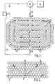
- the channelled layer 4 as shown in figure 1 is divided in sections by barriers 17, each section covering a corresponding wall area and each section having a fluid inlet 8 and a fluid outlet 9 for the purging fluid, which.is preferably an inert gas.
- the channelled layer 4 is provided with a fluid inlet 8 and a fluid outlet 9.
- Inert gas for example nitrogen serving as purging fluid, is supplied by a pump 13 and through a conduit 14 and fluid inlet 8 to the channelled layer 4.
- the gas After the gas has passed through the channelled layer 4, it is passed through the fluid outlet 9 and a conduit 15 to a gas-analyzer 10. From the gas-analyzer 10 the purging gas is recycled through a conduit 16 to the pump 13.
- the purging gas is contaminated by the liquefied gas stored in the container, this contamination, and thus the presence of a crack in the heat-insulating lining 3b, is detected by the gas-analyzer 10, which then actuates a warning device 11.
- the studs 5 are so arranged that uninterrupted passages or channels are present in direction I, and interrupted passages or channels are present in directions II and III, as indicated by the respective arrows.
- the quantity of gas flowing in direction I was about 4 times the quantity of gas flowing in direction II when said gas was supplied at location A to the channelled layer in a directbn perpendicular to the plane of said layer.
- the quantity of gas flowing in direction III had a value between the quantities of gas flowing in directions I and II.
- the uninterrupted passages or channels between the studs 5 are arranged perpendicular to the shortest path between the fluid inlet 8 and the fluid outlet 9. In the areas remote from said path the uninterrupted passages or channels extend parallel to said shortest path. As shown the directions of the uninterrupted passages or channels are obtained by selective placing of the studs 5. In figure 3, the studs 5 are shown on an enlarged scale for the sake of clarity.
- the studs as shown in the drawings have a circular cross-section. However, studs having other cross-sections can be used as well, for example studs having an octagonal cross-section.
- the invention is not restricted to a whole tank wall provided with a channelled laminate, having a single fluid inlet and a single fluid outlet.
- the tank wall it is also possible to provide only part of the tank wall with a channelled layer according to the invention, for example those parts of the wall, such as corners, which are difficult to watch with the known leak detection systems. It is also possible to provide the channelled layer with a plurality of fluid inlets and/or fluid outlets.
- a gas stream through all the layers can also be obtained by providing the bottom wall with a centrally placed fluid inlet and the top wall with a centrally placed fluid outlet.
- the purging gas will flow from the fluid inlet through the channelled layer of the bottom wall and to the periphery thereof and then through the channelled layers of all the side walls, to the periphery of the channelled layer of the top wall. Then the gas flows from the periphery of the top wall through the channelled layer of the top wall to the central outlet of the top wall.
- the barriers 17 are omitted.
- the spaces between the studs 5 can be provided with an open cell foam, if desired.
- the invention is not restricted to a channelled layer having studs or obstacles spaced apart from each other, as shown in the drawings.
- the directional channelled layer may be made of open cell foam, with a porosity varying according to the position of the foam relative to the fluid inlet and the fluid outlet, so that a porous layer is obtained having fluid flow resistance properties dependent on the direction parallel to the channelled layer.
- the obstacles may be directly bonded to the heat-insulating layer 3a.
- more than one channelled layer can be used. It is, for example, possible to use an additional channelled layer 4 in the heat-insulating layer 3a and close to the rigid outer shell 2 for detecting cracks developing in the heat-insulating layer 3a.
- the purging fluid used is preferably a gas but, if desired, it is also possible to use a purging liquid, for example a suitable liquid hydrocarbon.
Landscapes
- Engineering & Computer Science (AREA)
- Mechanical Engineering (AREA)
- General Engineering & Computer Science (AREA)
- Physics & Mathematics (AREA)
- General Physics & Mathematics (AREA)
- Filling Or Discharging Of Gas Storage Vessels (AREA)
- Examining Or Testing Airtightness (AREA)
Applications Claiming Priority (4)
| Application Number | Priority Date | Filing Date | Title |
|---|---|---|---|
| GB7918657 | 1979-05-29 | ||
| GB7918657 | 1979-05-29 | ||
| GB8005542 | 1980-02-19 | ||
| GB8005542 | 1980-02-19 |
Publications (1)
| Publication Number | Publication Date |
|---|---|
| EP0019968A1 true EP0019968A1 (de) | 1980-12-10 |
Family
ID=26271684
Family Applications (1)
| Application Number | Title | Priority Date | Filing Date |
|---|---|---|---|
| EP80200455A Ceased EP0019968A1 (de) | 1979-05-29 | 1980-05-14 | Vorrichtung zur Ermittlung von Rissen in der wärmeisolierenden Bekleidung eines Tanks für verflüssigtes Gas |
Country Status (3)
| Country | Link |
|---|---|
| EP (1) | EP0019968A1 (de) |
| ES (1) | ES8103340A1 (de) |
| NO (1) | NO801568L (de) |
Cited By (1)
| Publication number | Priority date | Publication date | Assignee | Title |
|---|---|---|---|---|
| FR2942199A1 (fr) * | 2009-02-16 | 2010-08-20 | Damien Feger | Unite de stockage et de purification d'argon embarquee sur navires methaniers |
Citations (4)
| Publication number | Priority date | Publication date | Assignee | Title |
|---|---|---|---|---|
| US3374639A (en) * | 1966-10-25 | 1968-03-26 | Mcmullen John J | Leak detection and pressure relief system for insulated liquefied gas storage tanks |
| FR2235332A1 (de) * | 1973-06-27 | 1975-01-24 | Mitsubishi Heavy Ind Ltd | |
| FR2256365A1 (de) * | 1973-12-26 | 1975-07-25 | Continental Oil Co | |
| FR2317649A1 (fr) * | 1975-07-10 | 1977-02-04 | Technigaz | Procede de controle simultane des variations de porosite de deux parois |
-
1980
- 1980-05-14 EP EP80200455A patent/EP0019968A1/de not_active Ceased
- 1980-05-27 ES ES491860A patent/ES8103340A1/es not_active Expired
- 1980-05-27 NO NO801568A patent/NO801568L/no unknown
Patent Citations (4)
| Publication number | Priority date | Publication date | Assignee | Title |
|---|---|---|---|---|
| US3374639A (en) * | 1966-10-25 | 1968-03-26 | Mcmullen John J | Leak detection and pressure relief system for insulated liquefied gas storage tanks |
| FR2235332A1 (de) * | 1973-06-27 | 1975-01-24 | Mitsubishi Heavy Ind Ltd | |
| FR2256365A1 (de) * | 1973-12-26 | 1975-07-25 | Continental Oil Co | |
| FR2317649A1 (fr) * | 1975-07-10 | 1977-02-04 | Technigaz | Procede de controle simultane des variations de porosite de deux parois |
Cited By (1)
| Publication number | Priority date | Publication date | Assignee | Title |
|---|---|---|---|---|
| FR2942199A1 (fr) * | 2009-02-16 | 2010-08-20 | Damien Feger | Unite de stockage et de purification d'argon embarquee sur navires methaniers |
Also Published As
| Publication number | Publication date |
|---|---|
| ES491860A0 (es) | 1981-02-16 |
| NO801568L (no) | 1980-12-01 |
| ES8103340A1 (es) | 1981-02-16 |
Similar Documents
| Publication | Publication Date | Title |
|---|---|---|
| US3895152A (en) | A composite cellular construction | |
| EP1763648B1 (de) | Behälter zur lagerung von flüssiggas | |
| US4696186A (en) | Storage tanks having secondary containment means | |
| KR820000334B1 (ko) | 액화개스 운송 및 저장탱크의 단열 벽 설치방법 | |
| US4739659A (en) | Double wall ribbed storage tanks | |
| US4552166A (en) | Secondary containment system and method | |
| US4715513A (en) | Toxic material storage vessel containment system | |
| US4513550A (en) | Method of building a reservoir for storing a liquid at low temperature | |
| US4524609A (en) | Storage tank systems | |
| US4523454A (en) | External jacket system as secondary containment for storage tanks | |
| US4607522A (en) | Storage tanks having secondary containment means | |
| US5054645A (en) | Storage tank systems with enhanced strength having in situ formed inner tank | |
| KR20160141780A (ko) | 부력 구조체에 수용된 밀봉, 단열된 용기 | |
| US6551024B1 (en) | System and method for detecting leaks in underground storage tank | |
| CN102667300A (zh) | 用于储存加压的气体的设备 | |
| WO2009147162A1 (en) | A cryogenic container, and method of using the same | |
| US5000342A (en) | Double walled storage tank systems with enhanced strength | |
| US4320654A (en) | System for detecting cracks in the heat-insulating lining of a container for liquefied gas | |
| EP0690816A1 (de) | Behälter | |
| JP2001500455A (ja) | 地下貯蔵タンクとその製造方法 | |
| JPH0798556B2 (ja) | ライナおよびその構築方法 | |
| KR20230035310A (ko) | 진공 패널 | |
| US5799817A (en) | Storage tank systems with encapsulated flow paths | |
| KR102955772B1 (ko) | 액화가스 저장탱크의 스프레이 쉴드 검사장치 | |
| KR830001865B1 (ko) | 액화 가스 용기의 단열내장재의 균열탐지 장치 |
Legal Events
| Date | Code | Title | Description |
|---|---|---|---|
| PUAI | Public reference made under article 153(3) epc to a published international application that has entered the european phase |
Free format text: ORIGINAL CODE: 0009012 |
|
| AK | Designated contracting states |
Designated state(s): DE FR GB IT NL SE |
|
| 17P | Request for examination filed |
Effective date: 19810512 |
|
| STAA | Information on the status of an ep patent application or granted ep patent |
Free format text: STATUS: THE APPLICATION HAS BEEN REFUSED |
|
| 18R | Application refused |
Effective date: 19831017 |
|
| RIN1 | Information on inventor provided before grant (corrected) |
Inventor name: COLLINS, MICHAEL HARRY Inventor name: COTGREAVE, TERENCE |