EP0019993B1 - Dispositif d'essuyage intérieur pour élément tubulaire - Google Patents
Dispositif d'essuyage intérieur pour élément tubulaire Download PDFInfo
- Publication number
- EP0019993B1 EP0019993B1 EP80301010A EP80301010A EP0019993B1 EP 0019993 B1 EP0019993 B1 EP 0019993B1 EP 80301010 A EP80301010 A EP 80301010A EP 80301010 A EP80301010 A EP 80301010A EP 0019993 B1 EP0019993 B1 EP 0019993B1
- Authority
- EP
- European Patent Office
- Prior art keywords
- wiper
- mandrel
- float
- bore
- walls
- Prior art date
- Legal status (The legal status is an assumption and is not a legal conclusion. Google has not performed a legal analysis and makes no representation as to the accuracy of the status listed.)
- Expired
Links
Images


Classifications
-
- E—FIXED CONSTRUCTIONS
- E21—EARTH OR ROCK DRILLING; MINING
- E21B—EARTH OR ROCK DRILLING; OBTAINING OIL, GAS, WATER, SOLUBLE OR MELTABLE MATERIALS OR A SLURRY OF MINERALS FROM WELLS
- E21B37/00—Methods or apparatus for cleaning boreholes or wells
- E21B37/02—Scrapers specially adapted therefor
- E21B37/04—Scrapers specially adapted therefor operated by fluid pressure, e.g. free-piston scrapers
Definitions
- Patents which relate to various wipers for use inside of pipes or tubes include the following United States Patents: 1,510,581 to Boynton; 1,732,277 to Owens; 2,257,080 to Turner; 2,460,481 to -Ables; 2,740,480 to Cox; 3,058,525 to Humphries; 3,265,133 to Burch; and 4,007,784 to Watson et al.
- United States patent specification No. 2,281,918 discloses a flexible pipe cleaning tool which flexes around bends but which has no float and is again susceptible to sticking in upset portions of a pipe.
- the present invention provides an improvement by allowing provision of a float-type wiper sufficiently long to allow widely spaced wiper discs, yet being flexible and guidable around bends.
- a wiper for wiping liquids from the interior walls of a bore of a member, the wiper being adapted to float in liquid within the bore so as to wipe the walls as the member is raised with respect to the liquid;
- the wiper comprising a float which has a buoyant chamber having a closed top and a bottom; a mandrel extending from the top of the float; and first and second flexible wiping means mounted spaced apart axially on the mandrel and extending laterally to wipe the walls as the member is raised, the flexible wiping means being disposed, in use, above the liquid level and having gaps or holes to allow drainage of the liquid wiped from the walls, characterised in that there is provided a coil spring fixed at one end to the mandrel and at the other end to the float and a flexible centralizer is mounted adjacent the bottom of the float and extending outwardly to engage the walls of the member to centralize the bottom portion of the wiper in the bore, the centralizer being arranged to allow the passage of liquid
- the parts of the wiper which engage interior walls of the members to be wiped are made of inert materials, such as aluminium alloy and rubber so as not to cause an explosive condition in use. Sections of the wiper are yieldingly connected together for easy and nonsticking movements through the bore to be wiped.
- the wiper preferably includes improved pressure equalizing means which equalizes pressure inside the buoyant chamber with pressure in the tubular member to prevent damage to or malfunctioning of the wiper, and a fishing head which is arranged to be engaged with a grapple on a wire line for ready removal of the wiper from the bore when desired.
- the wipers are removably secured to mandrel by means of spacers and an extension member and a removable retaining head
- the centralizer comprises a plurality of flexible arms and is removably connected to the wiper so that these wear prone parts can be readily removed and replaced.
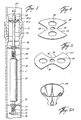
- a tubular member 10 having the internal upset portion 12 for securing sections of the tubular member together is illustrated, which is here shown as internal upset tubing or drill pipe used in the drilling or working over of wells in a well bore or casing, not shown. While internal upset drill pipe or tubing is illustrated, the wiper of the present invention can be used for cleaning liquids from the internal walls of any member, such as drill pipe, tubing, casing and various tools and apparatus having bores or passages through them. As illustrated in Figure 1, the wiper 14 is illustrated floating in the liquid L, such as drilling mud, well liquid and the like.
- drilling mud which is circulated in the bore hole during drilling operations.
- these muds are expensive and include chemicals, wetting materials and the like and it is highly desirable to wipe the interior walls of the tubular member clean as it is withdrawn from the bore hole or casing when coming out of the hole in drilling or workover operations.
- the term "bore hole” as used herein means both cased and uncased bore holes, that is, the tubular member may be in casing in a bore hole or may be simply in an uncased bore hole.
- the wiper includes elongate, tubular mandrels 16 and 16a to which an elongate float comprising a tubular buoyant chamber 18 is secured to the lower and a mandrel 16b is secured to the lower end of the buoyant chamber 18.
- the buoyant chamber 18 is effective to float the wiper 14 in liquids L in the bore of the tubular member 10 in which the wiper is to be used and the buoyant chamber 18 is closed at its top and bottom by the closure members 20 and 22, respectively.
- the mandrel 16 extends upwardly above the top 20 of the buoyant chamber 18 a substantial distance and the lower mandrel 16b extends below the bottom 22 of the buoyant chamber 18 a relatively short distance, as illustrated.
- a flexible centralizer 28, here shown as having the radially outwardly extending flexible arms 30 (see Figure 3) is removably secured to the mandrel 16a below the buoyant chamber 18.
- the arms 30 extend outwardly radially a distance sufficient to centralize the lower end of the wiper 14 in the bore of the tubular member 10.
- the lower end of the mandrel 16a is threaded into the upper closure end 20 of the buoyant chamber 18.
- the nut or enlargement 32, a packing member 34 and a friction ring 36 are provided so that when the nut 32 is completely threaded into the threaded opening in the upper closure member 20, the packing is compressed against the upper surface thereof and the lower surface of the nut 32 thereby effectively closing the upper closure member 20, and hence, the upper portion of the float chamber 18.
- a first tubular spacing member 36 is slidably disposed about the mandrel 16 and spaces the first wiper assembly, here shown as the wiper members 48 and 50 slightly above the spring 38.
- a pair of support rings or washers 52 and 54 are provided at the top and bottom of the wiper members 48 and 50, all of which is slipped over the mandrel 16 and moved along the mandrel 16 until such time as the spacer 46 engages the lock ring 44.
- a second tubular spacing member 56 is provided which also is slidable about the mandrel 16 and a second wiper assembly, here shown as the wiper members 48a and 50a and the stop rings or washers 52a and 54a, is slidable on the mandrel 16.
- the wiper members 48a and 50a as well as the support rings or washers 52a and 54a advantageously can be and are the same as those of the first wiper assembly.
- the spacer 56 is of sufficient length to space the first and second wiper assemblies axially a distance from one another to permit ready passage through the smallest bore of the tubular member 10, for example, the internal upset portion 12, illustrated in Figure 1.
- a retainer head 58 is provided which is internally threaded at its lower end, as indicated by the reference numeral 60, into which the upper threaded end 62 of the mandrel 16 is threaded which thus securely maintains the spaced first and second wipers or wiper assemblies in the desired position.
- the retainer 58 has a fishing head at its upper end, here shown as the downwardly facing annular shoulder 62 and the upwardly tapered upper surface 64 so that it can readily be grappled by a fishing tool or grapple on a wire line, not shown, for removal from the bore hole from the tubular member 10, when desired. Since fishing tools and wire lines are well known and are commonly used in drilling, no detailed discussion or description thereof is deemed necessary or given.
- the centralizer 28 is connected below the buoyant chamber 18 and to its lower closure member 22 by means of the lower mandrel 16b which is threaded at its upper end 66 and is threaded into the threaded opening 68 in the lower closure member 22.
- An internally threaded locking ring or nut 70 is provided so that the lower mandrel 16b can be readily and releasably secured to the lower end of the buoyant chamber 18.
- the lower end 72 of the lower mandrel 16b is also threaded so that it can be threaded into the internal threads, not shown, of the nut 74.
- the centralizer 28 is provided with the opening 76, the retainer rings or washers 78 are disposed on both sides of the centralizer 28 and a threaded nut 80 is provided so that the centralizer is securely but releasably secured to the lower mandrel 16a.
- a coil spring 82 is secured to the threaded nut 74 at its upper end and to a lower threaded nut 84 at its lower end to which a guide member 86 is secured by means of the threaded nut 88.
- the components of the wiper assembly which could contact the inner walls of the tubular members, normally made of steel, are made of an intert material, such as aluminium alloy and rubber, to avoid creating an explosive condition when operating at high rates of speed. Frequently, methane gas is present in the mud system and when combined with oxygen an explosive condition is present. Thus, the wiper is "explosion proof.”
- the wiper members 48, 50, 48a and 50a are best illustrated in Figures 4, 5 and 5a to which reference is now made. Each of these members, of course, has an opening 90 and 92, respectively, of a size so that they will slide over the mandrel 16.
- the wiper members 48, 50, 48a and 50a are generally disc-like members which have substantially cut out portions 94 and 96 on opposite sides to permit a substantial flexing, for example, as illustrated in Figure 5a, when passing through very restricted openings in tubular member 10.
- Each of the wiper members 48, 50, 48a and 50a have the openings 98 and 100 to permit passage or drainage of liquid in the tubular member 10 through the wiper assemblies.
- the wiper members 48 and 50 and 48a and 50a are disposed together in the positions as illustrated in Figures 4 and 5, that is 90° from one another to ensure complete circumferential wiping of the interior walls of the tubular member 10, and yet, the wiper members 48 and 50 are such so that they will readily contract and pass through the smallest openings in various tubular members which it is desired to be wiped clean so that the wiper 14 will remain in the liquid held in the tubular member 10 rather than becoming stuck therein and being pulled up out of the hole inside the tubular member.
- the flexible wipers are formed of a flexible material and may be made of any suitable inert material, such as rubber, and when assembled have a circumferential outer surface which extends outwardly far enough to engage and wipe the walls of the largest bore of the tubular member 10 in which it is used, yet they are flexible enough to readily retract to pass through and wipe the smallest bore thereof.
- the wipers may be single discs or take other forms and any number of drain openings can be provided.
- the form of wipers illustrated, however, have been effective in use. In this connection, it is essential that the wipers be spaced axially a distance from one another to permit ready passage through the smallest bore, for example, the internal upset portion 12, of the tubular member 10.
- the flexible wipers are spaced a distance slightly greater than the distance of the internal upset portion so that only one of them is in the internal upset portion at a time. They may be spaced a slightly less distance, it only being necessary that the flexible members not be so close together that in their retracted position they will cause the wiper to remain in the restricted portion as the tubular member is withdrawn from the well.
- any number can be used, it only being necessary that the wipers flex sufficiently and are spaced apart enough axially so that they readily pass through restricted openings by gravity, that is, by the weight of the floating wiper. These distances are readily determined in manufacturing the wiper 10 for various end uses.
- the arms 30 of the centralizer 28 should be made of an inert flexible material, such as rubber, so that the arms can retract readily and easily and not become stuck in the bore of the tubular member 10, yet avoid an explosive condition.
- Means are provided for equalizing the pressure within the buoyant chamber 18 with the pressure in the well bore when encountering pressure to prevent damage to the buoyant chamber 18 or to collapse it, thus permitting the wiper to sink in the liquid L and not function as intended.
- a passage 102 is provided through the lower mandrel 16b which provides a passage into the interior of the buoyant chamber or float 18.
- the passage 102 is normally closed by the resilient plug 104, which may be omitted as subsequently set forth, which is forced upwardly into the buoyant chamber 18 under any desired difference of pressure between the exterior and the interior of the buoyant chamber 18 so that when pressure is unexpectedly encountered in use, the plug 104 will flow into the buoyant chamber 18 thus permitting flow of pressure in the passage 102 in the mandrel 16b into the interior of the buoyant chamber 18, thereby equalizing the pressure within the buoyant chamber 18 with the pressure in the tubular member or in the well bore.
- Any desired pressure equalizing means can be used to equalize the pressure within the buoyant chamber with that outside of it to prevent collapsing of the buoyant chamber or float 18, as desired.
- the wiper floats in the liquid L, being buoyed into a floating position by the buoyant chamber 18 with the wipers 48 and 50 and 48a and 50a above the liquid L.
- the wiper 14 floats in the liquid L, gravity retaining it therein, and the flexible wiper members 48, 50, 48a and 50a wipe the inner walls or bore of the tubular member 10 of liquid, such as drilling mud, oil and the like, so that when the tubular members are withdrawn to the derrick floor and disconnected these liquids do not spill on the floor.
- the plug 104 is forced by the pressure into the buoyant chamber 18 thus equalizing pressure within the buoyant chamber 18 with the outside pressure and thus preventing damage to or malfunctioning of the wiper 14.
- the springs 38 and 82 permit canting or angular movement of parts of the wiper 14 with respect to one another to prevent the wiper 14 from becoming stuck in a portion of the tubular member 10.
- a grapple on a wire line can be lowered inside the passage or bore of the tubular member 10, the fishing head 62 grappled, and the wiper 14 readily removed, or the wiper 14 can be pumped out by reversing pumping of the mud.
- a small applied weight such as 2 or more pounds will force the wiper 14 to the bottom of the drill string 10 so as not to interfere with remedial action. On release of the applied weight, the wiper will rise and float as before.
- the fishing/retainer head 58 is removed, the worn or damaged wiper members, washers, and spacer, slid off and replacements reassembled on the upper portion 24 of the mandrel 16 and the fishing/retainer head 58 replaced, as previously described.
- the centralizer 28 can be removed and replaced simply by unthreading the nut 88, removing the centralizer 28 and replacing it, and rethreading the nut 88 into place, as described previously.
- the distance between the flexible wipers is a function of the pipe size and the tool joint or apparatus in which it is to be used. For example, for many uses, a 20 inch spacing between the wipers is satisfactory.
- the dimensions of the buoyant chambers 18 are a function of the dimensions or internal diameter of the pipe, tool joint or apparatus in which the wiper 14 is to be used and to compensate for the weight involved and to float the wiper 14. These are all determined in advance readily and easily for a particular end use, that is, pipe or tool joint or apparatus size.
- an elongate or mandrel- like bolt 88c is provided, which has the passage 102c, and which threads into the threaded opening 68 at the lower end 22 of the buoyant chamber 18.
- a spacing and weight like member 70c is provided immediately below the bottom 22 of the buoyant chamber 18, and below it is provided the washer 78c, the flexible centralizer 28c with its flexible arms 30c, a lock ring 78c, the washer 74c, the coil spring 82c, the tubular spacer member 106 which bears against the lower portion of the coil spring 82c and surrounds the elongate bolt 88c, the washer 84c, and the guide member 86c.
- the lower portion can be assembled and secured together readily and easily simply by threading the bolt 88c into the threaded opening 68 in the bottom 22 of the buoyant chamber 18; and can be disassembled by unthreading the bolt 88c.
- the buoyant chamber 18 is at all time in pressure equalization with its surroundings by virtue of the passage 102c. Also, air is entrapped within the buoyant chamber 18 which provides sufficient buoyancy for the wiper to float in the drilling mud, all as previously described.
- the wipers can take a variety of forms and shapes, and the mandrels and spacers need not be tubular. Also, the wiper can be used to wipe other than tubular bores.
- the present invention therefore is well suited and adapted to attain the objects and ends and has the advantages and features mentioned as well as other inherent therein.
Landscapes
- Life Sciences & Earth Sciences (AREA)
- Engineering & Computer Science (AREA)
- Geology (AREA)
- Mining & Mineral Resources (AREA)
- Physics & Mathematics (AREA)
- Environmental & Geological Engineering (AREA)
- Fluid Mechanics (AREA)
- General Life Sciences & Earth Sciences (AREA)
- Geochemistry & Mineralogy (AREA)
- Earth Drilling (AREA)
Claims (9)
Applications Claiming Priority (4)
| Application Number | Priority Date | Filing Date | Title |
|---|---|---|---|
| US2530279A | 1979-03-30 | 1979-03-30 | |
| US25302 | 1979-03-30 | ||
| US06/074,843 US4287948A (en) | 1979-03-30 | 1979-09-13 | Tubular member interior wiper |
| US74843 | 1979-09-13 |
Publications (2)
| Publication Number | Publication Date |
|---|---|
| EP0019993A1 EP0019993A1 (fr) | 1980-12-10 |
| EP0019993B1 true EP0019993B1 (fr) | 1984-03-07 |
Family
ID=26699561
Family Applications (1)
| Application Number | Title | Priority Date | Filing Date |
|---|---|---|---|
| EP80301010A Expired EP0019993B1 (fr) | 1979-03-30 | 1980-03-31 | Dispositif d'essuyage intérieur pour élément tubulaire |
Country Status (3)
| Country | Link |
|---|---|
| US (1) | US4287948A (fr) |
| EP (1) | EP0019993B1 (fr) |
| DE (1) | DE3066795D1 (fr) |
Families Citing this family (20)
| Publication number | Priority date | Publication date | Assignee | Title |
|---|---|---|---|---|
| US4580635A (en) * | 1983-10-21 | 1986-04-08 | Norton Christensen, Inc. | Automatic drill pipe inside wiper |
| US4923011A (en) * | 1989-08-21 | 1990-05-08 | Uvon Skipper | Drill stem mud wiping apparatus |
| US5012866A (en) * | 1989-08-21 | 1991-05-07 | Uvon Skipper | Drill stem mud wiping apparatus |
| US5465791A (en) * | 1994-08-16 | 1995-11-14 | Loitherstein; Joel S. | Resilient spider for well installation |
| US5579843A (en) * | 1994-08-16 | 1996-12-03 | Loitherstein; Joel S. | Resilient spider for well installation |
| USD375888S (en) | 1995-05-22 | 1996-11-26 | Loitherstein Joel S | Resilient spider for well installation |
| US5732774A (en) * | 1995-12-15 | 1998-03-31 | Haggard; Archie K. | Drill wiper assembly |
| US20050121189A1 (en) * | 2003-12-09 | 2005-06-09 | Carroll Charles A. | Reinforced resilient wiper element |
| GB2434600C (en) * | 2004-07-15 | 2010-01-06 | 2K Tech As | Apparatus for wiping the interior of pipes |
| US8739873B2 (en) * | 2010-03-05 | 2014-06-03 | Halliburton Energy Services, Inc. | System and method for fluid diversion and fluid isolation |
| IT1400937B1 (it) | 2010-03-16 | 2013-07-02 | Ricchiuto | Procedimento per ottenere propoli anallergica |
| GB201020031D0 (en) * | 2010-11-25 | 2011-01-12 | Head Phillip | Control of fluid flow in oil wells |
| WO2015160261A1 (fr) | 2014-04-14 | 2015-10-22 | 2K Tools As | Appareil d'essuyage de tiges |
| CN105317402B (zh) * | 2014-06-12 | 2018-08-17 | 中国石油化工股份有限公司 | 用于自喷井的清蜡设备 |
| NO20150195A1 (no) * | 2015-02-10 | 2016-08-11 | 2K Tools As | Avskraperanordning for rør |
| GB2564781B (en) | 2016-05-12 | 2021-09-22 | Halliburton Energy Services Inc | Apparatus and method for creating a plug in a wellbore |
| US20180238135A1 (en) | 2017-02-17 | 2018-08-23 | David Hart | Wellbore casing repair safety tool for low-pressure hydrocarbon wells |
| WO2020176141A1 (fr) | 2019-02-26 | 2020-09-03 | Bomersbach Dan Todd | Appareil pour vérifier le diamètre interne de matériel tubulaire formant une colonne tubulaire |
| CN114687704B (zh) * | 2021-11-12 | 2023-08-01 | 杭州乾景科技有限公司 | 带滑块的无缆清蜡机器人 |
| CN115263239B (zh) * | 2022-09-29 | 2022-12-02 | 胜利油田东方实业投资集团有限责任公司 | 一种油田施工作业用刮管器 |
Family Cites Families (8)
| Publication number | Priority date | Publication date | Assignee | Title |
|---|---|---|---|---|
| US1732277A (en) * | 1928-01-09 | 1929-10-22 | Owens John Henry | Pipe cleaner |
| US2281918A (en) * | 1939-03-25 | 1942-05-05 | Pipe Cleaning Company Inc | Pipe cleaning tool |
| US2257080A (en) * | 1939-10-10 | 1941-09-23 | Texas Co | Drill pipe cleaner |
| US2460481A (en) * | 1947-05-27 | 1949-02-01 | Charles P Mckinney | Drill pipe cleaner |
| US2728398A (en) * | 1954-03-29 | 1955-12-27 | Julian S Taylor | Paraffin scraper |
| US2740480A (en) * | 1954-04-28 | 1956-04-03 | Howard J Cox | Pipe wiper |
| US3265133A (en) * | 1965-07-27 | 1966-08-09 | Burch Julius Gordon | Gas well treatment apparatus |
| US4034807A (en) * | 1975-08-12 | 1977-07-12 | Edgar N. Prince | Inside pipe wiper |
-
1979
- 1979-09-13 US US06/074,843 patent/US4287948A/en not_active Expired - Lifetime
-
1980
- 1980-03-31 DE DE8080301010T patent/DE3066795D1/de not_active Expired
- 1980-03-31 EP EP80301010A patent/EP0019993B1/fr not_active Expired
Also Published As
| Publication number | Publication date |
|---|---|
| US4287948A (en) | 1981-09-08 |
| DE3066795D1 (de) | 1984-04-12 |
| EP0019993A1 (fr) | 1980-12-10 |
Similar Documents
| Publication | Publication Date | Title |
|---|---|---|
| EP0019993A1 (fr) | Dispositif d'essuyage intérieur pour élément tubulaire | |
| US6095583A (en) | Wellbore fishing tools | |
| US4955949A (en) | Mud saver valve with increased flow check valve | |
| US3052302A (en) | Tool carrier with by-pass | |
| US20010040035A1 (en) | Downhole apparatus | |
| US11396797B2 (en) | Sealing plunger lift system and tubing connector | |
| CA2428008A1 (fr) | Methode et dispositif de maintien d'une colonne de fluide dans un anneau de puits de forage | |
| IE51280B1 (en) | Valve means | |
| US8899316B2 (en) | Downhole isolation tool having a ported sliding sleeve | |
| CA2841639C (fr) | Element d'etancheite de fond de trou et appareils connexes | |
| CA2981919A1 (fr) | Extrait de piston-plongeur multicomposante dans un appareil de levage de piston-plongeur de puits | |
| US4221264A (en) | Tubular interior wiper | |
| US3566981A (en) | Hydraulic drilling jar | |
| US3651867A (en) | Combination well clean-out tool and jar | |
| US2956626A (en) | Apparatus for freeing stuck pipe | |
| US2885007A (en) | Anchoring device | |
| USRE32085E (en) | Tubular member interior wiper | |
| US11028661B2 (en) | Fishing neck for plunger | |
| US3392795A (en) | Hydraulic jar | |
| GB2237046A (en) | Drill stem mud wiping apparatus | |
| US5896925A (en) | Tool protection guide | |
| US2667929A (en) | Wiper for strings engaged in wells | |
| US2996131A (en) | Lubricant packed bumper sub | |
| US2294521A (en) | Removable plug for drilling strings | |
| US3279543A (en) | Well tool for removing sand |
Legal Events
| Date | Code | Title | Description |
|---|---|---|---|
| PUAI | Public reference made under article 153(3) epc to a published international application that has entered the european phase |
Free format text: ORIGINAL CODE: 0009012 |
|
| AK | Designated contracting states |
Designated state(s): BE DE FR GB IT NL SE |
|
| 17P | Request for examination filed |
Effective date: 19810428 |
|
| ITF | It: translation for a ep patent filed | ||
| GRAA | (expected) grant |
Free format text: ORIGINAL CODE: 0009210 |
|
| AK | Designated contracting states |
Designated state(s): BE DE FR GB IT NL SE |
|
| PGFP | Annual fee paid to national office [announced via postgrant information from national office to epo] |
Ref country code: FR Payment date: 19840328 Year of fee payment: 5 |
|
| PGFP | Annual fee paid to national office [announced via postgrant information from national office to epo] |
Ref country code: SE Payment date: 19840331 Year of fee payment: 5 Ref country code: BE Payment date: 19840331 Year of fee payment: 5 |
|
| PGFP | Annual fee paid to national office [announced via postgrant information from national office to epo] |
Ref country code: NL Payment date: 19840402 Year of fee payment: 5 |
|
| REF | Corresponds to: |
Ref document number: 3066795 Country of ref document: DE Date of ref document: 19840412 |
|
| ET | Fr: translation filed | ||
| PGFP | Annual fee paid to national office [announced via postgrant information from national office to epo] |
Ref country code: DE Payment date: 19840530 Year of fee payment: 5 |
|
| PLBE | No opposition filed within time limit |
Free format text: ORIGINAL CODE: 0009261 |
|
| STAA | Information on the status of an ep patent application or granted ep patent |
Free format text: STATUS: NO OPPOSITION FILED WITHIN TIME LIMIT |
|
| 26N | No opposition filed | ||
| PG25 | Lapsed in a contracting state [announced via postgrant information from national office to epo] |
Ref country code: BE Effective date: 19850331 |
|
| PG25 | Lapsed in a contracting state [announced via postgrant information from national office to epo] |
Ref country code: SE Effective date: 19850401 |
|
| BERE | Be: lapsed |
Owner name: HAGGARD WARD M. Effective date: 19850331 Owner name: HAGGARD ARCHIE K. Effective date: 19850331 |
|
| PG25 | Lapsed in a contracting state [announced via postgrant information from national office to epo] |
Ref country code: NL Effective date: 19851001 |
|
| PG25 | Lapsed in a contracting state [announced via postgrant information from national office to epo] |
Ref country code: FR Free format text: LAPSE BECAUSE OF NON-PAYMENT OF DUE FEES Effective date: 19851129 |
|
| PG25 | Lapsed in a contracting state [announced via postgrant information from national office to epo] |
Ref country code: DE Effective date: 19851203 |
|
| NLV4 | Nl: lapsed or anulled due to non-payment of the annual fee | ||
| REG | Reference to a national code |
Ref country code: FR Ref legal event code: ST |
|
| ITCP | It: supplementary protection certificate |
Spc suppl protection certif: CCP 60 |
|
| EUG | Se: european patent has lapsed |
Ref document number: 80301010.7 Effective date: 19860128 |
|
| PGFP | Annual fee paid to national office [announced via postgrant information from national office to epo] |
Ref country code: GB Payment date: 19990323 Year of fee payment: 20 |
|
| PG25 | Lapsed in a contracting state [announced via postgrant information from national office to epo] |
Ref country code: GB Free format text: LAPSE BECAUSE OF EXPIRATION OF PROTECTION Effective date: 20000330 |
|
| REG | Reference to a national code |
Ref country code: GB Ref legal event code: PE20 Effective date: 20000330 |