EP0020074B1 - Procédé de soudage de sections de tube métallique à l'aide d'explosifs - Google Patents
Procédé de soudage de sections de tube métallique à l'aide d'explosifs Download PDFInfo
- Publication number
- EP0020074B1 EP0020074B1 EP80301642A EP80301642A EP0020074B1 EP 0020074 B1 EP0020074 B1 EP 0020074B1 EP 80301642 A EP80301642 A EP 80301642A EP 80301642 A EP80301642 A EP 80301642A EP 0020074 B1 EP0020074 B1 EP 0020074B1
- Authority
- EP
- European Patent Office
- Prior art keywords
- explosive
- welding
- charges
- pipe
- band
- Prior art date
- Legal status (The legal status is an assumption and is not a legal conclusion. Google has not performed a legal analysis and makes no representation as to the accuracy of the status listed.)
- Expired
Links
- 239000002360 explosive Substances 0.000 title claims abstract description 109
- 238000003466 welding Methods 0.000 title claims abstract description 73
- 238000000034 method Methods 0.000 title claims abstract description 30
- 239000002184 metal Substances 0.000 title claims abstract description 21
- 229910052751 metal Inorganic materials 0.000 title claims abstract description 21
- 230000000977 initiatory effect Effects 0.000 claims abstract description 43
- 230000001154 acute effect Effects 0.000 claims description 5
- 238000005474 detonation Methods 0.000 abstract description 35
- 230000035939 shock Effects 0.000 abstract description 14
- 238000010276 construction Methods 0.000 abstract description 7
- 230000005540 biological transmission Effects 0.000 description 8
- 230000000254 damaging effect Effects 0.000 description 7
- 239000000463 material Substances 0.000 description 7
- 238000005422 blasting Methods 0.000 description 4
- 230000000694 effects Effects 0.000 description 4
- PAWQVTBBRAZDMG-UHFFFAOYSA-N 2-(3-bromo-2-fluorophenyl)acetic acid Chemical compound OC(=O)CC1=CC=CC(Br)=C1F PAWQVTBBRAZDMG-UHFFFAOYSA-N 0.000 description 3
- 229910000831 Steel Inorganic materials 0.000 description 3
- 238000004021 metal welding Methods 0.000 description 3
- 239000003921 oil Substances 0.000 description 3
- 238000002360 preparation method Methods 0.000 description 3
- 239000010959 steel Substances 0.000 description 3
- TZRXHJWUDPFEEY-UHFFFAOYSA-N Pentaerythritol Tetranitrate Chemical compound [O-][N+](=O)OCC(CO[N+]([O-])=O)(CO[N+]([O-])=O)CO[N+]([O-])=O TZRXHJWUDPFEEY-UHFFFAOYSA-N 0.000 description 2
- FFMMWFUIRQUAKA-UHFFFAOYSA-O azanium;2-methyl-1,3,5-trinitrobenzene;nitrate Chemical compound [NH4+].[O-][N+]([O-])=O.CC1=C([N+]([O-])=O)C=C([N+]([O-])=O)C=C1[N+]([O-])=O FFMMWFUIRQUAKA-UHFFFAOYSA-O 0.000 description 2
- 239000003999 initiator Substances 0.000 description 2
- 239000000203 mixture Substances 0.000 description 2
- 239000004576 sand Substances 0.000 description 2
- 238000007493 shaping process Methods 0.000 description 2
- 239000007787 solid Substances 0.000 description 2
- 238000012360 testing method Methods 0.000 description 2
- 108010010803 Gelatin Proteins 0.000 description 1
- SNIOPGDIGTZGOP-UHFFFAOYSA-N Nitroglycerin Chemical compound [O-][N+](=O)OCC(O[N+]([O-])=O)CO[N+]([O-])=O SNIOPGDIGTZGOP-UHFFFAOYSA-N 0.000 description 1
- 239000004568 cement Substances 0.000 description 1
- 238000007796 conventional method Methods 0.000 description 1
- 238000010891 electric arc Methods 0.000 description 1
- 238000005516 engineering process Methods 0.000 description 1
- 238000004880 explosion Methods 0.000 description 1
- 239000000295 fuel oil Substances 0.000 description 1
- 229920000159 gelatin Polymers 0.000 description 1
- 235000019322 gelatine Nutrition 0.000 description 1
- 235000011852 gelatine desserts Nutrition 0.000 description 1
- 229960003711 glyceryl trinitrate Drugs 0.000 description 1
- 238000005304 joining Methods 0.000 description 1
- 238000002844 melting Methods 0.000 description 1
- 230000008018 melting Effects 0.000 description 1
- 150000002739 metals Chemical class 0.000 description 1
- 230000003014 reinforcing effect Effects 0.000 description 1
- 230000000284 resting effect Effects 0.000 description 1
- 238000000926 separation method Methods 0.000 description 1
- 239000002002 slurry Substances 0.000 description 1
- 230000003313 weakening effect Effects 0.000 description 1
- 238000005303 weighing Methods 0.000 description 1
Images
Classifications
-
- B—PERFORMING OPERATIONS; TRANSPORTING
- B23—MACHINE TOOLS; METAL-WORKING NOT OTHERWISE PROVIDED FOR
- B23K—SOLDERING OR UNSOLDERING; WELDING; CLADDING OR PLATING BY SOLDERING OR WELDING; CUTTING BY APPLYING HEAT LOCALLY, e.g. FLAME CUTTING; WORKING BY LASER BEAM
- B23K20/00—Non-electric welding by applying impact or other pressure, with or without the application of heat, e.g. cladding or plating
- B23K20/06—Non-electric welding by applying impact or other pressure, with or without the application of heat, e.g. cladding or plating by means of high energy impulses, e.g. magnetic energy
- B23K20/08—Explosive welding
-
- B—PERFORMING OPERATIONS; TRANSPORTING
- B23—MACHINE TOOLS; METAL-WORKING NOT OTHERWISE PROVIDED FOR
- B23K—SOLDERING OR UNSOLDERING; WELDING; CLADDING OR PLATING BY SOLDERING OR WELDING; CUTTING BY APPLYING HEAT LOCALLY, e.g. FLAME CUTTING; WORKING BY LASER BEAM
- B23K20/00—Non-electric welding by applying impact or other pressure, with or without the application of heat, e.g. cladding or plating
- B23K20/06—Non-electric welding by applying impact or other pressure, with or without the application of heat, e.g. cladding or plating by means of high energy impulses, e.g. magnetic energy
- B23K20/08—Explosive welding
- B23K20/085—Explosive welding for tubes, e.g. plugging
Definitions
- This invention relates to the art of metal welding with explosives. More particularly, the invention is concemed with the joining together by explosive welding of sections of large diameter steel pipe as are used, for example, in the construction of major oil and gas pipelines.
- a continuous layer of explosive is placed around the flange and a solid supporting die is positioned within the tubes adjacent to the explosive. Upon detonation of the explosive, the flange is driven against the mated tube and is welded thereto and the die is then withdrawn.
- an inwardly tapered section of the inner tube of a mated pair can be provided. In this case an inner band of explosives and an outer support die is employed. While in the example provided by Maher et al., only a comparatively small tube diameter of 9 1/2" was welded, Maher et al.
- a single external explosive charge is detonated over a metal sleeve which embraces the butted pipe ends and an internal mandrel is employed adjacent the sleeve.
- the welding explosive charge is initiated by means of a second explosive ring primer charge which has a higher detonation velocity than the principal welding explosive charge which primer charge is indented into and is positioned around the welding charge at a mid-point thereof. Initiation of the welding charge by the high velocity primer charge is said to avoid or minimize stress caused by circumferentially colliding shock waves.
- the method of welding of the present invention takes into account the following features which are deemed essential to the explosive welding of large diameter pipeline sections under severe conditions of weather or terrain:
- a method of welding together a pair of metal tube sections by positioning the ends of the tube sections, which are for linear connection, telescopically together in male/female relationship, the female pipe end being flared outward at an acute angle to the wall of the pipe, and positioning a band-like charge (6 or 7) of welding explosive against the surface of one of the tube sections remote from the other section and adjacent to the tube end, characterised by providing opposite internal and external substantially concentric, continuous band-like charges of welding explosive against the exterior surface of said female flared tube end and the interior surface of said male tube end, said explosive band charges having a tapered or wedged shape in the width cross-section of the band, and said wedged or tapered band charges being adapted for placement so that the thicker edge of the band is closest to the narrow diameter of the said female flared pipe area and initiation of the band charges is made along the said thicker edge and simultaneously detoning said charges in order to drive together the welding explosive band charges, said initiating means comprising an elongated cord-
- the welding charges are detonated simultaneously, preferably by means of very high detonation velocity initiation explosive charges placed along a leading edge of each welding explosive charge.
- the initiating explosive charges are preferably each set off by a single detonator means.
- the explosive charges are covered with tamping material.
- advantage is taken of the known technology to provide an improved pipe welding method wherein the explosive welding charge is initiated by means of a very high VOD initiating charge which produces shock fronts in the welding explosive charges moving around the pipe at a very large angle to the pipe axis. At the termination point, the shock fronts meet at a very large angle and hence the damaging effect of any colliding circumferential wave fronts is reduced.
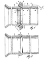
- 1 represents the surface cleaned end of a male steel pipe section 2 of, say, 48 inch (122 cm) diameter.
- the wall thickness of pipe 2 is approximately 0.75 inch (1.9 cm).
- Numeral 3 represents the expanded or flared and cleaned end of a female pipe section 4 of similar wall thickness as pipe 2.
- Flared end 3 describes the acute angle of from about 5° to about 8°, preferably 6°, when male pipe end 1 is fitted into and against the inner cleaned surface 5 of flared end 3.
- a band charge of explosive having a tapered, wedge-shaped or stepped cross-section is positioned in contact with the outside face of flared end 3.
- a second equivalent band charge of explosive 7 of similar cross-sectional shape to charge 6 is positioned in contact with the inside face of pipe end 1 at a position which underlayes explosive charge 6.
- the leading edges of charges 6 and 7 are aligned with the ends of pipes 2 and 4.
- Packaged tamping material 14 and 15 in the form of, for example, packaged sand, may be overlayed against and on top of the charges 6 and 7.
- Charge 7 may be held in position against the inner face of pipe end 1 by means of, for example, support spokes 8.
- At thick edge of explosive charge 6 and in initiating circumferential contact therewith is a cord-like explosive charge 9.
- a similar cord-like explosive charge 10 is in initiating circumferential contact with a corresponding edge of explosive charge 7.
- cord-like charges 9 and 10 are at least 50% greater than the velocity of detonation of the explosive charges 6 and 7.
- initiating transmission means 11 and 12 which may be, for example, lengths of standard detonating cord or lengths of "Nonel" (Reg. trademark) energy transmission cord.
- cord-like charges 9 and 10 may be initiated by means of separate adjacent fast- acting electric detonators such as the exploding bridge wire type.
- Initiating means 11 and 12 are joined to a common detonator 13 which may be, for example, an electric blasting cap.
- Band charges 6 and 7 may be provided by the explosives manufacturer in preassembled units with cord-like charges 9 and 10 and initiating means 11 and 12 attached thereto.
- Charge 7 may be made in the form of a wheel and is tailored to fit exactly within male pipe end 1.
- Charge 6 may be made in the form of a flexible belt having a length equal to the outside circumference of flared end 3 and ready for securing thereto by means of tape, contact cement, or the like.
- a prepared welding explosives charge 7 having cord-like initiating charge 10 and initiation transmission means 12 attached thereto, is fitted within the circumference and close to the cleaned end 1 of a pipe 2.
- a second similar sized pipe 4 having an outwardly flared cleaned end 3 is abutted against the leading edge of pipe end 1 so that end 1 is overlapped by the flared section 3.
- a prepared explosive charge 6 having cord-like initiating charge 9 and initiation transmission means 11 attached thereto, is fitted around the outside circumference of flared end 3 to directly overlay internal charge 7.
- Pre-packaged tamping materials 14 and 15 are secured over charges 6 and 7.
- energy shock waves are simultaneously transmitted along initiation transmission means 11 and 12 where they reach and simultaneously set off cord-like explosive charges 9 and 10. Because cord-like charges 9 and 10 are of substantially greater detonation velocity than the explosive which comprises charges 6 and 7, the detonation fronts in welding charges 6 and 7 propagate faster around the pipe than along the pipe axis.
- the detonation fronts are thus inclined at a large angle to the pipe axis.
- the detonation fronts in the charges 6 and 7 meet at a large angle to reduce the damaging effect of the head-on collision of detonation fronts.
- the detonation velocity of the explosive used in cord-like charge 10 will necessarily have to be prepared having a calculated value slower than that of cord-like charge 9 to compensate for a shorter circumferential distance inside the pipe and to maintain an equal and opposite balancing force on the pipes during the simultaneous detonation of charges 6 and 7.
- a suitable cord-like initiator which may be so prepared is the hollow detonating fuse described by Prior in United States patent No. 3,730,096.
- the amount and kind of explosive used for the welding charges 6 and 7 will depend upon the type of metal being welded, its strength characteristics, its melting temperature, its thickness and the like. From a knowledge of the properties of both metals and explosives, a charge type can be selected to produce sufficient pressure at the weld site to achieve the desired results.
- Typical of the explosives found useful in metal welding are amatol (mixture of TNT and ammonium nitrate), ANFO (ammonium nitrate/fuel oil mixtures), slurries, nitroglycerine-based dynamites and gelatins, and sheet explosives. These welding explosives generally have detonation velocities ranging from about 3000M to about 5000M per second.
- the cord-like charges employed to initiate the welding charges comprise explosive material, preferably detonating cords, having a very high detonation velocity, essentially at least 50% greater than the detonation velocity of the welding charge explosive.
- a high detonation velocity hollow cord as disclosed by Prior in United States patent No. 3,730,096, which may have a detonation velocity as high as 8000M per second or more may be simply incorporated or fixed along the edge of the welding explosive charge in the explosive factory and may also be easily connected to an initiation transmission means such as low energy detonating cord or "Nonel" (Reg. Trademark) energy transmission cord.
- a further and surprisingly unexpected advantage may be gained by employing a hollow type detonating cord as the initiation means for the welding explosive charge. It has been observed that when a length of this hollow type cord is placed on a soft metal plate and is initiated simultaneously at each end, the point at which the explosive waves meet (the Dautriche effect), as indicated by an impression left on the metal plate, is doubled. That is, two spaced-apart marks or impressions are left on the metal plate instead of the single mark left when conventional solid core detonating cord is used. It is seen therefore that it is an intrinsic quality of the hollow type cord to more widely distribute or dissipate the energy from meeting shock waves and hence the damaging effect on the metal against which the detonation takes place is reduced.
- the following example describes the welding of two shortened sections of standard 48 inch (122 cm) diameter steel pipe sections at a test site using the method of the invention.
- Two part sections of large diameter pipe of the type used in the construction of large volume oil pipelines were selected for welding.
- the pipe was 48 inch (122 cm) in outside diameter and had a wall thickness of 0.72 inch (1.83 cm).
- An 11.5 inch (29.2 cm) length of one end of a first pipe section (female) was cleaned and flared outward at an angle of about 6° to the horizontal pipe wall.
- One end of the second (male) pipe section was cleaned and fitted into the female flared end of the first section to make circumferential contact between the inner face of the flared portion and the outer leading edge of the male end. This resulted in a 5 inch (12.7 cm) overlap of the flared section over the male end.
- -Welding explosive charges made from amatol (80% ammonium nitrate and 20% TNT) having a detonation velocity of about 4000M per second were prepared in curved cardboard containers which were assembled to form two continuous rings weighing about 24 pounds (10,9 kg) each.
- the rings had a rectangular stepped cross-section one inch (2.54 cm) thickx2.5 (6.4 cm) wide stepped to 0.75 inch (1.91 cm) thickx2.5 inch (6.4 cm) wide.
- the total width was 5 inch (12.7 cm) and the total length was made to fit the outside circumference of the female pipe section for one ring, and the inside circumference of the male pipe section for the other.
- the first outside explosive welding charge was secured fully around the exterior circumference of the flange of the female pipe section with the thickest edge of the charge closest to the body of the pipe.
- the second inside explosive welding charge was fixed around the inside circumference of the male end of the second pipe section at a position where the charge was overlayed by the exterior charge, the thick edge being aligned with the end of the pipe.
- an initiating length of high detonation velocity detonating cord having an explosive content of 110 grains of PETN per foot (360 grains of PETN per m) of length.
- the velocity of detonation (VOD) of the initiation cord used with the outside, flange- adjacent charge was 8450 m per second.
- the VOD of the cord used with the inner, male end- adjacent charge was adjusted to 7430 m per second or 13.7% less than the VOD of the outside cord in order to compensate for the 13.7% shorter length of the loop of the inside cord compared to the loop of outside cord.
- the reduced VOD was accomplished butting segments of fast and slow cords so that the average velocity was at the required value.
- To each length of the high VOD detonating' (initiating) cord was connected a length of -standard detonating cord sufficiently long to reach the pipe section end remote from the flanged end.
- the positions of the point of connection of the standard detonating cord lengths to the high VOD initiating cord were also overlayed so that initiation of both inner and outer welding charges would take place at exactly superimposed locations.
- the energy wave front produced by the detonation of the welding charges proceeded in a direction mainly across the width of the charge and hence substantially in a direction parallel to the pipe longitudinal axis and caused the overlapped pipe areas to be driven together to produce a continuous welded connection.
- An examination of a cut-away portion of the welded area showed that the fully welded area of the five inches long (12.7 cm) overlayed flange section was approximately 3 inches (7.6 cm) in length which area extended around the circumference of the pipe.
- An approximate one inch (2.54 cm) long section from the end of each of the male and female overlayed areas was not completely bonded due to end effects and the lower efficiency of the explosive in the run up.
- the pipe was carefully examined at a point 180° from the point of initial initiation of the high VOD hollow cord, for any evidence of structural damage or imperfect weld caused by possible circumferential- colliding wave fronts. No evidence of any such damage could be found.
- the weld was also compared with conventional electric arc welds in similar material for resistance to separation or rupture.
- the explosive weld was judged superior by several testing techniques. Because of the .great strength of the explosive weld, it is assumed that any pipeline assembled by explosive welding method of the present invention would display improved resistance to leakage and to longitudinal rupture, common failures in oil and gas pipelines.
- the welding method of the invention thus, unlike many prior art methods, requires no mechanical resistance such as an internal or an external die or mandrel in order to be practised.
- the method employs counterbalancing internal and external explosive forces in order to drive together the metal parts to produce a welded connection.
- the metal surfaces to be welded are assembled so that an acute angle of about 6° to 8° is described between their faces. Because of the method of initiation used, the wave fronts in the welding explosives are caused to move around the pipe while being maintained at superimposed location and at a large angle to the pipe axis and hence the damaging effects of unbalancing and colliding circumferential shock waves are reduced or prevented.
- the simplicity of the method of initiation and assembly of the charges in the field results in speedy, safe and economic operation.
Landscapes
- Engineering & Computer Science (AREA)
- Mechanical Engineering (AREA)
- Pressure Welding/Diffusion-Bonding (AREA)
- Arc Welding In General (AREA)
- Lining Or Joining Of Plastics Or The Like (AREA)
- Butt Welding And Welding Of Specific Article (AREA)
- Non-Disconnectible Joints And Screw-Threaded Joints (AREA)
- Resistance Welding (AREA)
Claims (2)
Priority Applications (1)
| Application Number | Priority Date | Filing Date | Title |
|---|---|---|---|
| AT80301642T ATE1848T1 (de) | 1979-05-21 | 1980-05-20 | Verfahren zum schweissen von metallrohrteilen mit sprengladungen. |
Applications Claiming Priority (2)
| Application Number | Priority Date | Filing Date | Title |
|---|---|---|---|
| US06/040,514 US4248373A (en) | 1979-05-21 | 1979-05-21 | Explosive charge for explosive welding of large diameter metal pipe |
| US40514 | 1979-05-21 |
Publications (2)
| Publication Number | Publication Date |
|---|---|
| EP0020074A1 EP0020074A1 (fr) | 1980-12-10 |
| EP0020074B1 true EP0020074B1 (fr) | 1982-11-24 |
Family
ID=21911387
Family Applications (1)
| Application Number | Title | Priority Date | Filing Date |
|---|---|---|---|
| EP80301642A Expired EP0020074B1 (fr) | 1979-05-21 | 1980-05-20 | Procédé de soudage de sections de tube métallique à l'aide d'explosifs |
Country Status (11)
| Country | Link |
|---|---|
| US (1) | US4248373A (fr) |
| EP (1) | EP0020074B1 (fr) |
| JP (1) | JPS55156686A (fr) |
| KR (1) | KR840000391B1 (fr) |
| AT (1) | ATE1848T1 (fr) |
| AU (1) | AU5801580A (fr) |
| BR (1) | BR8003121A (fr) |
| CA (1) | CA1117795A (fr) |
| DE (1) | DE3061143D1 (fr) |
| NO (1) | NO151229C (fr) |
| ZA (1) | ZA802962B (fr) |
Families Citing this family (9)
| Publication number | Priority date | Publication date | Assignee | Title |
|---|---|---|---|---|
| SE427162B (sv) * | 1981-10-26 | 1983-03-14 | Nitro Nobel Ab | Forfarande vid skarvning av metallelement genom explosionssvetsning |
| SE458302B (sv) * | 1982-12-03 | 1989-03-13 | Nitro Nobel Ab | Anordning foer att aastadkomma ett skarvfoerband mellan tvaa metalliska roer medelst explosionssvetsning i ett omgivande ooenskat medium saasom vatten |
| FR2811741B1 (fr) * | 2000-07-17 | 2003-06-27 | Imphy Ugine Precision | Procede de fabrication d'un element de structure ayant une paroi metallique de forme generale tubulaire et element de structure |
| US6953141B2 (en) * | 2002-10-25 | 2005-10-11 | Weatherford/Lamb, Inc. | Joining of tubulars through the use of explosives |
| NL2011608C2 (nl) * | 2013-10-14 | 2015-06-16 | Synex Tube B V | Werkwijze voor het door middel van explosielassen aan elkaar bevestigen van ten minste twee metalen werkstukdelen. |
| US20150328712A1 (en) * | 2014-05-19 | 2015-11-19 | Conocophillips Company | Coiled tubing lap welds by magnetic pulse welding |
| CN105436041A (zh) * | 2014-09-19 | 2016-03-30 | 中石化胜利油建工程有限公司 | 钢质管道内涂层玻璃钢补口装置 |
| US10267440B2 (en) * | 2015-08-26 | 2019-04-23 | Hdr, Inc. | Apparatus and method for strengthening welded-lap joints for steel pipeline |
| US11999005B2 (en) | 2021-02-11 | 2024-06-04 | Honda Motor Co., Ltd | Device and methods of multiple spot welding for automotive applications using vaporizing foil actuator welding |
Family Cites Families (9)
| Publication number | Priority date | Publication date | Assignee | Title |
|---|---|---|---|---|
| LU47364A1 (fr) * | 1963-11-18 | 1965-01-17 | ||
| DE1248434B (de) * | 1963-11-18 | 1967-08-24 | Wmf Wuerttemberg Metallwaren | Anordnung zum vorzugsweise oertlichen Plattieren von metallischen Werkstuecken miteinander durch von Explosivstoffen erzeugte Schockwellen |
| US3263323A (en) * | 1965-10-21 | 1966-08-02 | United Aircraft Corp | Fabrication of a continuous peripheral joint |
| NL6701319A (fr) * | 1967-01-27 | 1968-07-29 | ||
| US3650014A (en) * | 1969-08-15 | 1972-03-21 | Alexandr Fedorovich Demchuk | Method of explosive welding of metal plates |
| US3910478A (en) * | 1973-03-12 | 1975-10-07 | Exxon Research Engineering Co | Dual high explosive shape detonation |
| DE2317366B2 (de) * | 1973-04-06 | 1977-09-08 | Bayern-Chemie Gesellschaft für flugchemische Antriebe mbH, 8261 Aschau | Verbindung von rohren beliebigen querschnitts mittels einer detonierenden sprengladung |
| US4046301A (en) * | 1974-07-18 | 1977-09-06 | Exxon Research And Engineering Company | Process for explosively joining two pipe sections |
| BE880037A (fr) * | 1978-11-15 | 1980-05-14 | Glaxo Group Ltd | Cephalosporines a activite antibiotique et procede de preparation |
-
1979
- 1979-05-21 US US06/040,514 patent/US4248373A/en not_active Expired - Lifetime
-
1980
- 1980-04-25 CA CA000350669A patent/CA1117795A/fr not_active Expired
- 1980-05-02 AU AU58015/80A patent/AU5801580A/en not_active Withdrawn
- 1980-05-09 NO NO801393A patent/NO151229C/no unknown
- 1980-05-14 KR KR1019800001892A patent/KR840000391B1/ko not_active Expired
- 1980-05-19 ZA ZA00802962A patent/ZA802962B/xx unknown
- 1980-05-19 BR BR8003121A patent/BR8003121A/pt unknown
- 1980-05-20 AT AT80301642T patent/ATE1848T1/de not_active IP Right Cessation
- 1980-05-20 EP EP80301642A patent/EP0020074B1/fr not_active Expired
- 1980-05-20 DE DE8080301642T patent/DE3061143D1/de not_active Expired
- 1980-05-21 JP JP6659080A patent/JPS55156686A/ja active Pending
Also Published As
| Publication number | Publication date |
|---|---|
| ATE1848T1 (de) | 1982-12-15 |
| JPS55156686A (en) | 1980-12-05 |
| US4248373A (en) | 1981-02-03 |
| EP0020074A1 (fr) | 1980-12-10 |
| NO151229C (no) | 1985-03-06 |
| KR830002569A (ko) | 1983-05-30 |
| NO151229B (no) | 1984-11-26 |
| CA1117795A (fr) | 1982-02-09 |
| NO801393L (no) | 1980-11-24 |
| ZA802962B (en) | 1981-06-24 |
| AU5801580A (en) | 1980-11-27 |
| DE3061143D1 (en) | 1982-12-30 |
| KR840000391B1 (ko) | 1984-03-30 |
| BR8003121A (pt) | 1980-12-23 |
Similar Documents
| Publication | Publication Date | Title |
|---|---|---|
| US4231506A (en) | Method of welding metal pipe sections with explosives | |
| US4981250A (en) | Explosion-welded pipe joint | |
| US3563713A (en) | Explosive welding | |
| US7530485B1 (en) | Method for explosive bonding of tubular metal liners | |
| EP0020074B1 (fr) | Procédé de soudage de sections de tube métallique à l'aide d'explosifs | |
| JPH0371232B2 (fr) | ||
| NO147741B (no) | Fremgangsmaate og innretning for eksplosjonssveising av sylindriske metalliske deler. | |
| US3761004A (en) | Assembly for explosively bonding together metal layers and tubes | |
| US4564226A (en) | System and method for increasing wall thickness on end of pipe on which thread is to be fabricated | |
| US4333597A (en) | Method of explosively forming bi-metal tubeplate joints | |
| US3710434A (en) | Explosive pipe coupling method | |
| US3439408A (en) | Process for initiating explosive and charge therefor | |
| US3806020A (en) | Apparatus for welding of pipe by use of explosives | |
| US3645435A (en) | Means for joining metallic tubes by explosive bonding | |
| US3987952A (en) | Apparatus for explosive welding of hollow cylinders such as pipe | |
| US3985279A (en) | Method for explosive welding tubular members using a mandrel | |
| US3780927A (en) | Envelope for explosive connection of metal pipes | |
| US3744119A (en) | Method for explosively bonding together metal layers and tubes | |
| US4046301A (en) | Process for explosively joining two pipe sections | |
| US4280407A (en) | Explosive package assembly | |
| US4809902A (en) | Method of welding using particle acceleration | |
| Werner | New Swedish Method of Joining Steel Pipe by Explosive Welding | |
| GB1561637A (en) | Composite bodies formed by expansion joining |
Legal Events
| Date | Code | Title | Description |
|---|---|---|---|
| PUAI | Public reference made under article 153(3) epc to a published international application that has entered the european phase |
Free format text: ORIGINAL CODE: 0009012 |
|
| AK | Designated contracting states |
Designated state(s): AT DE FR GB NL SE |
|
| 17P | Request for examination filed |
Effective date: 19801021 |
|
| GRAA | (expected) grant |
Free format text: ORIGINAL CODE: 0009210 |
|
| AK | Designated contracting states |
Designated state(s): AT DE FR GB NL SE |
|
| REF | Corresponds to: |
Ref document number: 1848 Country of ref document: AT Date of ref document: 19821215 Kind code of ref document: T |
|
| REF | Corresponds to: |
Ref document number: 3061143 Country of ref document: DE Date of ref document: 19821230 |
|
| PGFP | Annual fee paid to national office [announced via postgrant information from national office to epo] |
Ref country code: AT Payment date: 19830429 Year of fee payment: 4 |
|
| PGFP | Annual fee paid to national office [announced via postgrant information from national office to epo] |
Ref country code: SE Payment date: 19830430 Year of fee payment: 4 |
|
| PGFP | Annual fee paid to national office [announced via postgrant information from national office to epo] |
Ref country code: FR Payment date: 19830516 Year of fee payment: 4 |
|
| PGFP | Annual fee paid to national office [announced via postgrant information from national office to epo] |
Ref country code: NL Payment date: 19830531 Year of fee payment: 4 |
|
| PGFP | Annual fee paid to national office [announced via postgrant information from national office to epo] |
Ref country code: DE Payment date: 19830624 Year of fee payment: 4 |
|
| PG25 | Lapsed in a contracting state [announced via postgrant information from national office to epo] |
Ref country code: AT Effective date: 19840520 |
|
| PG25 | Lapsed in a contracting state [announced via postgrant information from national office to epo] |
Ref country code: SE Effective date: 19840521 |
|
| PG25 | Lapsed in a contracting state [announced via postgrant information from national office to epo] |
Ref country code: NL Effective date: 19841201 |
|
| GBPC | Gb: european patent ceased through non-payment of renewal fee | ||
| NLV4 | Nl: lapsed or anulled due to non-payment of the annual fee | ||
| PG25 | Lapsed in a contracting state [announced via postgrant information from national office to epo] |
Ref country code: FR Free format text: LAPSE BECAUSE OF NON-PAYMENT OF DUE FEES Effective date: 19850131 |
|
| PG25 | Lapsed in a contracting state [announced via postgrant information from national office to epo] |
Ref country code: DE Effective date: 19850201 |
|
| REG | Reference to a national code |
Ref country code: FR Ref legal event code: ST |
|
| PG25 | Lapsed in a contracting state [announced via postgrant information from national office to epo] |
Ref country code: GB Effective date: 19881118 |
|
| EUG | Se: european patent has lapsed |
Ref document number: 80301642.7 Effective date: 19850417 |
|
| PLBE | No opposition filed within time limit |
Free format text: ORIGINAL CODE: 0009261 |
|
| STAA | Information on the status of an ep patent application or granted ep patent |
Free format text: STATUS: NO OPPOSITION FILED WITHIN TIME LIMIT |