EP0020190A1 - Befestigungsvorrichtung für Wärmetauscher in einem Fahrzeug, insbesondere für Lastkraftfahrzeugwärmetauscher - Google Patents
Befestigungsvorrichtung für Wärmetauscher in einem Fahrzeug, insbesondere für Lastkraftfahrzeugwärmetauscher Download PDFInfo
- Publication number
- EP0020190A1 EP0020190A1 EP80400493A EP80400493A EP0020190A1 EP 0020190 A1 EP0020190 A1 EP 0020190A1 EP 80400493 A EP80400493 A EP 80400493A EP 80400493 A EP80400493 A EP 80400493A EP 0020190 A1 EP0020190 A1 EP 0020190A1
- Authority
- EP
- European Patent Office
- Prior art keywords
- radiator
- cradle
- vehicle
- elastic
- shims
- Prior art date
- Legal status (The legal status is an assumption and is not a legal conclusion. Google has not performed a legal analysis and makes no representation as to the accuracy of the status listed.)
- Granted
Links
- 238000005096 rolling process Methods 0.000 claims abstract description 5
- XLYOFNOQVPJJNP-UHFFFAOYSA-N water Substances O XLYOFNOQVPJJNP-UHFFFAOYSA-N 0.000 claims description 10
- 230000006835 compression Effects 0.000 claims description 5
- 238000007906 compression Methods 0.000 claims description 5
- 239000000463 material Substances 0.000 claims description 2
- 238000001816 cooling Methods 0.000 description 2
- 238000003780 insertion Methods 0.000 description 2
- 230000037431 insertion Effects 0.000 description 2
- 239000000725 suspension Substances 0.000 description 2
- 230000000295 complement effect Effects 0.000 description 1
- 238000010276 construction Methods 0.000 description 1
- 239000002184 metal Substances 0.000 description 1
- 238000012986 modification Methods 0.000 description 1
- 230000004048 modification Effects 0.000 description 1
- 239000007787 solid Substances 0.000 description 1
- 238000003466 welding Methods 0.000 description 1
Images
Classifications
-
- B—PERFORMING OPERATIONS; TRANSPORTING
- B60—VEHICLES IN GENERAL
- B60K—ARRANGEMENT OR MOUNTING OF PROPULSION UNITS OR OF TRANSMISSIONS IN VEHICLES; ARRANGEMENT OR MOUNTING OF PLURAL DIVERSE PRIME-MOVERS IN VEHICLES; AUXILIARY DRIVES FOR VEHICLES; INSTRUMENTATION OR DASHBOARDS FOR VEHICLES; ARRANGEMENTS IN CONNECTION WITH COOLING, AIR INTAKE, GAS EXHAUST OR FUEL SUPPLY OF PROPULSION UNITS IN VEHICLES
- B60K11/00—Arrangement in connection with cooling of propulsion units
- B60K11/02—Arrangement in connection with cooling of propulsion units with liquid cooling
- B60K11/04—Arrangement or mounting of radiators, radiator shutters, or radiator blinds
Definitions
- Fixing device for a radiator in a rolling vehicle, in particular for a truck radiator is
- the present invention relates to the mounting of radiators, in particular cooling radiators, in heavy goods vehicles intended to be operated under severe conditions, for example on vehicles intended to roll on tracks.
- the invention therefore relates to a new device which makes it possible to remedy the drawbacks noted and to very effectively protect the radiator which, moreover, can be produced in a particularly inexpensive manner.
- the fixing device for radiators in a rolling vehicle in particular for a truck radiator, comprises a cradle surrounding the radiator and elastic wedges interposed between the radiator water boxes and the corresponding parts of the cradle , said elastic wedges being maintained under stress to exert a permanent compression force on the radiator.
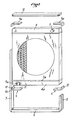
- Fig. 1 is an exploded schematic perspective of a radiator and its support cradle applying the invention.
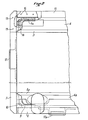
- the freeze 2 is a partial elevation, on a larger scale, partially cut away, illustrating a detail of construction.
- a schematic representation is shown of a cooling radiator for vehicles, in particular for heavy goods vehicles, which comprise tubes 1 and dissipators 2.
- the tubes open into collectors 3, 3a which are covered by water boxes 4, 4a provided with tubes such as those shown in 5 and 5a.
- the radiator itself does not have side cheeks, that is to say that the collectors and water boxes are only connected by the tubes 1. It would not however depart from the scope of the invention if the radiator had side cheeks for connect the small sides of the collectors or water boxes.
- the radiator described above is intended to be mounted in a cradle which has a sole 6, for example constituted by a U-shaped section, and which is joined at its ends to uprights? and 8 also constituted by profiles, for example in a U shape.
- the internal face 11 of the bracket is shaped in a complementary manner to the part of the corresponding wall of the water box 4a.
- the elastic wedges 9 can be solid or, on the contrary, honeycombed, for example having ribs extending in several directions to make a cross-over.
- each wedge in the form of a square is tightened against the wall of the risers 7 and 8.
- other wedges 9a identical to the preceding ones which surround the ends of the water box 4.
- a cover 13 is then placed between the end of the uprights 7, 8.
- the cover 13 is put in place while exerting a pressure on it deforming the long side of the shims 9a and 9 and, then, the cover 13 is fixed to the uprights 7, 8 of the cradle, for example by gussets 14 which are connected to the uprights 7, 8 by welding points 15 and to the cover 13 by bolts or pins 16.
- the radiator is kept under permanent compression stress.
- the elasticity of the shims 9, 9a is chosen taking into account the mass of the radiator proper and a compression force is exerted on the shims such that the natural frequency of the radiator pinched between the different elastic shims is always greater than the frequencies that can be produced by the rolling of the vehicle which includes the radiator.
- the natural frequency of the radiator is greater than 1 Hz, but preferably the compression stress which is exerted is chosen so that this natural frequency is much higher, for example close to 30 Hz.
- the cradle which consists of the sole 6, the uprights 7, 8 and the cover 13, is used to fix the radiator to the vehicle proper by conventional means and, to this end, as illustrated in FIG. 2, it comprises fixing lugs 17, 17a carried by the mon aunts, the sole and possibly the cover.
- the elastic shims consist of rubber or similar material parts, but it would not go beyond the scope of the invention to make them in other ways, for example by metal springs interposed between the lower water box and the sole, on the one hand, and between the upper water box and the cover 13, on the other hand. Similarly, it is possible to combine rubber shims and springs.
Landscapes
- Engineering & Computer Science (AREA)
- Chemical & Material Sciences (AREA)
- Combustion & Propulsion (AREA)
- Transportation (AREA)
- Mechanical Engineering (AREA)
- Cooling, Air Intake And Gas Exhaust, And Fuel Tank Arrangements In Propulsion Units (AREA)
- Vibration Prevention Devices (AREA)
Applications Claiming Priority (2)
| Application Number | Priority Date | Filing Date | Title |
|---|---|---|---|
| FR7911294A FR2455524A1 (fr) | 1979-05-04 | 1979-05-04 | Dispositif de fixation pour radiateur dans un vehicule roulant, notamment pour radiateur de vehicule poids-lourd |
| FR7911294 | 1979-05-04 |
Publications (2)
| Publication Number | Publication Date |
|---|---|
| EP0020190A1 true EP0020190A1 (de) | 1980-12-10 |
| EP0020190B1 EP0020190B1 (de) | 1983-04-06 |
Family
ID=9225050
Family Applications (1)
| Application Number | Title | Priority Date | Filing Date |
|---|---|---|---|
| EP80400493A Expired EP0020190B1 (de) | 1979-05-04 | 1980-04-14 | Befestigungsvorrichtung für Wärmetauscher in einem Fahrzeug, insbesondere für Lastkraftfahrzeugwärmetauscher |
Country Status (8)
| Country | Link |
|---|---|
| US (1) | US4315540A (de) |
| EP (1) | EP0020190B1 (de) |
| BR (1) | BR8002670A (de) |
| DD (1) | DD150446A5 (de) |
| DE (1) | DE3062587D1 (de) |
| ES (1) | ES490972A0 (de) |
| FR (1) | FR2455524A1 (de) |
| PL (1) | PL223987A1 (de) |
Cited By (2)
| Publication number | Priority date | Publication date | Assignee | Title |
|---|---|---|---|---|
| FR2538030A1 (fr) * | 1982-12-16 | 1984-06-22 | Chausson Usines Sa | Echangeur de chaleur a tubes longs pour vehicules poids lourds |
| DE19916475A1 (de) * | 1999-04-13 | 2000-10-19 | Behr Gmbh & Co | Wärmeübertragungseinheit für ein Kraftfahrzeug |
Families Citing this family (13)
| Publication number | Priority date | Publication date | Assignee | Title |
|---|---|---|---|---|
| JPS5784223A (en) * | 1980-11-13 | 1982-05-26 | Nissan Motor Co Ltd | Vibration absorber of vehicle |
| USD295215S (en) | 1985-03-18 | 1988-04-12 | Martin Cory I | Automotive air conditioner evaporator housing |
| US5088572A (en) * | 1991-03-28 | 1992-02-18 | Navistar International Transportation Corp. | Forward control bus chassis with low engine mounting assembly |
| DE9213450U1 (de) * | 1992-10-06 | 1993-01-07 | Cummins Engine Co. Ltd., New Malden, Surrey | Antriebseinheit |
| GB9805379D0 (en) * | 1998-03-14 | 1998-05-06 | Grayson Automotive Services Li | Heat exchanger assemblies for vehicles |
| GB2336662B (en) * | 1998-04-21 | 2002-04-10 | Agco Gmbh & Co | Vehicle cooling radiator arrangement |
| DE19831256A1 (de) * | 1998-07-11 | 2000-01-13 | Behr Gmbh & Co | Halterung für Wärmeübertrager, insbesondere für Kühler von Kraftfahrzeugen |
| JP4400803B2 (ja) * | 1999-09-03 | 2010-01-20 | 本田技研工業株式会社 | 車両用冷却装置 |
| DE10061561A1 (de) * | 2000-12-07 | 2002-06-13 | Behr Gmbh & Co | Modulträger für diverse Wärmeübertrager eines Kraftfahrzeugmotors |
| US7195059B2 (en) * | 2003-05-06 | 2007-03-27 | H2Gen Innovations, Inc. | Heat exchanger and method of performing chemical processes |
| JP2005112268A (ja) * | 2003-10-10 | 2005-04-28 | Nissan Motor Co Ltd | 熱交換器の取付構造 |
| DE102005039090A1 (de) * | 2005-08-06 | 2007-02-08 | Behr Gmbh & Co. Kg | Montageträgersystem |
| JP6804269B2 (ja) * | 2016-11-18 | 2020-12-23 | 三菱重工サーマルシステムズ株式会社 | 熱交換器 |
Citations (5)
| Publication number | Priority date | Publication date | Assignee | Title |
|---|---|---|---|---|
| FR599781A (fr) * | 1925-06-18 | 1926-01-20 | Int Motor Co | Perfectionnements aux supports de radiateur pour automobiles |
| FR1413728A (fr) * | 1964-11-12 | 1965-10-08 | Daimler Benz Ag | Fixation élastique du radiateur sur des voitures automobiles |
| FR1413650A (fr) * | 1964-11-07 | 1965-10-08 | Daimler Benz Ag | Fixation élastique d'un radiateur sur des voitures automobiles |
| FR1600374A (de) * | 1968-12-31 | 1970-07-20 | ||
| US4137982A (en) * | 1977-08-08 | 1979-02-06 | Caterpillar Tractor Co. | Reinforced radiator mounting for heavy vehicles |
Family Cites Families (9)
| Publication number | Priority date | Publication date | Assignee | Title |
|---|---|---|---|---|
| US1447695A (en) * | 1921-09-27 | 1923-03-06 | Claude V Storms | Radiator support |
| US1593244A (en) * | 1921-10-19 | 1926-07-20 | Cutler Auto Radiator Company | Automobile radiator |
| US1840417A (en) * | 1930-03-19 | 1932-01-12 | Mcquay Radiator Corp | Frame and mounting for heat exchange units |
| US1834709A (en) * | 1930-08-22 | 1931-12-01 | Fedders Mfg Co | Radiator mounting |
| US1963429A (en) * | 1932-07-08 | 1934-06-19 | Fred M Young | Radiator |
| US2506051A (en) * | 1947-09-12 | 1950-05-02 | Young Radiator Co | Radiator core mounting |
| US2755874A (en) * | 1951-12-04 | 1956-07-24 | Gen Motors Corp | Motor vehicle radiators resiliently and slidably mounted |
| DE2233737C2 (de) * | 1971-07-12 | 1983-02-03 | Société Anonyme Française du Ferodo, 75017 Paris | Wärmetauscher, insbesondere Kühler für ein Kraftfahrzeug |
| US3858291A (en) * | 1972-01-31 | 1975-01-07 | Garrett Corp | Method of mounting a heat exchanger core |
-
1979
- 1979-05-04 FR FR7911294A patent/FR2455524A1/fr active Granted
-
1980
- 1980-04-14 DE DE8080400493T patent/DE3062587D1/de not_active Expired
- 1980-04-14 EP EP80400493A patent/EP0020190B1/de not_active Expired
- 1980-04-25 US US06/145,269 patent/US4315540A/en not_active Expired - Lifetime
- 1980-04-28 ES ES490972A patent/ES490972A0/es active Granted
- 1980-04-30 BR BR8002670A patent/BR8002670A/pt unknown
- 1980-05-03 PL PL22398780A patent/PL223987A1/xx unknown
- 1980-05-05 DD DD80220891A patent/DD150446A5/de unknown
Patent Citations (5)
| Publication number | Priority date | Publication date | Assignee | Title |
|---|---|---|---|---|
| FR599781A (fr) * | 1925-06-18 | 1926-01-20 | Int Motor Co | Perfectionnements aux supports de radiateur pour automobiles |
| FR1413650A (fr) * | 1964-11-07 | 1965-10-08 | Daimler Benz Ag | Fixation élastique d'un radiateur sur des voitures automobiles |
| FR1413728A (fr) * | 1964-11-12 | 1965-10-08 | Daimler Benz Ag | Fixation élastique du radiateur sur des voitures automobiles |
| FR1600374A (de) * | 1968-12-31 | 1970-07-20 | ||
| US4137982A (en) * | 1977-08-08 | 1979-02-06 | Caterpillar Tractor Co. | Reinforced radiator mounting for heavy vehicles |
Cited By (4)
| Publication number | Priority date | Publication date | Assignee | Title |
|---|---|---|---|---|
| FR2538030A1 (fr) * | 1982-12-16 | 1984-06-22 | Chausson Usines Sa | Echangeur de chaleur a tubes longs pour vehicules poids lourds |
| EP0112251A1 (de) * | 1982-12-16 | 1984-06-27 | Societe Anonyme Des Usines Chausson | Langrohrwärmeaustauscher für schwere Lastkraftwagen |
| DE19916475A1 (de) * | 1999-04-13 | 2000-10-19 | Behr Gmbh & Co | Wärmeübertragungseinheit für ein Kraftfahrzeug |
| US6601640B1 (en) | 1999-04-13 | 2003-08-05 | Behr Gmbh & Co. | Heat transmission unit for a motor vehicle |
Also Published As
| Publication number | Publication date |
|---|---|
| EP0020190B1 (de) | 1983-04-06 |
| US4315540A (en) | 1982-02-16 |
| ES8100636A1 (es) | 1980-12-01 |
| ES490972A0 (es) | 1980-12-01 |
| FR2455524A1 (fr) | 1980-11-28 |
| DD150446A5 (de) | 1981-09-02 |
| PL223987A1 (de) | 1981-02-27 |
| BR8002670A (pt) | 1980-12-09 |
| DE3062587D1 (en) | 1983-05-11 |
| FR2455524B1 (de) | 1983-06-03 |
Similar Documents
| Publication | Publication Date | Title |
|---|---|---|
| EP0020190A1 (de) | Befestigungsvorrichtung für Wärmetauscher in einem Fahrzeug, insbesondere für Lastkraftfahrzeugwärmetauscher | |
| EP0965512A1 (de) | Drehgestell für ein Schienenfahrzeug und Verfahren zur Herstellung eines Längsträgers für solch ein Drehgestell | |
| FR3071466A1 (fr) | Vehicule comprenant un dispositif d’absorption pour choc frontal a faible recouvrement. | |
| FR2842152A1 (fr) | Armature de pare-chocs avec elements absorbeur de chocs perfectionne | |
| FR2474981A1 (fr) | Construction de pare-chocs pour un vehicule automobile | |
| EP3256348A1 (de) | Zentraler träger für hintere stossstange | |
| EP0025399B1 (de) | Unabhängiger Bremsblock für Fahrzeugrad | |
| FR3065416A1 (fr) | Structure avant de vehicule comportant un pare-chocs avec une protuberance agencee pour se deformer lors d'un choc decale | |
| EP1106467A1 (de) | Vorrichtung zur kontrollierten Verformung durch Krafteinwirkung oder zur Aufnahme von Energie durch Verformung, insbesondere Hindernisabweiser für ein Schienenfahrzeug | |
| EP1479592A1 (de) | Einrichtung mit verformbaren Metalleinsätzen eines Kraftfahrzeuglenksäulen- Energieaufnahmesystems | |
| EP1059466B1 (de) | Schwingungsdämpfer mit unausdehnbarem Kabelbegrenzer | |
| FR2757591A1 (fr) | Assemblage absorbeur d'energie | |
| FR3050694A1 (fr) | Porte de vehcule avec renfort et vehicule comprenant une telle porte | |
| EP1902907A1 (de) | Energieabsorbierende Vorrichtung für eine Stossfängerstange eines Kraftfahrzeugs | |
| FR2701753A1 (fr) | Dispositif pour relier par articulation des organes d'une ligne d'échappement, notamment pour véhicule automobile. | |
| FR2926275A1 (fr) | Train de galets pour le guidage d'un cable d'une installation de transport a cable aerien | |
| FR2742063A1 (fr) | Organe de glisse, tel que patin | |
| EP1580096A1 (de) | Fahrzeugrahmen mit einer Schwingungsdämpfungseinrichtung | |
| EP3749533A1 (de) | Stossdämpfer für fahrzeuge mit halteband und zugehöriges montageverfahren | |
| FR2764242A1 (fr) | Dispositif de verrouillage de paliers sur une barre anti-devers pour vehicules | |
| FR3081423A1 (fr) | Vehicule avec dispositif d’absorption a surface d’impact augmentant durant un choc. | |
| FR2701752A1 (fr) | Dispositif pour relier par articulation des organes d'une ligne d'échappement, par exemple d'un véhicule automobile. | |
| EP1700749B1 (de) | Andockpuffer | |
| EP3577348B1 (de) | Vorrichtung zum halten eines teils auf einer unterlage | |
| FR3057237B1 (fr) | Cale allegee pour groupe motopropulseur apte a limiter des efforts verticaux |
Legal Events
| Date | Code | Title | Description |
|---|---|---|---|
| PUAI | Public reference made under article 153(3) epc to a published international application that has entered the european phase |
Free format text: ORIGINAL CODE: 0009012 |
|
| 17P | Request for examination filed | ||
| AK | Designated contracting states |
Designated state(s): BE DE GB IT NL SE |
|
| ITCL | It: translation for ep claims filed |
Representative=s name: KOHLER FONTANA |
|
| DET | De: translation of patent claims | ||
| ITF | It: translation for a ep patent filed | ||
| GRAA | (expected) grant |
Free format text: ORIGINAL CODE: 0009210 |
|
| AK | Designated contracting states |
Designated state(s): BE DE GB IT NL SE |
|
| REF | Corresponds to: |
Ref document number: 3062587 Country of ref document: DE Date of ref document: 19830511 |
|
| PLBI | Opposition filed |
Free format text: ORIGINAL CODE: 0009260 |
|
| PLBI | Opposition filed |
Free format text: ORIGINAL CODE: 0009260 |
|
| 26 | Opposition filed |
Opponent name: KUEHLERFABRIK LAENGERER & REICH GMBH & CO. KG Effective date: 19831223 |
|
| 26 | Opposition filed |
Opponent name: SUEDDEUTSCHE KUEHLERFABRIK JULIUS FR. BEHR GMBH & Effective date: 19840103 Opponent name: DAIMLER-BENZ AKTIENGESELLSCHAFT Effective date: 19831230 |
|
| PGFP | Annual fee paid to national office [announced via postgrant information from national office to epo] |
Ref country code: DE Payment date: 19840522 Year of fee payment: 5 |
|
| PGFP | Annual fee paid to national office [announced via postgrant information from national office to epo] |
Ref country code: SE Payment date: 19840630 Year of fee payment: 5 Ref country code: BE Payment date: 19840630 Year of fee payment: 5 |
|
| PGFP | Annual fee paid to national office [announced via postgrant information from national office to epo] |
Ref country code: NL Payment date: 19860430 Year of fee payment: 7 |
|
| RDAG | Patent revoked |
Free format text: ORIGINAL CODE: 0009271 |
|
| STAA | Information on the status of an ep patent application or granted ep patent |
Free format text: STATUS: PATENT REVOKED |
|
| 27W | Patent revoked |
Effective date: 19870205 |
|
| NLR2 | Nl: decision of opposition | ||
| GBPR | Gb: patent revoked under art. 102 of the ep convention designating the uk as contracting state | ||
| BERE | Be: lapsed |
Owner name: S.A. DES USINES CHAUSSON Effective date: 19870430 |
|
| EUG | Se: european patent has lapsed |
Ref document number: 80400493.5 Effective date: 19880906 |