EP0020440B1 - Solar energy collector - Google Patents
Solar energy collector Download PDFInfo
- Publication number
- EP0020440B1 EP0020440B1 EP79901221A EP79901221A EP0020440B1 EP 0020440 B1 EP0020440 B1 EP 0020440B1 EP 79901221 A EP79901221 A EP 79901221A EP 79901221 A EP79901221 A EP 79901221A EP 0020440 B1 EP0020440 B1 EP 0020440B1
- Authority
- EP
- European Patent Office
- Prior art keywords
- fluid
- interior surface
- stream
- energy
- collector according
- Prior art date
- Legal status (The legal status is an assumption and is not a legal conclusion. Google has not performed a legal analysis and makes no representation as to the accuracy of the status listed.)
- Expired
Links
- 239000012530 fluid Substances 0.000 claims abstract description 184
- 238000005507 spraying Methods 0.000 claims abstract description 18
- 238000010438 heat treatment Methods 0.000 claims description 6
- 238000009833 condensation Methods 0.000 abstract description 18
- 230000005494 condensation Effects 0.000 abstract description 17
- 239000011521 glass Substances 0.000 description 14
- 230000008020 evaporation Effects 0.000 description 13
- 238000001704 evaporation Methods 0.000 description 13
- XLYOFNOQVPJJNP-UHFFFAOYSA-N water Substances O XLYOFNOQVPJJNP-UHFFFAOYSA-N 0.000 description 12
- 229920003023 plastic Polymers 0.000 description 10
- 239000010408 film Substances 0.000 description 8
- 230000005484 gravity Effects 0.000 description 6
- 238000005406 washing Methods 0.000 description 6
- 239000000463 material Substances 0.000 description 4
- 239000007921 spray Substances 0.000 description 3
- XAGFODPZIPBFFR-UHFFFAOYSA-N aluminium Chemical compound [Al] XAGFODPZIPBFFR-UHFFFAOYSA-N 0.000 description 2
- 229910052782 aluminium Inorganic materials 0.000 description 2
- 238000010586 diagram Methods 0.000 description 2
- 230000003467 diminishing effect Effects 0.000 description 2
- 239000007788 liquid Substances 0.000 description 2
- 239000003595 mist Substances 0.000 description 2
- 230000005855 radiation Effects 0.000 description 2
- 230000000717 retained effect Effects 0.000 description 2
- 238000007789 sealing Methods 0.000 description 2
- 239000010409 thin film Substances 0.000 description 2
- 230000001154 acute effect Effects 0.000 description 1
- 239000000853 adhesive Substances 0.000 description 1
- 238000004026 adhesive bonding Methods 0.000 description 1
- 230000001070 adhesive effect Effects 0.000 description 1
- 230000004888 barrier function Effects 0.000 description 1
- 238000005452 bending Methods 0.000 description 1
- 239000011248 coating agent Substances 0.000 description 1
- 238000000576 coating method Methods 0.000 description 1
- 230000007797 corrosion Effects 0.000 description 1
- 238000005260 corrosion Methods 0.000 description 1
- 230000001419 dependent effect Effects 0.000 description 1
- 230000001627 detrimental effect Effects 0.000 description 1
- 230000009977 dual effect Effects 0.000 description 1
- 230000000694 effects Effects 0.000 description 1
- 239000000284 extract Substances 0.000 description 1
- 230000008014 freezing Effects 0.000 description 1
- 238000007710 freezing Methods 0.000 description 1
- 239000000446 fuel Substances 0.000 description 1
- 239000011810 insulating material Substances 0.000 description 1
- 239000011490 mineral wool Substances 0.000 description 1
- 230000009972 noncorrosive effect Effects 0.000 description 1
- 239000003973 paint Substances 0.000 description 1
- 229920006395 saturated elastomer Polymers 0.000 description 1
- 239000000126 substance Substances 0.000 description 1
Images

Classifications
-
- F—MECHANICAL ENGINEERING; LIGHTING; HEATING; WEAPONS; BLASTING
- F24—HEATING; RANGES; VENTILATING
- F24S—SOLAR HEAT COLLECTORS; SOLAR HEAT SYSTEMS
- F24S10/00—Solar heat collectors using working fluids
- F24S10/60—Solar heat collectors using working fluids the working fluids trickling freely over absorbing elements
-
- Y—GENERAL TAGGING OF NEW TECHNOLOGICAL DEVELOPMENTS; GENERAL TAGGING OF CROSS-SECTIONAL TECHNOLOGIES SPANNING OVER SEVERAL SECTIONS OF THE IPC; TECHNICAL SUBJECTS COVERED BY FORMER USPC CROSS-REFERENCE ART COLLECTIONS [XRACs] AND DIGESTS
- Y02—TECHNOLOGIES OR APPLICATIONS FOR MITIGATION OR ADAPTATION AGAINST CLIMATE CHANGE
- Y02E—REDUCTION OF GREENHOUSE GAS [GHG] EMISSIONS, RELATED TO ENERGY GENERATION, TRANSMISSION OR DISTRIBUTION
- Y02E10/00—Energy generation through renewable energy sources
- Y02E10/40—Solar thermal energy, e.g. solar towers
- Y02E10/44—Heat exchange systems
Definitions
- the present invention relates to solar energy heat collectors and, more particularly, to an improved solar energy collector wherein the stream of fluid is created along the interior surface of the cover member to remove condensation and capture heat therefrom.
- Collectors of this type commonly include an enclosure having a solar energy transmitting cover member, and spaced therefrom, a solar energy absorbing base member.
- the cover member is normally made of glass or transparent plastic which may be one or more layers thick.
- the energy absorbing base member is made of corrosion-resistant material, such as aluminum, which has a black, energy absorbing layer coated thereon.
- the enclosure is sealed from the environment to prevent evaporation of the fluid and is provided with fluid inlet and outlet ports situated near the top and bottom thereof, respectively.
- Fluid such as water or the like
- the fluid is pumped from a reservoir through a supply conduit to the inlet port of the enclosure.
- the fluid enters the top of the enclosure and is caused by gravity to flow downwardly along the energy absorbing surface of the base member from which it captures heat energy.
- the fluid is thereafter collected at the bottom of the enclosure and travels through the outlet port along a return conduit.
- the fluid then flows into a heat exchanger wherein the heat contained therein is extracted.
- the collector is adapted to be mounted on an inclined facing the sun, for instance, on the roof of a building or the like. Light from the sun passes through the transparent cover member and strikes the energy absorbing surface of the base member, heating same. As the fluid flows over the energy absorbing surface of the base member, the heat therein is captured by the fluid and transported thereby to the heat exchanger. The entire system is sealed from the environment to prevent loss of the fluid through evaporation.
- collectors are relatively inexpensive to produce on a small scale because they are normally made of plastic or other suitable inexpensive materials and the piping may also be made of plastic. Because this sytem is closed, fluid losses are minimal.
- the problem with collectors of this type is that they are inefficient in that they are capable of capturing only a relatively small percentage of the solar energy which is imparted thereto. For this reason, in order to collect sufficient quantities of energy to be practical, the collectors themselves must be extremely large and, thus, costly. Because of this, systems such as described are, in most cases, uneconomical when compared to energy systems utilizing conventional fuels.
- the efficiency of such solar energy collectors is related to the total amount of heat which can be captured by the fluid as it flows over the energy absorbing surface of the base member.
- the amount of heat which can be captured by the fluid is dependent upon the amount of energy which reaches the energy absorbing surface, and the size of the collector.
- the amount of energy which reaches the energy absorbing surface is severely limited by the operating characteristics of conventional solar energy collectors.
- condensation acts as a barrier preventing part of the light from reaching the energy absorbing surface of the base member.
- the amount of energy reaching the energy absorbing surface of the base member and, therefore, being transferred to the fluid is severely reduced.
- the condensation as it forms, heats the interior surface of the glass cover member.
- the heat given off by the condensing fluid is the heat originally captured by the fluid as same evaporated from the energy absorbing surface of the base member.
- the fluid extracts energy from the energy absorbing surface of the base member which, otherwise, would be usefully employed.
- this heat of evaporation is imparted to the cover member and is lost to the environment.
- a solar energy collector comprising an enclosure comprising a solar energy transmitting member having an interior surface, a base member having an energy absorbing surface situated in face-to-face spaced relationship with said interior surface of said energy transmitting member, a fluid inlet port, a fluid outlet port, and means for imparting a flow of fluid to said energy absorbing surface.
- the invention is characterized by means operably connected to said fluid inlet port for causing a stream of fluid to flow along said interior surface of said transmitting member, said member being oriented to prevent the gravitational forces on said stream from overcoming the adhesion forces between said stream and said interior surface of said member.
- the present invention utilizes the principle that adhesion forces between a fluid and a surface will cause the fluid to cling to the surface. Even if the surface is turned upside-down, a certain amount of fluid will adhere thereto because of these forces. However, if the surface is inclined with respect to the horizontal, at least some of the fluid will adhere to and form a continuous stream which will move along the surface towards the bottom thereof. If the angle of inclination of the surface with respect to the horizontal is chosen appropriately virtually all of the fluid which imparted to the upper portion of the surface will stream along the surface as a thin film to the bottom portion thereof. The angle of inclination is to be chosen such that the surface is oriented to prevent the gravitational forces on the fluid stream from overcoming the adhesion forces between the stream and the surface.
- the stream causing means comprises means for spraying the fluid on the interior surface of the energy transmitting member.
- the spraying means may comprise a fluid conduit having aperture means therein and means for operably connecting said fluid inlet port to a source of fluid under pressure.
- the stream causing means comprises means for dispensing fluid onto the interior surface of the energy transmitting member.
- the enclosure also comprises a base member having a solar energy absorbing surface.
- the base member is spaced from the interior surface of the energy transmitting member.
- means operably connected to the fluid source are provided for directing a flow of fluid along the energy absorbing surface of the base member.
- the energy absorbing surface of the base member is situated in face-to-face spaced relationship with the interior surface of the energy transmitting member.
- the flow directing structure may comprise means for spraying the fluid onto the surface of the base member.
- the means for spraying the energy absorbing surtace of iki base member comprises a fluid conduit having an aperture therein and means, operably connected to the fluid source, for directing the fluid into the conduit under pressure.
- the means for spraying fluid onto the interior surface of the energy transmitting member and the means for spraying fluid onto the energy absorbing surface of the base member preferably comprise a single fluid conduit having first and second sets of apertures therein.
- the first set of apertures is directed towards the interior surface of the energy transmitting member.
- the second set of apertures is directed towards the energy absorbing surface of the base member.
- Means, operably connected to the fluid source, are provided for directing fluid into the conduit under pressure.
- the stream causing means may alternately comprise means for dispensing the fluid directly onto the interior surface of the cover member.
- the dispensing means comprises a fluid retaining means such as a trough having oulet means located in proximity to the interior surface of the energy transmitting member.
- the fluid outlet means comprises an opening in the portion which may be created by spacing the portion from the interior surface of the cover member or comprises an aperture in the trough adjacent the energy absorbing surface of the base member.
- the stream causing means and the flow directing means may comprise a single fluid dispensing trough situated between the interior surface of the energy transmitting member and the energy absorbing surface of the base member.
- the trough has first fluid outlet means adjacent the interior surface of the energy transmitting member and second fluid outlet means adjacent the energy absorbing surface of the base member.
- Means for operably connecting the conduit to the fluid source is provided.
- the fluid distributing means preferably comprises a fluid distributing member which extends in a direction substantially transverse to the fluid stream and/or fluid flow.
- One or more of such members may be affixed to the interior surface of the energy transmitting cover member and/or the energy absorbing surface of the base member.
- Such distributing members are preferably formed of a trough or the like having a series of apertures along the bottom thereof. The fluid collects in the troughs and is evenly distributed along the adjacent surface by the spaced apertures.
- the distributing members provide more even distribution of the fluid as it flows along the surfaces to increase the surface area which is contacted by the fluid and, in addition, tend to reduce the speed of the flowing fluid to increase the time that the fluid is in contact with the surfaces along which it flows. Both of these factors enhance the quantity of energy which is absorbed by the fluid.
- the stream causing means and/or the flow directing means may be operated continuously or intermittently.
- the circulation pump connected to the collector inlet port can be actuated by a timing circuit or a thermostat such that fluid flow takes place for relatively short periods between which are relatively long periods during which the energy absorbing surface of the collector is permitted to heat.
- the present invention relates to a solar energy collector, as described in the following specification and recited in the annexed claims, taken together with the accompanying drawings, wherein like numerals refers to like parts, and in which:
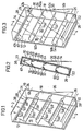
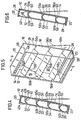
- the solar energy collectors illustrated in Figures 1 through 6 each comprise an enclosure 10, having a cover member 12, a base member 14, side members 16 and 18 and top and bottom members 20 and 22, all of which are fastened together in boxlike fashion by conventional means.
- Enclosure 10 is sealed such that it is substantially airtight except for fluid inlet port 24 and fluid outlet port 26 which are, respectively, openings in side 14 of the enclosure.
- the fluid inlet port is designed to be connected to a supply conduit which, in turn, is connected to a source of fluid.
- the fluid outlet port 26 is designed to be connected to a fluid return conduit.
- fluid such as water or the like is pumped through the supply conduit into inlet port 24.
- the fluid flows, by means of gravity, through enclosure 10 from the top thereof to the bottom thereof at which is located a collection trough 28.
- a collection trough 28 empties into fluid outlet 26 such that the fluid travels through a return pipe to a heat exchanger. In the heat exchanger the heat energy which was captured by the fluid, as it flowed through the enclosure, is removed and utilized for purposes such as heating or the like.
- Cover member 12 has solar energy transmitting properties and, thus, permits the passage of light from the sun therethrough.
- Cover member 12 can be made of any light transmitting material, preferably transparent in nature, such as glass or plastic. More specifically, cover member 12 can be made of a single or multiple panes of glass, a rigid sheet or sheets of plastic or a relatively flexible sheet or sheets of plastic which are maintained in a taut state by the structure which mounts same to sides 14 and 16, top 20 and bottom 22 of enclosure 10.
- Base member 14 is composed of a noncorrosive material, such as aluminum or the like, and is provided on its interior surface 30 with an energy absorbing coating of black paint or the like. Energy absorbing surface 30 of base member 14 is spaced from the interior surface 32 of cover member 12 so as to provide an air space therebetween.
- the rear or exterior surface of base member 14 is preferably provided with a layer of insulating material 34 composed of plastic, mineral wool, or other heat insulating substance which is affixed to the rear or exterior surface of base member 14 by any suitable means such as adhesive or the like.
- the enclosure For the proper operation of the collector, the enclosure must be inclined with respect to the horizontal at an angle such that adhesion forces between the fluid and surface 32 are greater than the gravitational forces on the fluid. This will permit a thin stream or film of fluid to flow along surface 32 of cover member 12, from the top to the bottom thereof, without dripping off.
- the angle of inclination of the enclosure must be such that fluid dispensed to the upper portion of the interior surface 32 of cover member 12 will run down along the surface to collecting member 28.
- cover member 12 is made of plastic or glass and has a substantially planar interior surface 32, water or other similar fluid will adhere to the surface as long as same is not inclined with respect to the horizontal at an angle less than 30°.
- the surface is inclined with respect to the horizontal at an angle greater than 30°, at least a substantial portion of the water flowing over the surface will tend to adhere to or cling to the surface as it is caused by gravity to flow to the bottom thereof. This is particularly true when means are provided to evenly distribute the stream or film of water along the surface.
- fluids having other properties may require that the enclosure be inclined within a different range of angles with respect to the horizontal.
- the appropriate range of angles of inclination with respect to the horizontal to be used with any particular fluid can easily be determined by one skilled in the art through routine experimentation.
- Enclosure 10 may be designed for freestanding use, such as in a garden or on top of a horizontal roof or may be designed for mounting on an inclined roof.
- a stand 36 or other suitable support means connected to the rear of the enclosure may be employed.
- the enclosure may be affixed directly to the roof by suitable mounting structure with the rear surface adjacent the roof. In this instance, it is also possible, to design the enclosure to be a part of the roof itself with the exterior surface of the roof itself being substituted for base member 14.
- the enclosure is designed for use on an inclined roof which does not have a suitable angle of inclination, appropriate mounting means must be provided such that the enclosure is mounted to the roof in a manner which orientates same at an appropriate angle with respect to the horizontal.
- appropriate support means, or mounting means which is utilized in conjunction with the enclosure forms no portion of the present invention and is of the type of structure which would routinely be designed by one skilled in the art in accordance with the mounting requirement for a particular application.
- fluid enters the top of the enclosure and flows along the energy absorbing surface of the base member, by means of gravity, and is collected at a trough or the like located at the bottom of the enclosure.
- Sunlight travels through the cover member, hits the energy absorbing surface of the base member and heats same.
- the fluid as it flows over the energy absorbing surface of the base member, captures the heat energy therefrom and transfers same to an energy extracting device such as a heat exchanger.
- the air within the enclosure is normally saturated and, thus, has a relatively high vapor pressure.
- the high vapor pressure will normally result in vapor leakage from the enclosure if same is not sealed to a very high degree. Leakage of vapor results in heat loss because the leaking vapor contains heat of evaporation.
- One of the main features of the present invention is to provide a solar heat collector, substantially as described above, with a means of washing the interior surface 32 of cover member 12 to remove the condensation and to capture the heat therefrom. In this manner, the heat on the cover member can be utilized effectively. In doing so, the vapor pressure within the enclosure is substantially reduced thereby diminishing the amount of vapor which escapes. Reduction of the vapor pressure within the enclosure reduces heat loss and also reduces the criticality of the sealing structure utilized and, thus, permits less expensive enclosures to be designed.
- Washing of the interior surface 32 of cover member 12 is accomplished by causing a thin stream or continuous film or fluid to flow along interior surface 32. This result may be accomplished by one of several different structures. It is preferable, although not necessary, that the structure which is utilized to cause the stream of fluid to flow along the interior surface of the cover member be the same structure which is utilized to impart a flow of fluid along the energy absorbing surface of the base member.
- the means for causing a stream of fluid to flow along interior surface 32 of cover member 12 may take the form of a means for spraying fluid onto the interior surface 32 of cover member 12, as is illustrated in the embodiment shown in Figures 1 and 2, as well as the embodiment shown in Figures 5 and 6.
- An alternate means for causing a stream of fluid to flow along interior surface 32 of cover member 12 is illustrated by the fluid dispensing means shown in the embodiment of Figures 3 and 4.
- the fluid spraying means comprises a tube or conduit 38 which has one end thereof connected to inlet port 24 and the other end thereof sealed.
- conduit 38 along the length of conduit 38, on the portion thereof facing interior surface 32 of cover member 12, are a set of openings or apertures 40.
- the fluid passes through apertures 40 such that it is sprayed on the interior surface 32 of cover member 12.
- the spray creates a stream or film of fluid which flows along the interior surface 32, because of gravity, until it reaches the collection trough 28 located at the bottom of the enclosure.
- the fluid stream flows along interior surface 32, it removes the condensation thereon and captures heat energy from the cover member.
- the fluid is collected in trough 28 which, in turn, is connected to the return pipe through fluid outlet port 26.
- the stream causing means is a fluid dispensing means in the form of a dispensing member 42 which is mounted on, and extends from, the interior surface 30 of base member 14 toward interior surface 32 of cover member 12.
- Member 42 when viewed edgewise ( Figure 4), has a substantially inverted "check" shape.
- the exterior edge 44 of member 42 is in close proximity, but spaced a small distance from, interior surface 32 of cover member 12.
- the longer section 42a' of member 42 forms, with the portion of surface 30 adjacent thereto, a temporary fluid retaining means or trough which will serve to collect fluid therebetween.
- This retaining means is adjacent fluid inlet port 24 such that as fluid passes through fluid inlet port 24, it will collect between portion 42a of member 42 and the adjacent portion of surface 30 until sufficient fluid is collected to cause the fluid to run over the apex of member 42 between portion 42a and 42b. After the fluid flows over the apex between portions 42a and 42b of member 42, it will run along the surface of portion 42b to edge 44 which is in close proximity to, but spaced from, the interior surface 32. Because edge 44 is in close proximity to interior surface 32, edge 44 will act as a fluid outlet means which will dispense fluid onto the interior surface 32 in a thin stream or film. As before, the thin stream or film or fluid will adhere to the interior surface 32 as it is caused, by gravity, to travel therealong to the bottom of interior surface 32 and, thus, be collected in trough 28.
- the means for causing a stream of fluid to flow along the interior surface 32 of cover member 12 is preferably utilized in conjunction with a means for imparting a flow of fluid to the energy absorbing surface 30 of base member 14.
- this spraying means can be conveniently utilized to impart the flow of fluid along surface 30 by simply creating a second set of apertures or holes 46 ( Figure 2) facing surface 30 such that the fluid introduced into conduit 38 under pressure not only sprays through apertures 40 onto the interior surface 32, but also simultaneously sprays through apertures 46 onto interior surface 30.
- a means for imparting a flow of fluid to energy absorbing surface 30 can be created simply by forming one or more openings or apertures 48 along the junction between portion 42a of member 40 and the energy absorbing surface 30, such that a portion of the fluid which is retained temporarily therebetween will exit at the bottom thereof and flow along the energy absorbing surface 30.
- the distribution means may comprise a plurality of members, identical in structure and function to dispensing member 42, which are situated in substantially transverse relationship to the fluid flow.
- Each of the members has a portion 50a connected to, and extending from surface 30 with a number of apertures or holes 52 at the junction therebetween.
- Each of the portions 50a meets surface 30 in a manner to temporarily retain fluid therebetween, such that same can exit through apertures 52 in a relatively even distribution across surface 30.
- Each of the members also has a portion 50b with an edge 54 which extends in close proximity to, but is spaced from, interior surface 32 and which serves to evenly distribute the stream or film of fluid across surface 32.
- the distribution means takes the form of a plurality of members which when viewed edgewise ( Figure 6), appear to have an inverted "V"- shape.
- the members extend from interior surface 30 to interior surface 32 such that two fluid retaining troughs, one situated between portion 56a and surface 30, and one situated between portion 56b and surface 32, are created.
- a series of apertures 58 and 60 distributed evenly across the length of the member which permit fluid temporarily retained in the trough to be evenly distributed along the adjacent interior surface.
- the distribution means may also take the form shown in Figures 1 and 2.
- the distribution means comprise planar members 62 and/or 64 which extend inwardly and at an acute angle from surface 30 or 32 and have a series of outlets or apertures 66, 68, respectively, along the bottom thereof.
- Members 62 and 64 function in the identical manner as said distributing members, but comprise separate members instead of a single member with a structure such as said member.
- the distribution means serve a dual purpose. First, they tend to slow down the fluid flow through the enclosure such that more heat may be absorbed thereby. Second, they spread the fluid more evenly over the interior surfaces such that more heat energy may be absorbed by the fluid.
- FIG. 7 is a schematic diagram illustrating the manner in which a plurality of enclosures 10 could be utilized in a residential hot water heating system.
- a plurality of enclosures 10, four of which are shown, are mounted on the roof of a house, the roof having the appropriate angle of inclination.
- Each of the inlet ports 24 are connected to a supply conduit 70, preferably formed of plastic pipe.
- Supply conduit 70 is fed by an electric pump 72 which may be continuously operated but which is preferably actuated by a thermostatic control 74 located adjacent the energy absorbing surface of the base member of one of the enclosures 10.
- Thermostat 72 is set to actuate circulation pump 72 when the temperature of the energy absorbing surface adjacent thereto reaches a first predetermined level and to deactuate circulation pump 72 when the temperature reaches a second predetermined level, lower than the first predetermined level.
- a timing circuit (not shown) may be employed.
- each of the enclosures 10 are connected to a return conduit 76 which feeds a heat exchanger coil 78 located in an insulated water storage tank or accumulator 80 which feeds the radiator system and heats a domestic hot water heater, both of which are not shown.
- Fluid from the heat exchanger 78 is then directed, by means of conduit 82, to a tank or reservoir 84, which in turn, feeds circulation pump 72.
- Tank or reservoir 84 preferably has sufficient capacity to contain all of the fluid in the system, such that the system can be drained to avoid freezing.
- the solar energy collector of the present invention has greatly improved efficiency of operation, as compared with conventional solar energy collectors of this type.
- the increased efficiency of operation is a result of the washing of the interior surface of the cover member to remove fluid condensation and to capture the energy thereon.
- the removal of the condensation on the interior surface of the cover member permits a high degree of light from the sun, which reaches the collector, to hit the energy absorbing surface of the base member.
- the capture of the heat energy in the cover member, imparted thereto by the passage therethrough of light from the sun and from the heat of evaporation of the condensed fluid permits use of this heat which would normally be lost to the environment.
- removal of the condensation reduces the vapor pressure from within the enclosure so as to reduce vapor leaks and, thus, loss of the heat of evaporation therein.
- the means for washing the interior surface of the cover member is preferably utilized in conjunction with a means for imparting flow along the energy absorbing surface of the base member.
- Distribution means are preferably provided to insure even distribution of the fluid across the interior surfaces of the enclosure to decrease the speed of flow and increase the amount of surface area over which the fluid flows.
- collectors of the present invention can be manufactured and installed and operated for approximately the same costs as conventional solar energy collectors of this type.
- the energy absorbing member such as member 30 only consists of a single plate which is directly heated by the sun.
- the effect of the solar energy collector can be further increased by positioning an additional absorbing plate (not shown) in parallel between the glass and the member 30.
- This absorbing plate divides the enclosure 10 into two separated air spces which, however, are air connected by air gaps at top and bottom edges of the additional plate.
- the additional plate and the air space between this plate and the glass are first heated. In the beginning are on the other hand the other air and the member 30 cold.
- the heat stored in the absorbing member 30 and the additional plate can thereafter in periods and intermittently be transferred to the circulating water by supplying such water principally in the same manner as described above to the top of the solar collector and allowing the water to flow downwardly along the heated member 30 and the additional plate as well as the interior surface of the glass and/or under the additional plate.
- the efficiency of the solar collector can be further increased.
- the energy absorbing surface can be partly or totally covered with so called solar cells, from which electric energy can be collected and utilized.
- the solar cells can by glueing or by some kind of fastening means be mounted on the absorbing plate and the electric energy can via a liquid-resistant electric line be transmitted to a battery or another electric energy can via a liquid-resistant electric radiation, electric energy is formed in the solar cells. However, about 80% of the solar energy will be converted into heat, thereby heating the solar cells.
- the heat energy absorbed by the solar cells can be utilized in the same manner as described above, wherein electric energy as well as heated liquid-for instance for house heating-can be obtained. The efficiency can thereby be essentially increased.
Landscapes
- Engineering & Computer Science (AREA)
- Mechanical Engineering (AREA)
- Physics & Mathematics (AREA)
- Sustainable Development (AREA)
- Sustainable Energy (AREA)
- Thermal Sciences (AREA)
- Chemical & Material Sciences (AREA)
- Life Sciences & Earth Sciences (AREA)
- General Engineering & Computer Science (AREA)
- Combustion & Propulsion (AREA)
- Photovoltaic Devices (AREA)
- Physical Or Chemical Processes And Apparatus (AREA)
- Buildings Adapted To Withstand Abnormal External Influences (AREA)
- Vaporization, Distillation, Condensation, Sublimation, And Cold Traps (AREA)
- Secondary Cells (AREA)
- Building Environments (AREA)
Priority Applications (1)
| Application Number | Priority Date | Filing Date | Title |
|---|---|---|---|
| AT79901221T ATE3671T1 (de) | 1978-10-06 | 1979-10-04 | Sonnenenergie-kollektor. |
Applications Claiming Priority (2)
| Application Number | Priority Date | Filing Date | Title |
|---|---|---|---|
| SE7810462 | 1978-10-06 | ||
| SE7810462A SE415926B (sv) | 1978-10-06 | 1978-10-06 | Anordning vid dubbelverkande solfangare |
Publications (2)
| Publication Number | Publication Date |
|---|---|
| EP0020440A1 EP0020440A1 (en) | 1981-01-07 |
| EP0020440B1 true EP0020440B1 (en) | 1983-06-01 |
Family
ID=20336017
Family Applications (1)
| Application Number | Title | Priority Date | Filing Date |
|---|---|---|---|
| EP79901221A Expired EP0020440B1 (en) | 1978-10-06 | 1979-10-04 | Solar energy collector |
Country Status (10)
| Country | Link |
|---|---|
| US (1) | US4261337A (da) |
| EP (1) | EP0020440B1 (da) |
| CA (1) | CA1134693A (da) |
| DE (1) | DE2965578D1 (da) |
| DK (1) | DK150411C (da) |
| ES (1) | ES484742A1 (da) |
| FI (1) | FI67948C (da) |
| NO (1) | NO149678C (da) |
| SE (1) | SE415926B (da) |
| WO (1) | WO1980000744A1 (da) |
Families Citing this family (3)
| Publication number | Priority date | Publication date | Assignee | Title |
|---|---|---|---|---|
| JPS58113400A (ja) * | 1981-12-28 | 1983-07-06 | Nippon Light Metal Co Ltd | アルミニウム電解着色排水の有効成分の回収法 |
| CN108662797B (zh) * | 2018-04-28 | 2020-01-21 | 上海理工大学 | 储热式平板型太阳能集热器 |
| US11732928B1 (en) * | 2019-09-09 | 2023-08-22 | Heliogen Holdings, Inc. | Gas receiver for capturing solar energy |
Family Cites Families (22)
| Publication number | Priority date | Publication date | Assignee | Title |
|---|---|---|---|---|
| US2843536A (en) * | 1952-05-10 | 1958-07-15 | James L Buckley | Solar still with means to clean evaporator surface |
| FR1168575A (fr) * | 1957-02-12 | 1958-12-10 | Centre Nat Rech Scient | Dispositif pour la culture intensive dans des régions arides et ensoleillées |
| US3513828A (en) * | 1968-11-04 | 1970-05-26 | Walter F Masters | Solar water heater |
| US4004380A (en) * | 1972-11-07 | 1977-01-25 | Kwake John P | Double walled inflatable structures |
| DE2419099A1 (de) | 1974-04-20 | 1975-11-20 | Wilhelm Mueller | Energie-gewinnungs-speicher und verbrauchersystem fuer wohn und aehnliche zwecke |
| US3939818A (en) * | 1974-04-23 | 1976-02-24 | Solar Energy Company | Solar energy heating module and assembly |
| US4018211A (en) * | 1974-05-01 | 1977-04-19 | Aai Corporation | Solar energy collection and transfer arrangement and method, and method of assembly |
| US3943911A (en) * | 1974-05-31 | 1976-03-16 | Yu Ying Nien | Solar heat collector |
| US3894528A (en) * | 1974-06-25 | 1975-07-15 | Broyles & Broyles Inc | Solar energy collection method and apparatus |
| US4003365A (en) * | 1974-09-23 | 1977-01-18 | Solar Energy Research Corporation | Structure for collecting solar energy |
| US3991742A (en) * | 1975-01-09 | 1976-11-16 | Burke Industries, Inc. | Solar energy heat transfer system |
| US4029081A (en) * | 1975-11-14 | 1977-06-14 | Strong John D | Solar energy transport system |
| US4124020A (en) * | 1976-01-05 | 1978-11-07 | Noble Haven D | Apparatus for collecting solar energy |
| US4121568A (en) * | 1976-04-20 | 1978-10-24 | James Percival Olsen | Solar panel flat plate collector |
| US4079726A (en) * | 1976-04-23 | 1978-03-21 | Percy Voelker | System for storage and use of solar energy |
| US4116220A (en) * | 1976-04-27 | 1978-09-26 | David Miller Burd | Solar energy collector |
| US4099559A (en) * | 1976-05-10 | 1978-07-11 | Olin Corporation | Solar absorber plate design |
| US4085732A (en) * | 1976-06-07 | 1978-04-25 | Hysom Ervin E | Method and apparatus for heating a liquid using solar energy |
| DE2626902A1 (de) * | 1976-06-16 | 1977-12-22 | Rainer Ing Grad Freilaender | Grossflaechen-sonnendestillationsanlage und beregnungsanlage |
| DE2748424A1 (de) * | 1977-10-28 | 1979-05-03 | Hermann Starkert | Schwimmbecken-kunststoffdach zur erwaermung des wassers unter ausnutzung der sonnenstrahlen |
| US4141498A (en) * | 1977-10-31 | 1979-02-27 | Walter Marschner | Combination structure and greenhouse utilizing indirect solar energy |
| FR2422323A1 (fr) * | 1978-04-13 | 1979-11-09 | Commissariat Energie Atomique | Procede de climatisation de serres a l'aide d'une eau non douce et de distillation de cette eau et installation en faisant application |
-
1978
- 1978-10-06 SE SE7810462A patent/SE415926B/sv not_active IP Right Cessation
-
1979
- 1979-03-09 US US06/019,290 patent/US4261337A/en not_active Expired - Lifetime
- 1979-03-23 CA CA000324063A patent/CA1134693A/en not_active Expired
- 1979-10-03 NO NO793180A patent/NO149678C/no unknown
- 1979-10-04 WO PCT/SE1979/000201 patent/WO1980000744A1/en not_active Ceased
- 1979-10-04 DE DE7979901221T patent/DE2965578D1/de not_active Expired
- 1979-10-04 ES ES484742A patent/ES484742A1/es not_active Expired
- 1979-10-04 EP EP79901221A patent/EP0020440B1/en not_active Expired
- 1979-10-05 FI FI793096A patent/FI67948C/fi not_active IP Right Cessation
-
1980
- 1980-06-04 DK DK241480A patent/DK150411C/da not_active IP Right Cessation
Also Published As
| Publication number | Publication date |
|---|---|
| NO149678B (no) | 1984-02-20 |
| EP0020440A1 (en) | 1981-01-07 |
| CA1134693A (en) | 1982-11-02 |
| WO1980000744A1 (en) | 1980-04-17 |
| FI67948C (fi) | 1985-06-10 |
| SE415926B (sv) | 1980-11-10 |
| NO149678C (no) | 1984-05-30 |
| FI793096A7 (fi) | 1980-04-07 |
| NO793180L (no) | 1980-04-09 |
| DK150411B (da) | 1987-02-23 |
| US4261337A (en) | 1981-04-14 |
| ES484742A1 (es) | 1980-06-16 |
| DK150411C (da) | 1987-09-28 |
| DK241480A (da) | 1980-06-04 |
| FI67948B (fi) | 1985-02-28 |
| SE7810462L (sv) | 1980-04-07 |
| DE2965578D1 (en) | 1983-07-07 |
Similar Documents
| Publication | Publication Date | Title |
|---|---|---|
| US4513732A (en) | Passive integral solar heat collector system | |
| US4074705A (en) | Solar collector apparatus and method | |
| US3996919A (en) | System for collecting and storing solar energy | |
| US4505261A (en) | Modular passive solar heating system | |
| US3145707A (en) | Solar heat collector | |
| US4117831A (en) | Energy collector for collecting solar energy and the like | |
| US4323054A (en) | Solar energy collection system | |
| US4073284A (en) | Process and device for utilizing meteorological radiations | |
| US4517958A (en) | Heat exchange system | |
| US4182406A (en) | Solar energy system for heating and cooling of buildings utilizing moist air cycles | |
| US4408596A (en) | Heat exchange system | |
| CN107176639B (zh) | 一种加湿冷凝式海水淡化装置 | |
| US4296741A (en) | Solar energy collecting panel assembly | |
| US4749447A (en) | Evacuated evaporation-pressurized condensation solar still | |
| CA2312116A1 (en) | Liquid desiccant dehumidifier and air conditioner | |
| US4280333A (en) | Passive environmental temperature control system | |
| US4124020A (en) | Apparatus for collecting solar energy | |
| US4261337A (en) | Solar energy collector | |
| US4556100A (en) | Thermal energy storage unit | |
| US9677786B2 (en) | Open-flow solar collector | |
| US5088471A (en) | Solar heating structure | |
| US20240263841A1 (en) | Solar thermal collector | |
| SE432661B (sv) | Rumsuppvermning med vermepump | |
| US4084575A (en) | Solar heater unit | |
| EP0015017A1 (en) | Heat transport tube solar collector and system comprising at least such a collector |
Legal Events
| Date | Code | Title | Description |
|---|---|---|---|
| PUAI | Public reference made under article 153(3) epc to a published international application that has entered the european phase |
Free format text: ORIGINAL CODE: 0009012 |
|
| 17P | Request for examination filed |
Effective date: 19801006 |
|
| AK | Designated contracting states |
Designated state(s): AT CH DE FR GB NL |
|
| GRAA | (expected) grant |
Free format text: ORIGINAL CODE: 0009210 |
|
| AK | Designated contracting states |
Designated state(s): AT CH DE FR GB NL |
|
| REF | Corresponds to: |
Ref document number: 3671 Country of ref document: AT Date of ref document: 19830615 Kind code of ref document: T |
|
| REF | Corresponds to: |
Ref document number: 2965578 Country of ref document: DE Date of ref document: 19830707 |
|
| EL | Fr: translation of claims filed | ||
| PLBE | No opposition filed within time limit |
Free format text: ORIGINAL CODE: 0009261 |
|
| STAA | Information on the status of an ep patent application or granted ep patent |
Free format text: STATUS: NO OPPOSITION FILED WITHIN TIME LIMIT |
|
| 26N | No opposition filed | ||
| PGFP | Annual fee paid to national office [announced via postgrant information from national office to epo] |
Ref country code: CH Payment date: 19840903 Year of fee payment: 6 |
|
| PGFP | Annual fee paid to national office [announced via postgrant information from national office to epo] |
Ref country code: FR Payment date: 19840926 Year of fee payment: 6 |
|
| PGFP | Annual fee paid to national office [announced via postgrant information from national office to epo] |
Ref country code: DE Payment date: 19841026 Year of fee payment: 6 |
|
| PGFP | Annual fee paid to national office [announced via postgrant information from national office to epo] |
Ref country code: AT Payment date: 19861015 Year of fee payment: 8 |
|
| PGFP | Annual fee paid to national office [announced via postgrant information from national office to epo] |
Ref country code: NL Payment date: 19871031 Year of fee payment: 9 |
|
| PG25 | Lapsed in a contracting state [announced via postgrant information from national office to epo] |
Ref country code: GB Effective date: 19891004 Ref country code: AT Effective date: 19891004 |
|
| PG25 | Lapsed in a contracting state [announced via postgrant information from national office to epo] |
Ref country code: CH Effective date: 19891031 |
|
| PG25 | Lapsed in a contracting state [announced via postgrant information from national office to epo] |
Ref country code: NL Effective date: 19900501 |
|
| GBPC | Gb: european patent ceased through non-payment of renewal fee | ||
| NLV4 | Nl: lapsed or anulled due to non-payment of the annual fee | ||
| PG25 | Lapsed in a contracting state [announced via postgrant information from national office to epo] |
Ref country code: FR Effective date: 19900629 |
|
| REG | Reference to a national code |
Ref country code: CH Ref legal event code: PL |
|
| PG25 | Lapsed in a contracting state [announced via postgrant information from national office to epo] |
Ref country code: DE Effective date: 19900703 |
|
| REG | Reference to a national code |
Ref country code: FR Ref legal event code: ST |
|
| P01 | Opt-out of the competence of the unified patent court (upc) registered |
Effective date: 20230522 |