EP0020594B1 - Abwärme-gasturbine - Google Patents
Abwärme-gasturbine Download PDFInfo
- Publication number
- EP0020594B1 EP0020594B1 EP79901563A EP79901563A EP0020594B1 EP 0020594 B1 EP0020594 B1 EP 0020594B1 EP 79901563 A EP79901563 A EP 79901563A EP 79901563 A EP79901563 A EP 79901563A EP 0020594 B1 EP0020594 B1 EP 0020594B1
- Authority
- EP
- European Patent Office
- Prior art keywords
- steam
- gas
- turbine
- reheat
- combustor
- Prior art date
- Legal status (The legal status is an assumption and is not a legal conclusion. Google has not performed a legal analysis and makes no representation as to the accuracy of the status listed.)
- Expired
Links
- 238000001816 cooling Methods 0.000 claims abstract description 38
- 238000003303 reheating Methods 0.000 claims abstract description 16
- XLYOFNOQVPJJNP-UHFFFAOYSA-N water Substances O XLYOFNOQVPJJNP-UHFFFAOYSA-N 0.000 claims abstract description 15
- 238000000034 method Methods 0.000 claims abstract description 12
- 230000008569 process Effects 0.000 claims abstract description 9
- 239000000446 fuel Substances 0.000 claims description 35
- 230000001133 acceleration Effects 0.000 claims description 11
- 238000000926 separation method Methods 0.000 claims description 4
- 239000012080 ambient air Substances 0.000 claims description 3
- 239000007788 liquid Substances 0.000 claims description 3
- 238000004519 manufacturing process Methods 0.000 claims description 3
- 230000003068 static effect Effects 0.000 claims description 2
- 239000007789 gas Substances 0.000 abstract description 158
- 238000010304 firing Methods 0.000 abstract description 12
- 230000008901 benefit Effects 0.000 abstract description 9
- 230000004888 barrier function Effects 0.000 abstract description 6
- 230000015556 catabolic process Effects 0.000 abstract description 3
- 238000006731 degradation reaction Methods 0.000 abstract description 3
- 238000005516 engineering process Methods 0.000 abstract description 3
- 238000002485 combustion reaction Methods 0.000 description 18
- 239000003570 air Substances 0.000 description 15
- 238000011084 recovery Methods 0.000 description 15
- 238000013459 approach Methods 0.000 description 5
- 239000003245 coal Substances 0.000 description 4
- 239000002826 coolant Substances 0.000 description 4
- 230000000694 effects Effects 0.000 description 4
- 230000004907 flux Effects 0.000 description 4
- 238000010438 heat treatment Methods 0.000 description 4
- 238000002156 mixing Methods 0.000 description 4
- 230000005068 transpiration Effects 0.000 description 4
- 239000000567 combustion gas Substances 0.000 description 3
- 238000009792 diffusion process Methods 0.000 description 3
- 238000000605 extraction Methods 0.000 description 3
- 230000005855 radiation Effects 0.000 description 3
- 239000007787 solid Substances 0.000 description 3
- 238000012546 transfer Methods 0.000 description 3
- 238000004458 analytical method Methods 0.000 description 2
- 230000008859 change Effects 0.000 description 2
- 238000010276 construction Methods 0.000 description 2
- 238000013461 design Methods 0.000 description 2
- 238000010586 diagram Methods 0.000 description 2
- 238000009987 spinning Methods 0.000 description 2
- 238000003860 storage Methods 0.000 description 2
- 238000010521 absorption reaction Methods 0.000 description 1
- 230000006978 adaptation Effects 0.000 description 1
- 230000000712 assembly Effects 0.000 description 1
- 238000000429 assembly Methods 0.000 description 1
- 230000004323 axial length Effects 0.000 description 1
- 238000009954 braiding Methods 0.000 description 1
- 239000000919 ceramic Substances 0.000 description 1
- 229910010293 ceramic material Inorganic materials 0.000 description 1
- 238000006243 chemical reaction Methods 0.000 description 1
- 238000004140 cleaning Methods 0.000 description 1
- 230000006835 compression Effects 0.000 description 1
- 238000007906 compression Methods 0.000 description 1
- 238000009833 condensation Methods 0.000 description 1
- 230000005494 condensation Effects 0.000 description 1
- 238000005260 corrosion Methods 0.000 description 1
- 230000007797 corrosion Effects 0.000 description 1
- 238000011161 development Methods 0.000 description 1
- 230000018109 developmental process Effects 0.000 description 1
- 238000007599 discharging Methods 0.000 description 1
- 238000009826 distribution Methods 0.000 description 1
- 238000001704 evaporation Methods 0.000 description 1
- 230000008020 evaporation Effects 0.000 description 1
- 238000007667 floating Methods 0.000 description 1
- 239000012530 fluid Substances 0.000 description 1
- 239000008240 homogeneous mixture Substances 0.000 description 1
- 238000010348 incorporation Methods 0.000 description 1
- 238000002347 injection Methods 0.000 description 1
- 239000007924 injection Substances 0.000 description 1
- 238000009413 insulation Methods 0.000 description 1
- 239000012212 insulator Substances 0.000 description 1
- 238000012423 maintenance Methods 0.000 description 1
- 238000012856 packing Methods 0.000 description 1
- 230000002093 peripheral effect Effects 0.000 description 1
- 238000004064 recycling Methods 0.000 description 1
- 230000008929 regeneration Effects 0.000 description 1
- 238000011069 regeneration method Methods 0.000 description 1
- 230000000630 rising effect Effects 0.000 description 1
- 229920006395 saturated elastomer Polymers 0.000 description 1
- 239000004449 solid propellant Substances 0.000 description 1
- 238000006467 substitution reaction Methods 0.000 description 1
- 230000003746 surface roughness Effects 0.000 description 1
- 238000005496 tempering Methods 0.000 description 1
Images


Classifications
-
- F—MECHANICAL ENGINEERING; LIGHTING; HEATING; WEAPONS; BLASTING
- F02—COMBUSTION ENGINES; HOT-GAS OR COMBUSTION-PRODUCT ENGINE PLANTS
- F02C—GAS-TURBINE PLANTS; AIR INTAKES FOR JET-PROPULSION PLANTS; CONTROLLING FUEL SUPPLY IN AIR-BREATHING JET-PROPULSION PLANTS
- F02C6/00—Plural gas-turbine plants; Combinations of gas-turbine plants with other apparatus; Adaptations of gas-turbine plants for special use
- F02C6/18—Plural gas-turbine plants; Combinations of gas-turbine plants with other apparatus; Adaptations of gas-turbine plants for special use using the waste heat of gas-turbine plants outside the plants themselves, e.g. gas-turbine power heat plants
-
- F—MECHANICAL ENGINEERING; LIGHTING; HEATING; WEAPONS; BLASTING
- F01—MACHINES OR ENGINES IN GENERAL; ENGINE PLANTS IN GENERAL; STEAM ENGINES
- F01D—NON-POSITIVE DISPLACEMENT MACHINES OR ENGINES, e.g. STEAM TURBINES
- F01D5/00—Blades; Blade-carrying members; Heating, heat-insulating, cooling or antivibration means on the blades or the members
- F01D5/12—Blades
- F01D5/14—Form or construction
- F01D5/18—Hollow blades, i.e. blades with cooling or heating channels or cavities; Heating, heat-insulating or cooling means on blades
- F01D5/185—Liquid cooling
-
- F—MECHANICAL ENGINEERING; LIGHTING; HEATING; WEAPONS; BLASTING
- F01—MACHINES OR ENGINES IN GENERAL; ENGINE PLANTS IN GENERAL; STEAM ENGINES
- F01D—NON-POSITIVE DISPLACEMENT MACHINES OR ENGINES, e.g. STEAM TURBINES
- F01D5/00—Blades; Blade-carrying members; Heating, heat-insulating, cooling or antivibration means on the blades or the members
- F01D5/12—Blades
- F01D5/14—Form or construction
- F01D5/18—Hollow blades, i.e. blades with cooling or heating channels or cavities; Heating, heat-insulating or cooling means on blades
- F01D5/187—Convection cooling
-
- F—MECHANICAL ENGINEERING; LIGHTING; HEATING; WEAPONS; BLASTING
- F01—MACHINES OR ENGINES IN GENERAL; ENGINE PLANTS IN GENERAL; STEAM ENGINES
- F01K—STEAM ENGINE PLANTS; STEAM ACCUMULATORS; ENGINE PLANTS NOT OTHERWISE PROVIDED FOR; ENGINES USING SPECIAL WORKING FLUIDS OR CYCLES
- F01K23/00—Plants characterised by more than one engine delivering power external to the plant, the engines being driven by different fluids
- F01K23/02—Plants characterised by more than one engine delivering power external to the plant, the engines being driven by different fluids the engine cycles being thermally coupled
- F01K23/06—Plants characterised by more than one engine delivering power external to the plant, the engines being driven by different fluids the engine cycles being thermally coupled combustion heat from one cycle heating the fluid in another cycle
- F01K23/10—Plants characterised by more than one engine delivering power external to the plant, the engines being driven by different fluids the engine cycles being thermally coupled combustion heat from one cycle heating the fluid in another cycle with exhaust fluid of one cycle heating the fluid in another cycle
- F01K23/103—Plants characterised by more than one engine delivering power external to the plant, the engines being driven by different fluids the engine cycles being thermally coupled combustion heat from one cycle heating the fluid in another cycle with exhaust fluid of one cycle heating the fluid in another cycle with afterburner in exhaust boiler
-
- F—MECHANICAL ENGINEERING; LIGHTING; HEATING; WEAPONS; BLASTING
- F02—COMBUSTION ENGINES; HOT-GAS OR COMBUSTION-PRODUCT ENGINE PLANTS
- F02C—GAS-TURBINE PLANTS; AIR INTAKES FOR JET-PROPULSION PLANTS; CONTROLLING FUEL SUPPLY IN AIR-BREATHING JET-PROPULSION PLANTS
- F02C6/00—Plural gas-turbine plants; Combinations of gas-turbine plants with other apparatus; Adaptations of gas-turbine plants for special use
- F02C6/003—Gas-turbine plants with heaters between turbine stages
-
- F—MECHANICAL ENGINEERING; LIGHTING; HEATING; WEAPONS; BLASTING
- F02—COMBUSTION ENGINES; HOT-GAS OR COMBUSTION-PRODUCT ENGINE PLANTS
- F02C—GAS-TURBINE PLANTS; AIR INTAKES FOR JET-PROPULSION PLANTS; CONTROLLING FUEL SUPPLY IN AIR-BREATHING JET-PROPULSION PLANTS
- F02C7/00—Features, components parts, details or accessories, not provided for in, or of interest apart form groups F02C1/00 - F02C6/00; Air intakes for jet-propulsion plants
- F02C7/12—Cooling of plants
- F02C7/16—Cooling of plants characterised by cooling medium
-
- F—MECHANICAL ENGINEERING; LIGHTING; HEATING; WEAPONS; BLASTING
- F05—INDEXING SCHEMES RELATING TO ENGINES OR PUMPS IN VARIOUS SUBCLASSES OF CLASSES F01-F04
- F05D—INDEXING SCHEME FOR ASPECTS RELATING TO NON-POSITIVE-DISPLACEMENT MACHINES OR ENGINES, GAS-TURBINES OR JET-PROPULSION PLANTS
- F05D2240/00—Components
- F05D2240/20—Rotors
- F05D2240/30—Characteristics of rotor blades, i.e. of any element transforming dynamic fluid energy to or from rotational energy and being attached to a rotor
- F05D2240/302—Characteristics of rotor blades, i.e. of any element transforming dynamic fluid energy to or from rotational energy and being attached to a rotor characteristics related to shock waves, transonic or supersonic flow
-
- F—MECHANICAL ENGINEERING; LIGHTING; HEATING; WEAPONS; BLASTING
- F05—INDEXING SCHEMES RELATING TO ENGINES OR PUMPS IN VARIOUS SUBCLASSES OF CLASSES F01-F04
- F05D—INDEXING SCHEME FOR ASPECTS RELATING TO NON-POSITIVE-DISPLACEMENT MACHINES OR ENGINES, GAS-TURBINES OR JET-PROPULSION PLANTS
- F05D2260/00—Function
- F05D2260/20—Heat transfer, e.g. cooling
- F05D2260/202—Heat transfer, e.g. cooling by film cooling
-
- F—MECHANICAL ENGINEERING; LIGHTING; HEATING; WEAPONS; BLASTING
- F05—INDEXING SCHEMES RELATING TO ENGINES OR PUMPS IN VARIOUS SUBCLASSES OF CLASSES F01-F04
- F05D—INDEXING SCHEME FOR ASPECTS RELATING TO NON-POSITIVE-DISPLACEMENT MACHINES OR ENGINES, GAS-TURBINES OR JET-PROPULSION PLANTS
- F05D2260/00—Function
- F05D2260/20—Heat transfer, e.g. cooling
- F05D2260/232—Heat transfer, e.g. cooling characterized by the cooling medium
- F05D2260/2322—Heat transfer, e.g. cooling characterized by the cooling medium steam
-
- Y—GENERAL TAGGING OF NEW TECHNOLOGICAL DEVELOPMENTS; GENERAL TAGGING OF CROSS-SECTIONAL TECHNOLOGIES SPANNING OVER SEVERAL SECTIONS OF THE IPC; TECHNICAL SUBJECTS COVERED BY FORMER USPC CROSS-REFERENCE ART COLLECTIONS [XRACs] AND DIGESTS
- Y02—TECHNOLOGIES OR APPLICATIONS FOR MITIGATION OR ADAPTATION AGAINST CLIMATE CHANGE
- Y02E—REDUCTION OF GREENHOUSE GAS [GHG] EMISSIONS, RELATED TO ENERGY GENERATION, TRANSMISSION OR DISTRIBUTION
- Y02E20/00—Combustion technologies with mitigation potential
- Y02E20/16—Combined cycle power plant [CCPP], or combined cycle gas turbine [CCGT]
-
- Y—GENERAL TAGGING OF NEW TECHNOLOGICAL DEVELOPMENTS; GENERAL TAGGING OF CROSS-SECTIONAL TECHNOLOGIES SPANNING OVER SEVERAL SECTIONS OF THE IPC; TECHNICAL SUBJECTS COVERED BY FORMER USPC CROSS-REFERENCE ART COLLECTIONS [XRACs] AND DIGESTS
- Y02—TECHNOLOGIES OR APPLICATIONS FOR MITIGATION OR ADAPTATION AGAINST CLIMATE CHANGE
- Y02T—CLIMATE CHANGE MITIGATION TECHNOLOGIES RELATED TO TRANSPORTATION
- Y02T50/00—Aeronautics or air transport
- Y02T50/60—Efficient propulsion technologies, e.g. for aircraft
Definitions
- This invention relates generally to the production of useful power by means of a combined gas turbine and steam turbine cycle including reheating of exhaust gas formed in the first part of the gas turbine.
- a regenerator has been used to heat a compressor's discharge air to improve cycle efficiency, and intercooling has been suggested for the same purpose. It is known that reheating can increase power output by 35 to 40%. But without use of regeneration, overall cycle efficiency is degraded.
- the present invention provides apparatus for generating useful power comprising a compressor (24) wherein ambient air is compressed and then fed to a combustor (30) where it reacts with fuel to form a first gas which impels a gas turbine (28) and driving said compressor (24), gas exhausted from the gas turbine (28) passing to a diffuser (124,130) whence it passes to a reheat combustor (36) where it reacts with further fuel to produce a second gas which drives a power turbine (42), which mechanically powers a first electrical generator (44), and which exhausts a third gas which is fed to a heat exchanger (50) wherein the third gas is cooled and liquid water is heated to convert it to steam which drives a steam turbine (68) mechanically connected to a second electrical generator (70), characterised in that:-
- gas generator 20 receives ambient air through inlet line 22, producing compressed air by compressor 24, which is driven through shaft 26 by gas generator turbine 28, which is powered by gas produced in first combustor 30 to which compressed air is fed through line 32.
- Fuel enters combustor 30 through fuel line 34.
- Reheat or second combustor 36 receives high velocity exhaust from gas generator turbine 28 through reheat axial flow annular diffuser 38 and discharges reheated gas through axial flow annular acceleration duct 40 to power turbine 42, which drives first electric generator 44 directly by shaft 46.
- Reheat gas output leaves power turbine 42 through exit line 48 and passes into heat exchanger 50 prior to discharge through stack line 52.
- Exit gases through exit line 48 pass through three stages of heat exchanger 50, the first being superheater 54, where superheated steam is produced through superheat line 56; the second being evaporator 58, where water from storage drum 60 and combined recycled water is evaporated in line 62; and the third being economizer 64, where water from storage drum 60 and recycled water from line 66 is heated before being evaporated in line 62 of evaporator 58.
- economizer 64 recycled water entering from line 66 is warmed for evaporation in line 59 before entering evaporator 58.
- Superheated steam leaving superheater 54 through line 56 enters and drives steam turbine 68, which directly powers second electric generator 70 through shaft 72.
- Condensate from steam turbine 68 is formed and collected in condenser 76 and pumped by condenser pump 78 through line 80, along with steam formed directly in turbine 68, through line 82, to heater 86, the output of which is fed by boiler feed pump 88 to recycle line 66.
- first electric generator 44 being powered by two such arrangements, the reheat exhaust gas output of which feeds into exit line 48.
- each of the individual components of the system shown in Figure 1 with the exception of the diffuser reheat combustor and acceleration duct are conventional and only the combined arrangement including these three parts leading to the advantages and efficiencies disclosed in the present invention, are intended to be described as new. Steam cooling/injection, not shown in Figure 1, another part of this present invention is likewise considered new.
- gas generator 20 functions in the same manner as the gas generator described for Figure 1, and steam turbine 68, condenser 76, heater 86, and pumps 78 and 88 function in the same manner as in Figure 1.
- the output of gas generator 20 enters reheat combustor 90 through axial flow annular diffuser 38, reheat combustor 90 being, a combined reheat combustor and superheater, reheating exhaust gas from diffuser 38 of gas generator 20 and discharging reheated gas through axial flow annular acceleration duct 40 to drive power turbine 42, which drives first electric generator 44 by means of shaft 46.
- Reheat combustor 90 also superheats the output from evaporator 58, entering reheat combustor 90 through line 92 and leaving through line 56, for driving steam turbine 68. Reheating of steam also occurs in cavity 134 (see Figure 4), the steam entering cavity 134 through line 94 and leaving reheat combustor 90 through line 96 to enter steam turbine 68 at a stage downstream of the inlet from superheated steam line 56. Steam turbine 68 drives second electric generator 70 through shaft 72, and recycling of condensed output through line 66 occurs through economizer 64 and evaporator 58.
- FIG. 2 is a representation of gas generator 20 in association with reheat combustor 36, although gas generator 20 could also be associated with cavity 134 for performing both a reheat and steam superheating function. In either instance, a substantially linear axial flow of gas from gas generator 20 to power turbine. 42 is maintained.
- Gas generator 20 is made up of combustor 30 and air compressor 24, which has stages 100, 102 and 104, 106 and 108 of five-stage low pressure section, as well as stages 110 and 112, which are representative stages of a 14-stage high pressure section.
- Combustor 30 discharges compressed heated air to stages 114 and 116 of a two-stage high pressure section in gas turbine 28 and stage 118 of a one-stage low pressure section thereof.
- Shaft 26 connects compressor 24 with gas generator turbine 28.
- gas generator 20 in Figure 2 illustrating the second generation LM 5000 Model, other model designations currently available commercially including the LM 2500, JT 9, RB-211, Spey, and the Mars.
- Gas generator 20 in Figure 2 is coupled with reheat combustor 36, showing fuel line 35, fuel nozzle 120, annular combustion cavity and acceleration region 122, diffuser 124, and the power turbine 42. It is to be understood that a plurality of fuel nozzles 120, arranged concentrically produce the annular flow of reheat gas which drives power turbine 42.
- the output of gas generator 20 can feed reheat combustor 90 and cavity 134 shown in Figure 4, for performing both a reheat and a superheating function.
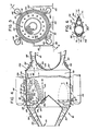
- Air from diffusion 130 passes around struts 132 and is heated in combustion cavity region 134 as fuel nozzle 136 discharges fuel for combustion therein.
- Fuel enters cavity 134 through fuel line 138 and is ignited by spark plug 140.
- Superheat and reheat helical tubing coils 142 are shown somewhat schematically in Figure 4, having the configuration of Figure 6 in enlarged detail.
- Boiler steam header 144 furnishes steam through line 92 to reheat combustor 90, and after boiler steam has traversed its helical path around and through cavity 134, it leaves reheat combustor 90 through line 56 for collection in boiler steam header 148.
- Reheat steam leaves reheat combustor 90 through reheat steam outlet line 96, entering reheat steam header 146.
- Reheat steam enters reheat combustor 90 through reheat steam inlet 94 from header 150.
- Insulation 152 surrounds reheat combustor 90, diffuser 130, headers 146, 148, 144 and 150, and also surrounds inlet power turbine acceleration duct 154.
- Exit gases pass through inlet nozzle 156 to drive turbine 42, passing next to power turbine first stage nozzle 156 as shown in Figure 4.
- the inside surface 157 of inlet duct 154 is in the shape of a nose of a bullet, while outside bell mouth 196 has the shape shown.
- Figure 6 shows stream-lined fabricated superheat tubing 142 containing perforated airfoil shaped extended surface sheath 158 surrounding three tube sections 160,162 and 164 for enclosing superheated and/or reheated steam, the respective diameters of the tube sections varying according to the flow rates and throughput demanded of each component.
- the sheathing provides streamlined section for gas directional control.
- the spacing between coils provides pressure drop and mass flow control.
- thermodynamic advantage and higher combined cycle efficiency obtained through a minimum stack temperature and three stages of feedwater heating made possible by the combined apparatus.
- a combined gas turbine reheat and steam turbine cycle with steam reheat generates an over-all power plant efficiency approaching or exceeding 50% LHV when burning the distillate fuel in the apparatus of Figure 4.
- Combustor 36 incorporates an annular liner 121 flaring outwardly to an axial flow annular acceleration duct 122 and then to an exit plane 170 at power turbine 42.
- Fuel nozzles 120 are disposed in liner 121 and have orifices 123 equally spaced on an orifice plane and separated by a chord width having a chord width diameter with respect to axis 172 of the entire arrangement.
- Fuel nozzles 120 are directed outwardly along a pitch line forming a pitch angle with respect to axis 172, the intersection of the pitch lines with exit plane 170 having a pitch line diameter in a certain preferred ratio to the chord diameter.
- the output gas at the exit plane of the gas generator combustor 30 has a temperature of approximately 2100°F (1149°C) and a pressure of approximately 30 atmospheres, while the exhaust gas at the orifice plane of the reheat combustor 36 has a temperature of approximately 1800°F (982°C) and 3.75 atmospheres. Accordingly, a volume ratio of 6.9 is obtained, and this value is preferably increased slightly to produce a lower pressure drop across combustor 36.
- the volume ratio of 6.9 translated to pitch line diameter ratio of the gas generator annular combustor outlet compared to the reheat combustor annular outlet is the square root of the volume ratio or approximately 2.63 which is clearly evidenced by referring to Figure 2 and comparing the diameter of blade 114 versus the diameter of outer nozzle diameter 170.
- This area ratio, or relative increase in annular combustor cavity 122 and 134 cross-sectional flow area then provides combustor 36 and 90 and cavity 122 and 134forward flow velocity equal to and preferred less than that of the gas generator combustor 30.
- the area ratio or relative increase in inlet area in front of combustor cap 155 and around the combustor liner 121 and around steam tubing 142 is calculated in the same manner to provide low approach and liner inlet velocities commensurate with low velocity-low pressure drop industrial type combustors, the total liner or steam coil pressure loss being about 2 to 2) percent and the approach velocities being about 100 feet per second (30 m/sec) or less for such industrial type combustors well known to those skilled in this art.
- diffuser 124 and_in the alternative apparatus, diffuser 130, Figure 4 has a length of at least four feet (1.2 metres) to prevent separation and resulting turbulence of incoming gas.
- the diffuser is shown somewhat schematically to reduce the drawing length, and the cross-sectional annular flow area change from the diffuser inlet to the diffuser outlet is shown to be about five. However, this is only a schematic representation and of course to achieve a lower exit velocity the area ratio of inlet to outlet would have to be greater on an actual machine.
- the required diameter of reheat combustor 90 is about 10 feet (3 m), which takes into account a gas velocity of about 100 feet per second (33 mm/s) and the increase in area required to accommodate superheater tubes 142, assuming an average gas temperature of about 2000°F (1093°C).
- the increase in area to accommodate tubes 142 is about 70%.
- the length of diffusor and reheat combustor 90 combined can vary somewhat according to the surface area required for superheating, and a workable length is about 18 feet (5,49 m).
- Outer shell 176 is fabricated in sections about two feet long and bolted together at joints 178 so that superheater coils 142 can be inserted properly.
- the outer shell 176 and associated pipes 56, 92, 94, 96, etc. can be disconnected from headers 144, 146, 148 and 150 at flanges 57, 93, 95, 97, etc., for removal of the two foot sections of outer shell 176.
- Superheater tubes 142 are wrapped around in a manner to form helical coils of specific configurations, such as that illustrated in Figure 6. Coils 142 form an annular combustion cavity 134 and control air flow to burner 136. Downstream from burner 136 coils 142 then temper hot combustion gases and distribute them through more coils 142. Combustion cap 155 for primary combustion air control can also be seen.
- cold steam enters at the bottom of reheat combustor 90, circulates through tubes 142 and then exits at the top for each superheater.
- Shell 176 can be center-line supported by supporting mounts 180 to control expansion and to maintain a reasonable center-line elevation with respect to foundation 182 and to satisfy axial alignment of gas generator 20 and power turbine 42.
- gas generator 20 can be quickly and readily removed to service reheat combustor 90.
- Tubes 142 are fabricated with three different sizes 160, 162 and 164, and are streamlined with perforated airfoil shaped overlays 158 to minimise pressure drop and control the hot gas flow as illustrated in Figure 6.
- the perforations allow proper temperature gas to enter and reach the surfaces of tubes 160, 162 and 164, thereby increasing considerably the effective heat transfer area.
- Diffuser 130 from gas generator 20 to reheat combustor 90 has an extra length, and the gas generator assisted by the angle of the struts 132 imparts a swirl to gas passing therethrough to give the gas a longer flow path to assist in diffusion of the gas entering cavity 134.
- Power turbine 42 has an inlet acceleration duct consisting of an outer cone or bell mouth 196 and inner bullet-shaped nose 157 to reduce inlet loss from cavity 90 to power turbine 42, where velocity of gas is increased.
- a longer diffuser is possible between the gas generator and second combustor. It should be stressed that it is the longer diffuser axial length that is important. This length makes it possible to provide a gradual angularity change and a gradual increase in annular diffuser diameter to make full diffusion possible with very little loss (friction).
- the outlet internal and external diameters can be adjusted as needed without space restriction for the industrial gas turbine.
- the total pressure loss in the diffuser and reheat combustor and acceleration duct all with an axial flow arrangement being part of this invention is assumed to be 3 percent as given in the assumption of Table II, line 7, where the combustor liner 121 or tubing 142 account for 2 to 2) percent of this total loss in accordance with known and established data for low velocity (100 feet/sec) (30 m/sec) or less industrial type combustors.
- reheat combustor 90 is apparent, leading to equal and even loop, that is, pressure vessel, stress.
- Coils 190 about the periphery of the inside of cavity 134 define and in effect form the combustion chamber thereof, and inside coils 190 serve as an insulator to shell 176.
- inner coils 142 are arranged about the reheat combustion cavity region 134 to control gas flow and mixing.
- Coils 142 form the combustion liner and provide the required pressure drop of 2 to 2) percent between the outer gas flow around cavity 134 and inside cavity 134 which is the state-of-the art for low pressure drop, low velocity industrial combustors requiring a primary region for fuel/0 2 mixing, a secondary region for the burning (reaction) and a tertiary region for gas tempering and mixing, all well defined and understood by those skilled in this art.
- Plenum 192 serves to stabilize eddy currents before gas enters through inlet acceleration duct 154 of power turbine 42.
- Inlet accelerator 154 is configured to reduce pressure loss, through the shape of outside bell mouth 196 and bullet nose 157.
- Gib keys 198 permit control and maintenance of axial alignment during operation, and flex legs or trunnions (not shown) allow for axial expansion.
- Annular combustion caps 155 when used in combination with burner fuel nozzles 136 provides for even primary flame temperature distribution.
- the cylindrical construction of reheat combustor 90, with axial flow of gas therethrough, allows use of plurality of gas generator and reheat assemblies to permit adaption to large scale power plants on the order of 1000 megawatt size.
- diffuser 130 will be equipped as shown in Figure 10 with circumferential divider 200 to separate incoming gas into an inner stream 202 and an outer stream 204, with outer stream 204 being given centrifugal motion by conventional streamlined turning vanes 206 to impart a greater spinning motion to outer stream 204.
- the combustion products from combustion of the coal inside cavity 134 are then directed into the outer spinning stream 208 by the pattern of coils 142 for the solid matter to be collected on the outer circumference of shell 176 into collector 210 by centrifugal force and bled off of plenum 192 through line 212. Combustion gas free of solid matter then enters accelerator duct 154 as described above.
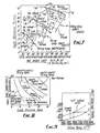
- Figure 7 shows a graph of gas turbine cycle efficiency as a function of network output, illustrating the increase of both cycle efficiency and net output with increasing firing temperature, but also showing the dropoff of cycle efficiency while net output increases as gas reheat proceeds from no reheat to full reheat.
- Figure 8 discloses another factor to be considered, namely, the amount of fuel to be burned in the reheat combustor 36 compared with the first combustor 30.
- Figure 9 illustrates the effect on output for the combined gas turbine/steam turbine cycle operating with optimum steam pressures and maximum steam temperatures and steam reheat temperature for both simple cycle and reheat cycle gas turbines, as a function of firing temperature in the first combustor 30 and reheat combustor 90. Output increases substantially as firing temperature rises, and moreover, the reheat gas turbine combined cycle output has a slightly sharper rise than the simple cycle output.
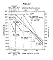
- Figure 22 also illustrates that the gas temperature to the heat recovery boiler 50 is about 1300°F (704°C) for the reheat gas turbine of my invention which is considerably above the 800 to 1000°F (427 to 538°C) state-of-the-art simple cycle industrial or aero derivative gas turbines.
- the exhaust gas in this latter case must be supplementarily fired for today's simple cycle gas turbine to obtain the desired temperature level of 1300°F (704°C).
- This procedure requires added duct burners and a greater exhaust back pressure.
- a much higher stack temperature results for the lower exhaust temperature for a given boiler approach (pinch) point.
- Power turbine exit temperatures are not as sensitive to cycle pressure ratios as gas generator exit temperatures.
- the cycle pressure ratios available range from 18 to 30, and the gas generator has a 2000°F (1093°C) or higher firing temperature, giving exit temperatures within practical limits for reheat cycle.
- the power turbine exhaust temperature is important.
- the power turbine exhaust temperature ranges are ideal for heat recovery in the combined cycle. It is well known that the best range of exit temperatures for heat recovery boilers is between 1200 and 1400°F (649 and 760°C).
- Figure 11 shows a gas generator 41A, gas generator blading 43A, a reheat combustor 30A, including fuel line 32A, fuel nozzle 34A, annular combustion region 36A, diffuser 38A, and power turbine 40A and power turbine blading 42A.
- a plurality of fuel nozzles 34A are arranged concentrically to produce the annular flow of reheat gas to drive the power turbine located rightwardly of Figure 11.
- Such gas generator and reheat combustor comprises components, such as blading 42A and 43A, which must withstand the temperatures generated by heated gases in annular gas generator combustion region 35A and power turbine combustion region 36A.
- the temperature of combustion gases obtainable is limited by the ability of internal components to maintain structural integrity and be free from corrosion for prolonged periods of operation.
- cooling of these components by use of steam permits higher operating temperatures to be attained with minimum cycle degradation and with greater efficiency than if such component were air cooled.
- An over-all increase in efficiency can result over and above the power plant efficiency approaching or exceeding 50 percent LHV. (Lower Heating Value), as disclosed above.
- an efficiency approaching or exceeding 55 percent LHV is possible with use of steam cooling and thermal barrier protection as taught by the present invention.
- the theoretical efficiency obtainable can be shown to be 56.7 percent LHV. This optimum efficiency does not compensate for blade cooling, but summarizes the theoretical maximum obtainable. If steam is used for blade cooling and if the steam can be heated to within 300°F (167°C) of the firing temperature in the process of blanket cooling or thermal barrier cooling, then the combined cycle efficiency would be slightly degraded to a value of about 56 percent LHV, and if a safety factor is applied for the steam to be heated to a lower value of approximately 600°F (333°C), then 55 percent LHV can reasonably be selected as a target efficiency vafue.
- Figure 12 illustrates typical heat flux values, where the total transfer coefficients around vane 48A are resolved into radiation and convection values, which are independent of each other.
- first-stage nozzles for gas turbines constructed according to present technology
- many cooling weep holes on the vane surface and leading edge are provided to permit cooling air to exit outwardly at a low velocity to be accelerated by the stream and carried over the vane nozzle surface.
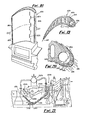
- the main gas stream must accelerate the coolant and in the process only a partial film is formed due to the mixing process that takes place and gaps between the exit holes commonly referred to as weep or gill holes. If steam is substituted for air, first-stage nozzle design of the gas generator is modified to the form shown in Figures 13, 14, 15 and 16.
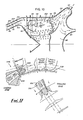
- Figure 13 suggests that leading edge 56A of vane 54A be constructed separately from vane body 58A and allowed to float as leading edge 56A expands radially inwardly from a fixed peripheral anchor point 60A. It should be noted that leading edge 56A receives the greatest heat flux from radiation and convection, and separation of leading edge 56A will keep heat away from body 58A of vane 54A. Leading edge weep-holes can additionally be employed on leading edge 56A to assist in absorption of radiant heat.
- Leading edge 56A can be made of solid ceramic material or coated with ceramic thermal heat barrier 62A and body portion 58A has extended surface horizontal fins 64A, best seen in cross-sectional view Figure 16, for convective heat removal. Fins 64A also provide steam-nozzle guides or ducts. Floating leading edge 56A can be made removable from body portion 58A so that replacement or recoating is easy during overhaul of vane 54A. Preferably, steam exits along the entire surfaces of vane 54A through leading edge nozzles 66A tangentially, or as closely as possible to tangentially, with a very small reactive velocity.
- Steam can also exit through trailing edge nozzle 67A on trailing edge portion 69A and will preferably emerge with a velocity nearly equal to the gas velocity near nozzle 67A.
- Velocity profiles of the steam and gas are shown in Figure 17 at the nozzle slot exits.
- Another advantage of steam cooling is the nozzle and blade-cleaning ability of steam when the gas turbine is shut down.
- Blade 90A shows how such a process can be accomplished using transpiration cooling with steam as the coolant. Steam is metered from plenum chamber 92A to transpiration chambers 94A through small orifices 96A. The steam under controlled pressure is then allowed to flow through porous wire braiding 98A.
- the cooling steam is introduced through the turbine wheel in a manner similar to that in which air is introduced with present conventional air cooling techniques. However, in order to obtain a higher pressure inside the blades, a modified approach is desirable, as shown in Figure 21.
- Steam enters steam header 102A of gas generator 100A.
- Gas feed line 104A furnishes combustible gas to fuel nozzle 106A, and heated gases are formed in combustion region 108A to pass through turbine wheel 110A.
- Cooling steam is introduced through turbine wheel 110A where steam lines are brought through bearing struts 112A to labyrinth packing or seal 114A at the small diameter of shafting 116A. Steam then flows internally in annular cavity 118A up to entrance holes 120A of turbine wheel 110A.
- Extraction steam is likewise used for cooling the second-stage gas generator blading.
- Steam at point 158A is extracted for cooling the first-stage blading of the power turbine where the steam is heated from point 158A to point 152A and expanded to point 154A.
- the steam previously used for the gas generator is heated in the second combustor all the way to point 148A the full reheat temperature before expansion as it is a homogeneous mixture.
- the gas turbine reheat process increases the power developed by the gas generator cooling steam.
- Heat is then recovered in the heat recovery boiler from points 150A and 154A to point 156A, the assumed 300°F (149°C) stack temperature.
- the heat in the exhaust steam is converted to useful power at an efficiency of 40.43 percent LHVto complete the cycle.
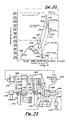
- the steam flow can be broken down for purposes of analysis schematically as shown in Figure 24.
- the cooling steam is separated from the main stream in a hypothetical way but not in reality a procedure often done in analysing single and double automatic extraction/admission steam turbine cycles.
- steam in line 160A is extracted from the high pressure steam turbine exhaust line 162A and is heated in the first stage gas generator blading-designated as heat exchanger 164A.
- the steam is now part of the gas turbine flow.
- Incremental fuel is introduced in line 163A and burned in combustor 170A to preheat this steam as it passes through and around the blading as will be shown later.
- the main fuel for the gas turbine enters through inlet line 172A.
- the cooling steam after expanding through gas generator turbine 174A, is again heated in combustor 176A at heat exchanger 178A, the heat being supplied as fuel in line 180A.
- Fuel for the main steam stream enters from line 182A; the cooling steam for the power turbine from line 184A and the main gas turbine air flow from line 186A.
- the heated gas generator turbine cooling steam then expands through power turbine 188A to produce power after which the steam is exhausted to reheat recovery boiler heat exchanger 190A, where heat is extracted to heat feed water line 192A.
- the final stack temperature of 300°F (149°C) is assumed to be compatible with the main heat-recovery boiler stack temperature.
- Cooling steam for the power turbine in line 194A is extracted from the low-pressure steam turbine 196A and is heated by power turbine first-stage blading designated as heat exchanger 198A.
- Extraction steam that flows in lines 200A, 202A and 204A is used to heat the feed water from 101°F (38.8°C) to 240°F (116°C).
- Boiler feed pump 206A raises the temperature to 250°F (121°C). It is assumed that the make-up water arrives at an enthalpy (h) of 70 to be compatible with the heat balance cycle of Figure 24.
- the total cooling steam is now heated in pseudo heat exchanger 208A by make believe fuel from line 210A to bring the steam back to the initial 2415 psia (16.55 MPa) 1000°F (538°C) condition.
- Heat exchanger 208A is used to determine the fuel required to complete the loop so that the cooling steam-cycle efficiency can be determined and evaluated.
- Table III summarizes the effect steam substitution has an over-all combined-cycle efficiency.
- cycle efficiencies are expressed in terms of fuel lower heating value abbreviated LHV, power in kilowatts (KW), and parts and proportions in percent by weight.
Landscapes
- Engineering & Computer Science (AREA)
- Chemical & Material Sciences (AREA)
- Combustion & Propulsion (AREA)
- Mechanical Engineering (AREA)
- General Engineering & Computer Science (AREA)
- Engine Equipment That Uses Special Cycles (AREA)
- Turbine Rotor Nozzle Sealing (AREA)
Claims (7)
Applications Claiming Priority (4)
| Application Number | Priority Date | Filing Date | Title |
|---|---|---|---|
| US05/954,838 US4272953A (en) | 1978-10-26 | 1978-10-26 | Reheat gas turbine combined with steam turbine |
| US954838 | 1978-10-26 | ||
| US06/047,571 US4314442A (en) | 1978-10-26 | 1979-06-11 | Steam-cooled blading with steam thermal barrier for reheat gas turbine combined with steam turbine |
| US47571 | 1979-06-11 |
Publications (3)
| Publication Number | Publication Date |
|---|---|
| EP0020594A1 EP0020594A1 (de) | 1981-01-07 |
| EP0020594A4 EP0020594A4 (de) | 1981-02-12 |
| EP0020594B1 true EP0020594B1 (de) | 1987-06-03 |
Family
ID=26725186
Family Applications (1)
| Application Number | Title | Priority Date | Filing Date |
|---|---|---|---|
| EP79901563A Expired EP0020594B1 (de) | 1978-10-26 | 1979-10-18 | Abwärme-gasturbine |
Country Status (6)
| Country | Link |
|---|---|
| US (1) | US4314442A (de) |
| EP (1) | EP0020594B1 (de) |
| JP (1) | JPS55500847A (de) |
| CA (1) | CA1160463A (de) |
| DE (1) | DE2967660D1 (de) |
| WO (1) | WO1980000864A1 (de) |
Cited By (1)
| Publication number | Priority date | Publication date | Assignee | Title |
|---|---|---|---|---|
| EP1798472A2 (de) | 2005-12-19 | 2007-06-20 | Rolls-Royce Deutschland Ltd & Co KG | Gasturbinenbrennkammer |
Families Citing this family (72)
| Publication number | Priority date | Publication date | Assignee | Title |
|---|---|---|---|---|
| US4896499A (en) * | 1978-10-26 | 1990-01-30 | Rice Ivan G | Compression intercooled gas turbine combined cycle |
| US4384823A (en) * | 1980-10-27 | 1983-05-24 | The United States Of America As Represented By The Administrator Of The National Aeronautics And Space Administration | Curved film cooling admission tube |
| DE3261410D1 (en) | 1981-04-03 | 1985-01-17 | Bbc Brown Boveri & Cie | Combined steam and gas turbine power plant |
| DE3211139C1 (de) * | 1982-03-26 | 1983-08-11 | MTU Motoren- und Turbinen-Union München GmbH, 8000 München | Axialturbinenschaufel,insbesondere Axialturbinenlaufschaufel fuer Gasturbinentriebwerke |
| US4786234A (en) * | 1982-06-21 | 1988-11-22 | Teledyne Industries, Inc. | Turbine airfoil |
| JPS59160004A (ja) * | 1983-03-01 | 1984-09-10 | Agency Of Ind Science & Technol | ガスタ−ビンの静翼 |
| US5177954A (en) * | 1984-10-10 | 1993-01-12 | Paul Marius A | Gas turbine engine with cooled turbine blades |
| US4676719A (en) * | 1985-12-23 | 1987-06-30 | United Technologies Corporation | Film coolant passages for cast hollow airfoils |
| US4669957A (en) * | 1985-12-23 | 1987-06-02 | United Technologies Corporation | Film coolant passage with swirl diffuser |
| US4705455A (en) * | 1985-12-23 | 1987-11-10 | United Technologies Corporation | Convergent-divergent film coolant passage |
| US4664597A (en) * | 1985-12-23 | 1987-05-12 | United Technologies Corporation | Coolant passages with full coverage film cooling slot |
| US4684323A (en) * | 1985-12-23 | 1987-08-04 | United Technologies Corporation | Film cooling passages with curved corners |
| US4653983A (en) * | 1985-12-23 | 1987-03-31 | United Technologies Corporation | Cross-flow film cooling passages |
| US4738588A (en) * | 1985-12-23 | 1988-04-19 | Field Robert E | Film cooling passages with step diffuser |
| US4726735A (en) * | 1985-12-23 | 1988-02-23 | United Technologies Corporation | Film cooling slot with metered flow |
| US4793716A (en) * | 1987-11-18 | 1988-12-27 | Gte Laboratories Incorporated | Thermal shock test apparatus and the method of testing |
| US4859147A (en) * | 1988-01-25 | 1989-08-22 | United Technologies Corporation | Cooled gas turbine blade |
| DE3814454A1 (de) * | 1988-04-28 | 1989-11-09 | Mtu Muenchen Gmbh | Waffensystem |
| GB2218746B (en) * | 1988-05-17 | 1992-06-17 | Rolls Royce Plc | A nozzle guide vane for a gas turbine engine |
| US4982564A (en) * | 1988-12-14 | 1991-01-08 | General Electric Company | Turbine engine with air and steam cooling |
| US5281084A (en) * | 1990-07-13 | 1994-01-25 | General Electric Company | Curved film cooling holes for gas turbine engine vanes |
| US5340274A (en) * | 1991-11-19 | 1994-08-23 | General Electric Company | Integrated steam/air cooling system for gas turbines |
| US5253976A (en) * | 1991-11-19 | 1993-10-19 | General Electric Company | Integrated steam and air cooling for combined cycle gas turbines |
| DE4223528A1 (de) * | 1992-07-17 | 1994-01-20 | Gas Elektrizitaets Und Wasserw | Verfahren zum Betreiben einer Gasturbine |
| US5320483A (en) * | 1992-12-30 | 1994-06-14 | General Electric Company | Steam and air cooling for stator stage of a turbine |
| US5406786A (en) * | 1993-07-16 | 1995-04-18 | Air Products And Chemicals, Inc. | Integrated air separation - gas turbine electrical generation process |
| US5555723A (en) * | 1994-04-28 | 1996-09-17 | Westinghouse Electric Corporation | Ducting for an external gas turbine topping combustor |
| US5839267A (en) * | 1995-03-31 | 1998-11-24 | General Electric Co. | Cycle for steam cooled gas turbines |
| US5593274A (en) * | 1995-03-31 | 1997-01-14 | General Electric Co. | Closed or open circuit cooling of turbine rotor components |
| US5536143A (en) * | 1995-03-31 | 1996-07-16 | General Electric Co. | Closed circuit steam cooled bucket |
| KR100389990B1 (ko) * | 1995-04-06 | 2003-11-17 | 가부시끼가이샤 히다치 세이사꾸쇼 | 가스터빈 |
| DE19609912A1 (de) * | 1996-03-14 | 1997-09-18 | Asea Brown Boveri | Verfahren zum Betrieb einer Kraftwerksanlage |
| DE59810230D1 (de) * | 1997-09-18 | 2003-12-24 | Siemens Ag | Turbinenschaufel sowie verwendung einer turbinenschaufel |
| US6050777A (en) * | 1997-12-17 | 2000-04-18 | United Technologies Corporation | Apparatus and method for cooling an airfoil for a gas turbine engine |
| RU2123609C1 (ru) * | 1998-05-26 | 1998-12-20 | Предприятие по добыче газа "Ямбурггаздобыча" | Способ получения тепловой и электрической энергии |
| US6099251A (en) * | 1998-07-06 | 2000-08-08 | United Technologies Corporation | Coolable airfoil for a gas turbine engine |
| US6019572A (en) * | 1998-08-06 | 2000-02-01 | Siemens Westinghouse Power Corporation | Gas turbine row #1 steam cooled vane |
| GB9821639D0 (en) * | 1998-10-06 | 1998-11-25 | Rolls Royce Plc | Coolant passages for gas turbine components |
| US6099245A (en) * | 1998-10-30 | 2000-08-08 | General Electric Company | Tandem airfoils |
| DE59808481D1 (de) * | 1998-11-09 | 2003-06-26 | Alstom Switzerland Ltd | Gekühlte Komponenten mit konischen Kühlungskanälen |
| US6241466B1 (en) * | 1999-06-01 | 2001-06-05 | General Electric Company | Turbine airfoil breakout cooling |
| US6247896B1 (en) | 1999-06-23 | 2001-06-19 | United Technologies Corporation | Method and apparatus for cooling an airfoil |
| US6280140B1 (en) | 1999-11-18 | 2001-08-28 | United Technologies Corporation | Method and apparatus for cooling an airfoil |
| RU2179096C1 (ru) * | 2000-07-26 | 2002-02-10 | Семенов Виктор Никонорович | Способ изготовления изделий сложного профиля с сетчатой оболочкой |
| RU2186223C2 (ru) * | 2000-07-26 | 2002-07-27 | Поляков Анатолий Фомич | Способ охлаждения передней кромки обтекаемого тела и устройство для его осуществления |
| US6454526B1 (en) * | 2000-09-28 | 2002-09-24 | Siemens Westinghouse Power Corporation | Cooled turbine vane with endcaps |
| RU2196907C2 (ru) * | 2001-01-31 | 2003-01-20 | Федоров Владимир Алексеевич | Электрогенерирующее устройство |
| JP3836050B2 (ja) * | 2002-06-07 | 2006-10-18 | 三菱重工業株式会社 | タービン動翼 |
| US6926496B2 (en) * | 2002-12-31 | 2005-08-09 | General Electric Company | High temperature turbine nozzle for temperature reduction by optical reflection and process for manufacturing |
| US20040258192A1 (en) * | 2003-06-16 | 2004-12-23 | General Electric Company | Mitigation of steam turbine stress corrosion cracking |
| DE10336432A1 (de) * | 2003-08-08 | 2005-03-10 | Alstom Technology Ltd Baden | Gasturbine und zugehöriges Kühlverfahren |
| EP1630356A1 (de) * | 2004-08-25 | 2006-03-01 | Siemens Aktiengesellschaft | Flüssigkeitseinspritzung in einer Gasturbine während einer Abkühlphase |
| US7316539B2 (en) * | 2005-04-07 | 2008-01-08 | Siemens Power Generation, Inc. | Vane assembly with metal trailing edge segment |
| JP4621597B2 (ja) * | 2006-01-20 | 2011-01-26 | 株式会社東芝 | 蒸気タービンサイクル |
| US7540712B1 (en) * | 2006-09-15 | 2009-06-02 | Florida Turbine Technologies, Inc. | Turbine airfoil with showerhead cooling holes |
| US9410481B2 (en) * | 2010-09-21 | 2016-08-09 | 8 Rivers Capital, Llc | System and method for high efficiency power generation using a nitrogen gas working fluid |
| US9194246B2 (en) | 2011-09-23 | 2015-11-24 | General Electric Company | Steam turbine LP casing cylindrical struts between stages |
| US9243506B2 (en) * | 2012-01-03 | 2016-01-26 | General Electric Company | Methods and systems for cooling a transition nozzle |
| DE102012209549A1 (de) * | 2012-06-06 | 2013-12-12 | Siemens Aktiengesellschaft | Kühlmittelüberbrückungsleitung für eine Gasturbine |
| US9528440B2 (en) * | 2013-05-31 | 2016-12-27 | General Electric Company | Gas turbine exhaust diffuser strut fairing having flow manifold and suction side openings |
| US10352181B2 (en) * | 2014-11-26 | 2019-07-16 | Ansaldo Energia Ip Uk Limited | Leading edge cooling channel for airfoil |
| US10443501B2 (en) * | 2015-02-05 | 2019-10-15 | Powerphase Llc | Turbocooled vane of a gas turbine engine |
| US10233779B2 (en) | 2015-02-25 | 2019-03-19 | Garrett Transportation I Inc. | Turbocharger diffuser center body |
| US10087824B2 (en) | 2015-02-25 | 2018-10-02 | Garrett Transportation 1 Inc. | Wastegate with injected flow |
| US20160326915A1 (en) * | 2015-05-08 | 2016-11-10 | General Electric Company | System and method for waste heat powered active clearance control |
| US10502066B2 (en) | 2015-05-08 | 2019-12-10 | United Technologies Corporation | Turbine engine component including an axially aligned skin core passage interrupted by a pedestal |
| US10323524B2 (en) * | 2015-05-08 | 2019-06-18 | United Technologies Corporation | Axial skin core cooling passage for a turbine engine component |
| US9752440B2 (en) | 2015-05-29 | 2017-09-05 | General Electric Company | Turbine component having surface cooling channels and method of forming same |
| US11230935B2 (en) | 2015-09-18 | 2022-01-25 | General Electric Company | Stator component cooling |
| US10436049B2 (en) * | 2016-11-17 | 2019-10-08 | United Technologies Corporation | Airfoil with dual profile leading end |
| US10753210B2 (en) * | 2018-05-02 | 2020-08-25 | Raytheon Technologies Corporation | Airfoil having improved cooling scheme |
| CN111783306B (zh) * | 2020-07-06 | 2022-11-18 | 中国航发湖南动力机械研究所 | 涡轮叶片冷气量与冷效特性分析方法 |
Citations (1)
| Publication number | Priority date | Publication date | Assignee | Title |
|---|---|---|---|---|
| US4206593A (en) * | 1977-05-23 | 1980-06-10 | Institut Francais Du Petrole | Gas turbine |
Family Cites Families (30)
| Publication number | Priority date | Publication date | Assignee | Title |
|---|---|---|---|---|
| US2675672A (en) * | 1954-04-20 | Schsrner | ||
| US1255924A (en) * | 1917-01-17 | 1918-02-12 | Willis D A Peaslee | Gas-turbine. |
| US2616252A (en) * | 1946-02-09 | 1952-11-04 | Allis Chalmers Mfg Co | Method of producing a gaseous motive fluid with pulverized fuel |
| FR1002293A (fr) * | 1946-09-03 | 1952-03-04 | Rateau Soc | Installation à turbine à gaz pour production combinée de chaleur et d'énergie et réglage de cette installation |
| US2633707A (en) * | 1946-12-16 | 1953-04-07 | Rateau Soc | Compound plant for producing mechanical power and heating steam with gas and steam turbines |
| GB656102A (en) * | 1948-08-24 | 1951-08-15 | Friedrich Kluge | Improvements relating to combined gas and steam turbine systems |
| US2743579A (en) * | 1950-11-02 | 1956-05-01 | Gen Motors Corp | Gas turbine engine with turbine nozzle cooled by combustion chamber jacket air |
| GB746377A (en) * | 1953-04-29 | 1956-03-14 | Allan Barker | Improvements in or relating to gas turbine installations |
| GB753633A (en) * | 1954-06-29 | 1956-07-25 | Westinghouse Electric Int Co | Improvements in or relating to turbines, particularly gas turbines |
| DE1074326B (de) * | 1956-10-30 | 1960-01-28 | Siemens-Schuckertwerke Aktiengesellschaft, Berlin Und Erlangen | Wärmekraftanlage |
| FR1263916A (fr) * | 1960-05-02 | 1961-06-19 | Rateau Soc | Perfectionnement aux centrales thermiques à flux combiné |
| US3240468A (en) * | 1964-12-28 | 1966-03-15 | Curtiss Wright Corp | Transpiration cooled blades for turbines, compressors, and the like |
| CH426376A (de) * | 1965-07-28 | 1966-12-15 | Bbc Brown Boveri & Cie | Verfahren zum Betrieb einer kombinierten Kraftanlage |
| US3443790A (en) * | 1966-07-08 | 1969-05-13 | Gen Electric | Steam cooled gas turbine |
| US3619077A (en) * | 1966-09-30 | 1971-11-09 | Gen Electric | High-temperature airfoil |
| US3423069A (en) * | 1967-09-29 | 1969-01-21 | Trw Inc | Airfoil |
| US3628885A (en) * | 1969-10-01 | 1971-12-21 | Gen Electric | Fluid-cooled airfoil |
| BE755567A (fr) * | 1969-12-01 | 1971-02-15 | Gen Electric | Structure d'aube fixe, pour moteur a turbines a gaz et arrangement de reglage de temperature associe |
| US3729930A (en) * | 1970-06-23 | 1973-05-01 | Rolls Royce | Gas turbine engine |
| US3816022A (en) * | 1972-09-01 | 1974-06-11 | Gen Electric | Power augmenter bucket tip construction for open-circuit liquid cooled turbines |
| US3826080A (en) * | 1973-03-15 | 1974-07-30 | Westinghouse Electric Corp | System for reducing nitrogen-oxygen compound in the exhaust of a gas turbine |
| CH558470A (de) * | 1974-01-10 | 1975-01-31 | Sulzer Ag | Kombinierte gasturbinen-dampfkraftanlage. |
| CH573044A5 (de) * | 1974-01-15 | 1976-02-27 | Sulzer Ag | |
| US4153386A (en) * | 1974-12-11 | 1979-05-08 | United Technologies Corporation | Air cooled turbine vanes |
| US4028884A (en) * | 1974-12-27 | 1977-06-14 | Westinghouse Electric Corporation | Control apparatus for controlling the operation of a gas turbine inlet guide vane assembly and heat recovery steam generator for a steam turbine employed in a combined cycle electric power generating plant |
| US4026659A (en) * | 1975-10-16 | 1977-05-31 | Avco Corporation | Cooled composite vanes for turbine nozzles |
| US4030288A (en) * | 1975-11-10 | 1977-06-21 | Caterpillar Tractor Co. | Modular gas turbine engine assembly |
| US4099374A (en) * | 1976-04-15 | 1978-07-11 | Westinghouse Electric Corp. | Gasifier-combined cycle plant |
| JPS5316109A (en) * | 1976-07-28 | 1978-02-14 | Hitachi Ltd | Cooling system of gas turbine power generating equipment |
| US4094148A (en) * | 1977-03-14 | 1978-06-13 | Stone & Webster Engineering Corporation | Thermal storage with molten salt for peaking power |
-
1979
- 1979-06-11 US US06/047,571 patent/US4314442A/en not_active Expired - Lifetime
- 1979-10-18 JP JP50197479A patent/JPS55500847A/ja active Pending
- 1979-10-18 EP EP79901563A patent/EP0020594B1/de not_active Expired
- 1979-10-18 CA CA000337963A patent/CA1160463A/en not_active Expired
- 1979-10-18 DE DE7979901563T patent/DE2967660D1/de not_active Expired
- 1979-10-18 WO PCT/US1979/000861 patent/WO1980000864A1/en not_active Ceased
Patent Citations (1)
| Publication number | Priority date | Publication date | Assignee | Title |
|---|---|---|---|---|
| US4206593A (en) * | 1977-05-23 | 1980-06-10 | Institut Francais Du Petrole | Gas turbine |
Non-Patent Citations (4)
| Title |
|---|
| BROWN BOVERI REV., vol. 65, no. 10, October 1978, pages 680-686 Baden, CH. R. KEHLHOFER: "Combined gas/steam turbine power plants for the cogeneration of heat and electricity" * |
| ENGINEERING DESIGN, COUNCIL, vol. 218, no. 4, April 1978, pages 349-351 London, G.B. H.E. JOHNSON: Industrial gas turbine developments" * |
| Münzberg HG. "FLUGANTRIEBE" 1972 Springer-Verlag Berlin, Heidelberg New York pages 308-309 * |
| WÄRME, vol. 84. no. 1, March 1978, pages 26-32 München-Graefelring, DE. J.H. THOMAS: "Entwicklungstendenzen und - probleme der thermischen Kraftwerksturbinen" * |
Cited By (2)
| Publication number | Priority date | Publication date | Assignee | Title |
|---|---|---|---|---|
| EP1798472A2 (de) | 2005-12-19 | 2007-06-20 | Rolls-Royce Deutschland Ltd & Co KG | Gasturbinenbrennkammer |
| EP1798472A3 (de) * | 2005-12-19 | 2009-01-28 | Rolls-Royce Deutschland Ltd & Co KG | Gasturbinenbrennkammer |
Also Published As
| Publication number | Publication date |
|---|---|
| CA1160463A (en) | 1984-01-17 |
| WO1980000864A1 (en) | 1980-05-01 |
| EP0020594A1 (de) | 1981-01-07 |
| US4314442A (en) | 1982-02-09 |
| EP0020594A4 (de) | 1981-02-12 |
| JPS55500847A (de) | 1980-10-23 |
| DE2967660D1 (en) | 1987-07-09 |
Similar Documents
| Publication | Publication Date | Title |
|---|---|---|
| CA1160463A (en) | Reheat gas turbine | |
| US4438625A (en) | Reheat gas turbine combined with steam turbine | |
| US4272953A (en) | Reheat gas turbine combined with steam turbine | |
| US4550562A (en) | Method of steam cooling a gas generator | |
| US4896499A (en) | Compression intercooled gas turbine combined cycle | |
| US4592204A (en) | Compression intercooled high cycle pressure ratio gas generator for combined cycles | |
| JP3068529B2 (ja) | 回転軸出力を発生する方法及び発電プラント | |
| US5775091A (en) | Hydrogen fueled power plant | |
| US5793831A (en) | Method and apparatus for improving the performance of a steam driven power system by steam mixing | |
| US5628183A (en) | Split stream boiler for combined cycle power plants | |
| US4424668A (en) | Combined gas turbine and steam turbine power station | |
| US5737912A (en) | Method for starting gas turbine in combined cycle power station | |
| JPH07301127A (ja) | ガスタービン発電プラント及びガスタービン発電プラントにおける冷却方法 | |
| US4384452A (en) | Steam-cooled blading with steam thermal barrier for reheat gas turbine combined with steam turbine | |
| US20060254280A1 (en) | Combined cycle power plant using compressor air extraction | |
| CA2324162A1 (en) | Gas turbine combined cycle system | |
| US6244033B1 (en) | Process for generating electric power | |
| US5431007A (en) | Thermochemically recuperated and steam cooled gas turbine system | |
| US4813227A (en) | Preheat gas turbine combined with steam turbine | |
| US5566542A (en) | Method for regulating and augmenting the power output of a gas turbine | |
| US20040255592A1 (en) | Method of operating a gas-turbine power plant, and gas-turbine power plant | |
| CA1170842A (en) | Steam cooled turbines | |
| JP7652462B2 (ja) | 凝縮蒸気で作動する反動タービン | |
| Rice | The combined reheat gas turbine/steam turbine cycle: part II—The LM 5000 gas generator applied to the combined reheat gas turbine/steam turbine cycle | |
| Jericha et al. | Design optimisation of the Graz cycle prototype plant |
Legal Events
| Date | Code | Title | Description |
|---|---|---|---|
| PUAI | Public reference made under article 153(3) epc to a published international application that has entered the european phase |
Free format text: ORIGINAL CODE: 0009012 |
|
| 17P | Request for examination filed |
Effective date: 19800623 |
|
| AK | Designated contracting states |
Designated state(s): CH DE FR GB SE |
|
| GRAA | (expected) grant |
Free format text: ORIGINAL CODE: 0009210 |
|
| AK | Designated contracting states |
Kind code of ref document: B1 Designated state(s): CH DE FR GB SE |
|
| REF | Corresponds to: |
Ref document number: 2967660 Country of ref document: DE Date of ref document: 19870709 |
|
| ET | Fr: translation filed | ||
| PLBE | No opposition filed within time limit |
Free format text: ORIGINAL CODE: 0009261 |
|
| STAA | Information on the status of an ep patent application or granted ep patent |
Free format text: STATUS: NO OPPOSITION FILED WITHIN TIME LIMIT |
|
| 26N | No opposition filed | ||
| PGFP | Annual fee paid to national office [announced via postgrant information from national office to epo] |
Ref country code: FR Payment date: 19911030 Year of fee payment: 13 |
|
| PGFP | Annual fee paid to national office [announced via postgrant information from national office to epo] |
Ref country code: DE Payment date: 19911104 Year of fee payment: 13 |
|
| PG25 | Lapsed in a contracting state [announced via postgrant information from national office to epo] |
Ref country code: FR Effective date: 19930630 |
|
| PG25 | Lapsed in a contracting state [announced via postgrant information from national office to epo] |
Ref country code: DE Effective date: 19930701 |
|
| REG | Reference to a national code |
Ref country code: FR Ref legal event code: ST |
|
| EAL | Se: european patent in force in sweden |
Ref document number: 79901563.1 |
|
| PGFP | Annual fee paid to national office [announced via postgrant information from national office to epo] |
Ref country code: SE Payment date: 19981014 Year of fee payment: 20 |
|
| PGFP | Annual fee paid to national office [announced via postgrant information from national office to epo] |
Ref country code: GB Payment date: 19981015 Year of fee payment: 20 Ref country code: CH Payment date: 19981015 Year of fee payment: 20 |
|
| PG25 | Lapsed in a contracting state [announced via postgrant information from national office to epo] |
Ref country code: GB Free format text: LAPSE BECAUSE OF EXPIRATION OF PROTECTION Effective date: 19991017 Ref country code: CH Free format text: LAPSE BECAUSE OF EXPIRATION OF PROTECTION Effective date: 19991017 |
|
| PG25 | Lapsed in a contracting state [announced via postgrant information from national office to epo] |
Ref country code: SE Free format text: LAPSE BECAUSE OF NON-PAYMENT OF DUE FEES Effective date: 19991019 |
|
| REG | Reference to a national code |
Ref country code: CH Ref legal event code: PUE Owner name: IVAN G. RICE TRANSFER- ABB POWER GENERATION LTD. |
|
| REG | Reference to a national code |
Ref country code: GB Ref legal event code: PE20 Effective date: 19991017 |
|
| REG | Reference to a national code |
Ref country code: CH Ref legal event code: PL |
|
| EUG | Se: european patent has lapsed |
Ref document number: 79901563.1 |
|
| REG | Reference to a national code |
Ref country code: GB Ref legal event code: 732E |