EP0020830B1 - Elément structural et panneau composite comportant un tel élément - Google Patents
Elément structural et panneau composite comportant un tel élément Download PDFInfo
- Publication number
- EP0020830B1 EP0020830B1 EP79301193A EP79301193A EP0020830B1 EP 0020830 B1 EP0020830 B1 EP 0020830B1 EP 79301193 A EP79301193 A EP 79301193A EP 79301193 A EP79301193 A EP 79301193A EP 0020830 B1 EP0020830 B1 EP 0020830B1
- Authority
- EP
- European Patent Office
- Prior art keywords
- projections
- sheet
- structural
- pattern
- structural member
- Prior art date
- Legal status (The legal status is an assumption and is not a legal conclusion. Google has not performed a legal analysis and makes no representation as to the accuracy of the status listed.)
- Expired
Links
- 239000002131 composite material Substances 0.000 title claims abstract description 31
- 239000000463 material Substances 0.000 claims abstract description 30
- 230000002093 peripheral effect Effects 0.000 claims description 10
- 230000033001 locomotion Effects 0.000 claims description 7
- 230000015572 biosynthetic process Effects 0.000 claims description 4
- 230000000903 blocking effect Effects 0.000 claims description 4
- 229910000831 Steel Inorganic materials 0.000 claims description 3
- 238000007493 shaping process Methods 0.000 claims description 3
- 239000010959 steel Substances 0.000 claims description 3
- 238000003466 welding Methods 0.000 claims description 3
- 239000012770 industrial material Substances 0.000 abstract description 5
- 238000010276 construction Methods 0.000 description 11
- 239000002184 metal Substances 0.000 description 8
- 238000009408 flooring Methods 0.000 description 5
- 238000007373 indentation Methods 0.000 description 4
- 230000003014 reinforcing effect Effects 0.000 description 4
- 238000009418 renovation Methods 0.000 description 4
- 230000008901 benefit Effects 0.000 description 3
- 238000013461 design Methods 0.000 description 3
- 238000011161 development Methods 0.000 description 3
- 230000035515 penetration Effects 0.000 description 3
- 238000012360 testing method Methods 0.000 description 3
- 239000000853 adhesive Substances 0.000 description 2
- 230000001070 adhesive effect Effects 0.000 description 2
- 238000009826 distribution Methods 0.000 description 2
- 230000004927 fusion Effects 0.000 description 2
- 238000004519 manufacturing process Methods 0.000 description 2
- NJPPVKZQTLUDBO-UHFFFAOYSA-N novaluron Chemical compound C1=C(Cl)C(OC(F)(F)C(OC(F)(F)F)F)=CC=C1NC(=O)NC(=O)C1=C(F)C=CC=C1F NJPPVKZQTLUDBO-UHFFFAOYSA-N 0.000 description 2
- 230000002787 reinforcement Effects 0.000 description 2
- 230000000712 assembly Effects 0.000 description 1
- 238000000429 assembly Methods 0.000 description 1
- 230000005540 biological transmission Effects 0.000 description 1
- 238000005266 casting Methods 0.000 description 1
- 230000000052 comparative effect Effects 0.000 description 1
- 230000006835 compression Effects 0.000 description 1
- 238000007906 compression Methods 0.000 description 1
- 230000001143 conditioned effect Effects 0.000 description 1
- 230000007812 deficiency Effects 0.000 description 1
- 230000000881 depressing effect Effects 0.000 description 1
- 239000012634 fragment Substances 0.000 description 1
- 238000009434 installation Methods 0.000 description 1
- 238000000034 method Methods 0.000 description 1
- 239000000203 mixture Substances 0.000 description 1
- 239000004033 plastic Substances 0.000 description 1
- 229920003023 plastic Polymers 0.000 description 1
- 238000003825 pressing Methods 0.000 description 1
- 230000003252 repetitive effect Effects 0.000 description 1
- 229920006395 saturated elastomer Polymers 0.000 description 1
- 238000010008 shearing Methods 0.000 description 1
- 230000003068 static effect Effects 0.000 description 1
- 238000010998 test method Methods 0.000 description 1
- 238000012546 transfer Methods 0.000 description 1
- 239000002023 wood Substances 0.000 description 1
Images



Classifications
-
- E—FIXED CONSTRUCTIONS
- E04—BUILDING
- E04C—STRUCTURAL ELEMENTS; BUILDING MATERIALS
- E04C2/00—Building elements of relatively thin form for the construction of parts of buildings, e.g. sheet materials, slabs, or panels
- E04C2/30—Building elements of relatively thin form for the construction of parts of buildings, e.g. sheet materials, slabs, or panels characterised by the shape or structure
- E04C2/32—Building elements of relatively thin form for the construction of parts of buildings, e.g. sheet materials, slabs, or panels characterised by the shape or structure formed of corrugated or otherwise indented sheet-like material; composed of such layers with or without layers of flat sheet-like material
- E04C2/326—Building elements of relatively thin form for the construction of parts of buildings, e.g. sheet materials, slabs, or panels characterised by the shape or structure formed of corrugated or otherwise indented sheet-like material; composed of such layers with or without layers of flat sheet-like material with corrugations, incisions or reliefs in more than one direction of the element
-
- E—FIXED CONSTRUCTIONS
- E04—BUILDING
- E04F—FINISHING WORK ON BUILDINGS, e.g. STAIRS, FLOORS
- E04F15/00—Flooring
- E04F15/02—Flooring or floor layers composed of a number of similar elements
- E04F15/024—Sectional false floors, e.g. computer floors
- E04F15/02405—Floor panels
- E04F15/02417—Floor panels made of box-like elements
- E04F15/02423—Floor panels made of box-like elements filled with core material
Definitions
- access flooring comprised a modular embodiment of rigid structural floor panels supported on pedestal columns and frequently requiring beam-like stringer members spanned between said columns for edge reinforcement.
- Typical assemblies were installed on top of a supporting subfloor, thus providing an adequate and secluded space to accommodate an array of power cables and the like beneath the readily accessible floor panels.
- This underfloor space or cavity also serves well as a distributions plenum for conditioned air.
- Change in location and frequent servicing of computerised equipment in an access floor environment requires repetitive physical handling of the interconnecting cables and is accomplished quite easily by the temporary removal of such modular panels. Subsequently, the underfloor cavity is exposed for complete freedom to perform any task within the maze of previously hidden wiring. When such work is finished, the modular panels fit quickly and easily back into their original position, thereby returning the area to a totally unobstructed and uniform top floor surface.
- the modular floor panels be substantially rigid, such that when loaded they do not appreciably allow flexure or retain permanent set once flexed, so that the access floor is uniformly flat and all panels are in a common plane.
- some of the earlier panels were made of substantially reinforced metal encased wood and heavy metallic castings but this has been appreciably abandoned in favour of lighter weight, high strength metal sandwich panels of which the panel comprising the subject matter of U.S. Patent No. 3 236 018, to Graham et al. dated February 22, 1966, is an example which is popular, is still being produced and is used extensively in the industry.
- An earlier example of light weight, metal constructional panels is to be found in U.S. Patent No.
- the strategic dimensional relationship is a combination of considerations of five major characteristics of the projections and their interrelation; namely (1) depth of projections for needed section modulus and moment of inertia; (2) diameter of projections to obtain their needed depth; (3) distance between the centre-lines of projections for sufficient top sheet support; (4) strategic positioning of projections to repeatedly block clear lines of vision throughout the member; and (5) remaining bottom surface material adequate to perform as a stress member and also develop necessary section modulus and moment of inertia.
- Prior art has failed to combine and/or incorporate one or more of these five structurally significant characteristics and has, therefore accomplished a less than optimum one-piece structural member which, when combined with a top sheet, does not provide an economical metal sandwich construction of desired comparable strength-to-weight ratio or structure efficiency.
- the prime object of this invention is to form, within a single sheet, a structurally efficient combination core and bottom stress member which when affixed to a planar top member surpasses the combined strength, rigidity, and economics of prior art.
- One of the principal objects of the invention is to provide a structural member comprising a one-piece rigid member formed from a sheet of structural material having formed therefrom a plurality of elongated dome-like projections extending from the plane of the said sheet, being arranged in substantially perpendicular basket weave pattern having a strategic dimensional relationship between the dimensions of said projections and the distances therebetween such that the projections repeatedly block straight lines of vision laterally in all directions across said sheet, said one piece member being capable of resistance to flexure, said elongate projections each comprising two substantially hemispherical portions connected by a saddle portion forming a generally figure 8 configuration, and portions of said member which are intermediate said elongate projections comprising continuous structural ribbon-like stress sections of fluctuating width and being arcuate in plane view and capable of optimising stress-resisting integrity of said structural member.
- said projections which form the pair which resemble a figure 8 are arranged in said sheet in a structurally strategic geometric pattern of which rows of pairs of dome-like projections are in a straight line in any direction and said rows are in a perpendicular basket weave pattern relative to each other. Said pattern repeatedly blocks straight lines of clear vision in all directions across said sheet and therefore, the occurrence of said projections in said sheet is such that the spaces between adjacent projections is inadequate to accommodate another similar projection. Said projections are spaced from each other a limited distance to provide therebetween intermediate continuous structural ribbon-like stress-sustaining sections of fluctuating width capable of optimising stress-resisting integrity with the same being arcuate in plan view and extending between the opposite edges of said sheet to sustain the stresses under load conditions.
- Such a structural member may be utilised in the manufacture of composite sections, such as access flooring, decking, or other structures which require economical high strength-to-weight ratios and structural efficiency. Additionally, they can provide structural components as in the construction of walls and other reinforcements where the individual sheet is utilised as an intermediate core member, or by itself, as a flexure-resisting component. Such one-piece structural members readily satisfy demands and applications in such marketable products as roofing, decks, wall constructions and a variety of other applications to provide structural efficiency.
- An additional object of the invention is to maintain said arcuate structural ribbon-like stress sections in their original shape under stress by the circular configuration of said projections converting load stresses, which would tend to straighten said sections, into hoop stresses around said projections, thereby resisting said tendency to straighten said sections.
- a further object of the invention is to isolate any reduction in material thickness to substantially within the formed area of the configurations themselves. This leaves optimum material in the stress-sustaining sections located where maximum section properties can be developed.
- a further object of the invention is to provide repeated blockage of clear lines of sight across said sheet in all directions. This is accomplished by several embodiments of patterns of projections, which are paired to form the elongated configuration, such as when the projections formed in a sheet of material are combined in groups of four and arranged in a rhombus pattern of a structurally strategic dimensional relationship between the diameter of said projections and the centre-to-centre distance therebetween, and adjacent rhomboidal patterns are positioned in a close perpendicular basket weave orientation.
- Said basket weave orientation in a structurally strategic geometic pattern also is produced by rows of pairs of equally-spaced in-line projections being interwoven perpendicularly with other such rows of pairs in a basket weave fashion, so that the portions of a centre line of a row of pairs of projections that lies between two aligned pairs bisects the pairs thereof in transverse rows, as shown by dotted lines in Figure 8 and also provides sufficient pattern density to block straight lines of clear vision repeatedly in all directions across said sheet to form a one-piece rigid structural member capable of resistance to flexure.
- blocking is accomplished by arranging a plurality of configurations in close proximity to each other within the pattern in which certain of said configurations resembling a figure 8 are combined with others which are circular in cross-section, at least a major portion of the circumference of all projections are circular in plan view with the combinations of said configurations and projections in said sheet being such as to repeatedly block straight lines of clear vision across said sheet.
- blockage is accomplished by including at least one drawn section formed from the original planar sheet in the same direction as said configurations, said drawn section having an area larger than said configurations surrounding said pattern. The arrangements of said configurations, projections and drawn section are designed so as to repeatedly block clear lines of vision across said sheet.
- the blocking of clear lines of sight repeatedly across said sheet provide a structural member of increased resistance to flexure due to increased structural efficiency, and when combined with a planar top sheet becomes an economical composite structural unit of substantially greater strength than one in which lines of clear vision are present around which the structural unit can be flexed.
- Still another object of the invention is to provide the location of said configurations and projections in such a manner that a composite unit which is resistant to flexure is substantially isotropic, whereby said unit when penetrated by an opening of limited cross-section located inward from the edges is resistant to flexure due to the resulting stresses in said unit when under load being redirected around said opening.
- This provides a unit which can be utilised as an access floor panel or other wall panel uses in which ready penetration can be made without significant reduction in the structural integrity of the unit in order to provide penetrations for cables, pipes, or other accesses as needed in the construction industry.
- Another further important object of the invention is to combine any of the previously described patterns of configurations and projections in a structural member with a flat sheet of structural material of similar size and shape and fixedly connect the upper ends of said projections to said flat sheet to form a composite structural panel in which said sheet of said panel is disposed uppermost in use, thereby forming load-carrying composite structures usable in many industrial applications.
- a still further object is utilisation of this composite structural member in the fabrication of access floor panels wherein the perimeter of said structural member has the outer edge portions formed at right angles to said member to provide a continuous bracing flange around the panel of a given finite size to provide a panel which can be selectively supported at the edges or corners thereof and which can accept substantial uniform or concentrated loads, such as those seen in access flooring applications.
- a still further object of the invention is to provide an integral perimeter lip bent outward from said peripheral bracing flange to provide an additional connection between said member and said top sheet which is utilised as a stiffened lip by which the access floor panel can be selectively supported at the corners or along the perimeter to develop an access floor system in combination with pedestals and/or stringers.
- a still further object of the invention is to provide said peripheral bracing flange with a greater transverse depth relative to said intermediate portion of said structural member between said projections, and in which said depth is greater than the height of said configurations and projections and a portion extending in the opposite direction from said configurations and projections and another portion extending in the same direction as said configurations and projections to provide a perimeter of increased strength and resistance to flexure, especially when utilised as an access floor panel without the use of secondary members, such as stringers or more complicated panel-to-panel hard connecting devices to prevent edge-to-edge movement.
- Another object is to form said structural member in such manner that all surfaces of said configurations and projections and the junctures thereof with said intermediate structural stress sections in the original plane of said sheet are free from sharp edges or bends whereby there are no areas or portions in said sheet which comprise corners or other shapes which normally tend to pucker or otherwise resist formation of smoothly stretched areas when formed from planar sheets and subjected to shaping by dies.
- One further object of said invention is to provide a structural member which can be combined with a similar member and fixedly connected, end-to-end, to provide a composite core structure which can be utilised in industrial application, especially where high strength-to-weight ratio properties are desired and which do not necessarily require a flat planar sheet.
- Flat planar sheets may be added to this composite structure if desired.
- the most important part of the present invention comprises a one-piece structural member formed from a sheet of industrial material which preferably comprises metal, such as steel, for example, but for certain applications of the invention, other industrial material, such as certain plastics, may be employed.
- a sheet of such industrial materials is subjected to appropriate punches and dies respectively for forming a plurality of any one of a number of different shapes, kinds, and patterns of configurations and projections, details of which are described hereinafter, said configurations and projections preferably extending from one surface of the sheet of material and all the upper ends of said configurations and projections preferably being substantially within the same plane.
- all surfaces of the major portion of the sheet are smoothly curved and are free from sharp angles or bends which otherwise would comprise corners or other shapes which normally tend to pucker or resist formation of smoothly stretched areas when formed from a planar sheet and subjected to shaping by such punches and dies.
- the formed sheet is substantially imperforate.
- FIG. 1 there is shown therein a fragmentary section of a sheet 10 of structural material, which initially is planar and the same is subjected to a set of dies to form therein a plurality of projections 12 which, as will be seen from Figures 2 and 3, are dome-shaped, are substantially hemispherical in cross-section, arranged in pairs and connected by a saddle portion 38 which as shown in cross-section in Figures 2 and 3 does not usually project as far from the original plane of sheet 10 as the pair of projections 12. From Figure 1 it will be seen that the resulting elongated configuration 40 in plan view closely resembles a figure 8, peanut-like shape.
- This arrangement provides one embodiment of configurations which adapts itself to being disposed in patterns, such as shown in one examplary manner in Figure 1, in which said configurations are in close relationship to each other, the end of one configuration 40 interfits with the adjacent configurations 40, thereby repeatedly blocking straight lines of vision laterally in all directions across sheet 10.
- said projections which form the pairs which resemble a figure 8 are arranged in said sheet in a structurally strategic geometric pattern of which rows of pairs of equally-spaced in-line projections are interwoven perpendicularly in basket weave fashion, and as further illustrated diagrammatically by broken lines in Figure 8, the portions of a centreline of a row of pairs that lies between two aligned pairs bisecting the pairs thereof in rows transverse thereto.
- Said projections are spaced a limited distance from each other so as to provide therebetween sections of the original sheet which are arcuate as indicated by the exemplary somewhat sinuous diagrammatic line 14, which outlines the intermediate continuous planar structural ribbon-like stress sections 16 of the original sheet 10.
- the projections 12 are arranged in said sheet in such manner that only a limited number, such as pairs of evenly-spaced projections, are disposed in what might be considered a straight line and, preferably, the projections are disposed in patterns in which a preferred arrangement, such as perpendicular basket weave configuration, shown diagrammatically in Figure 8, which also constitutes rhombus configurations denoted by the diagrammatic figures 18 as shown in Figure 16, which in turn, extend between the centres of the projections 12. It will also be seen that said patterns touch each other at points, whereby the illustration clearly shows the relatively saturated occurrence of the projections 12 within the sheet 10, while at the same time, permitting the occurrence of the intermediate stress sections 16 between the individual, adjacent projections 12.
- the patterns 18 of the projections 12 comprise a structurally strategic geometric pattern of a density which repeatedly blocks straight lines of clear vision in all directions across the sheet and thereby, in accordance with a major objective of the present invention, this feature provides maximum rigidity to the structural member comprising sheet 10 with the configurations 40 and projections 12 formed therein due to the inter-relationship of the diameter of the projections and the centre-to-centre distance between adjacent projections.
- the projections 12 in dome-like configuration of a thickness no greater than that of the original sheet are readily capable of being formed to a substantial height from the original plane of the sheet 10 in which, for example, the intermediate stress sections 16 are disposed as shown in an examplary manner in Figure 4 and also in Figure 5, whereby the uppermost portions of the projections 12 are thinner than the lower portions thereof, while the intermediate stress sections 16 preferably retain optimum material, thereby providing maximum stress-resisting capabilities.
- the formed structural member comprising the sheet 10 with the configurations 40 formed therein may be produced by a simple form die arrangement.
- the shape of the projections 12 also is capable of being formed without rupture or shearing and, it desired, the resulting product may be imperforate.
- the structural member when the structural member is employed in either a structural unit or finished structural panel through which, for example, cable cut-outs or the like are desired, the structural member per se may be provided with suitable openings of limited diameter in appropriate locations through both the intermediate stress sections 16 or the outer ends, for example, of the projections 12, when desired, without detracting from the stress-resisting capabilities of the structural member, due to the isotropic properties of the unit.
- the structural member comprising the sheet 10 and the configurations 40 formed therein is combined with a second planar sheet 20. Due to the fact that the upper ends of the projections 12 are substantially within a common plane, when the sheet 20 is abutted commonly with said outer ends of the projections 12, it may be secured to said upper ends by any appropriate means, such as welding, rivets, industrial adhesives, direct fusion, or any other known means of suitable nature, by which the planar sheet 20 is fixedly connected to said projections 12.
- the edges of a finite shape and size of the sheet 10 with the configurations therein are bent upwardly at a right angle to form a reinforcing bracing flange 26 which has the same vertical dimension as the height of the projections 12 and, additionally, in the embodiments shown in Figures 4-8, the terminal edge portion of the bracing flange 26, which is continuous around all four sides of the composite panel, is bent outwardly at a right angle thereto to form preferably a continuous lip 28, the upper surface of which is in a plane common with that of the upper ends of the projections 12, whereby the second planar sheet 20 commonly abuts the upper surface of the lip 28 and the upper ends of all of the projections 12, it being understood that the planar sheet 20 also will be of substantially the same finite shape and size as that of the embodiment of structural member 30 to which it is fixedly connected.
- the composite structural panel 24 shown therein is similar to the panel shown in Figures 4 and 6, except that the bracing flange 32 thereof is of a greater depth than the height of the projections 12 of the configurations 40 and is formed by means of depressing the peripheral sections 34 of the additional embodiment of structural member 36 from the remaining portions of the basic sheet 10 in a direction opposite to that from which the projections 12 extend, thereby producing a portion which extends oppositely to projections 12 and wherein said bracing flange 32 extends in the same direction as the projections 12 and is of greater vertical dimension than the flange 26 in the embodiment of Figure 4.
- the resulting composite structural panel 24, shown in Figures 5 and 7, particularly adapts this embodiment of structural panel to provide support, especially by the corners thereof.
- the intermediate stress sections 16 of the embodiments of the invention shown in the foregoing figures are arcuate and somewhat sinuous in plan view, said stress sections are maintained in said configuration and are capable of not being moved therefrom when subjected to stress due to the fact that the circular configuration of the projections 12 in cross-section converts load stress to hoop stress adjacent to the opposite sides of said stress section.
- a circular hoop is the strongest configuration for resisting deformation from its original shape when forces are supplied radially around the circumference thereof.
- the arcuate intermediate stress sections 16 extend substantially around all sides of the circular projections 12 and thereby utilise the hoop stress property of such projections advantageously for the stated purpose with respect to the stress sections 16.
- the major portion of the perimeters especially the perimeters of the opposite end portions of the configurations 40, are circular in plan view, thereby providing the aforementioned hoop stress which serves to maintain the intermediate stress sections 16.
- This is represented by the diagrammatic lines 14 in Figure 1 which illustrate the sinuous shape thereof even when the sheet 10 is subjected to loads.
- the arcuate intermediate stress sections 16 may have the effectiveness thereof increased by forming in at least certain of said sections 16 an additional embossed rib 56, several of which are illustrated in an exemplary manner in Figure 10, and also in cross-section in Figure 11, the latter figure being on a larger scale than that used in Figure 10.
- the embossed ribs 56 generally follow the shape of the arcuate, ribbon-like intermediate stress sections 16.
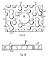
- FIG. 12 and 13 Still another embodiment of patterns of projections which may be employed in accordance with the principles of the invention is illustrated in Figures 12 and 13, in which a fragmentary section of a sheet of structural material 10 is shown, and this particular illustration embodies a mixture of different shapes of configurations and projections which are more extensively illustrated in certain of the preceding figures, and also the circular configurations 12, which similarly, are illustrated more extensively in certain of the preceding figures.
- the embodiment shown in Figures 12 and 13 also include a still further projection comprising a section 58, which is drawn from the original plane of the structural sheet 10, the drawn section 58 being of the same depth with respect to sheet 10, as the configurations 40 and the projections 12, the same being surrounded in a pattern of such projections and configurations but in a manner so that the entire pattern repeatedly blocks straight lines of clear vision between any of the sides of the structural member when viewed along a plane parallel to the intermediate stress sections 16.
- FIG. 14 and 15 Still another embodiment of the invention is illustrated in Figures 14 and 15 with regard both to structural members 30 and 34 and similar structural members 42 and 44, as well as to the composite structural panels 22 and 24 in which they respectively are included.
- This embodiment comprises terminating the bracing flanges 26 and 28 in these respective structural members and composite structural panels at the upper ends and omit the lips 28 thereon, thus butting the upper ends of the flanges directly against the adjacent surfaces of the top planar sheets 20 in said members and panels and connecting said upper ends of the flanges fixedly to the perimeters of said top planar sheets which also terminate at the vertical plane of the outside surfaces of said bracing flanges, as clearly shown in Figures 14 and 15. Under such circumstances, when the structural panels thus formed are used in an access floor, the outer surfaces of said bracing flanges of adjacent panels closely interfit in the overall access floor.
- FIGs 16 and 17 Still a further embodiment of the invention is illustrated in Figures 16 and 17, and similarly to the embodiment illustrated in Figures 10 and 11, increases the effectiveness of the arcuate intermediate stress sections 16.
- additional protrusions 60 are formed in stress sections 16 between configurations 40 and of less height than projections 12.
- projections 12 are positioned in a manner that form rhombus configurations denoted by diagrammatic figures 18.
- the additional protrusions 60 are preferably positioned in the centre of the squared areas 62 between the rhombus patterns 18 and are sized so as to retain a planar portion of each stress section 16, said portions being located between protrusions 60 and projections 12 forming the corners of the squared areas 62.
- inventions 16 and 17 can be advantageous in specialised applications requiring a small but, nevertheless increased rigidity of the embodiment of Figure 8, but could be undesirable if the application was such that an increased section depth was undesirable.
- protrusions 60 were formed in stress sections 16 and extended from the sheet in a direction opposite to the projections 12, the increased thickness of the sheet might render it undesirable in those installations requiring small clearance between sub-floor and panel.
- the present invention provides a plurality of embodiments of structural members and composite structural panels which include the same and in which such panels are relatively of light weight and embody optimisation of support by utilising the most effective strength-to-weight ratio and structural efficiency and embodying maximum resistance to deflection, as well as resistance to indentation of the planar top sheet of such panels due to the frequency of structural support therefor by projections in the structural members included therein.
- Strength-to-weight ratio in the context of the present invention, is used to related deflection under a given load to the mass weight of the material. Expressed as the following formula: the result is a numerical performance ratio, expressed as a percentage of access floor unit #1 (prior art) to access floor unit #2 (present invention).
- Data employed in the formula for the present invention is an average of 3 random samples taken from a test run, and data for panels of the prior art is derived from sample panels available on the market.
- the "structural efficiency ratio” is a comparative ratio that relates deflection, mass weight, and section depth. In essence, it is a measure of the efficiency of the panel section in its utilisation of the mass of the material. Expressed as the following formula: the result is a numerical structural efficiency ratio, expressed as a percentage of access floor unit #1 (prior art) to access floor unit #2 (present invention).
- the data employed in the formula for the present invention is an average of three sample panels taken from a test run and the data for the prior art panel is derived from sample panels available on the market.
- test method was identical for all panels tested. Three panels were selected at random from a test run of panels of the present invention and were tested along with commercially available sample panels available on the market. Each panel was placed on rigid pedestal supports without the use of edge stringers. Concentrated loads of identical magnitude were applied to the centre of the panel and at mid-span of the perimeter. Deflection readings were recorded from the bottom of the panel directly under the load. All panels were reloaded with deflection recorded again. On each loading sequence, the permanent set was also recorded.
- the following chart expresses relative "strength-to-weight” and "structural efficiency” ratios. The differences in these parameters are stated as a percentage improvement of the performance of panels of the present invention. Note that the present invention had performances superior to prior art panels and/or panels presently available on the market. As a base, the average weight of the panels of the present invention was 9.2 kg.
- the present invention demonstrates a dramatic improvement in structural efficiency and strength-to-weight ratios over all available prior art panels and panels currently being marketed.
- the present invention offers a reduction in material usage over all panels to which it was compared. It provides improved resistance to flexure when loaded and utilised as an access floor panel.
Landscapes
- Engineering & Computer Science (AREA)
- Architecture (AREA)
- Civil Engineering (AREA)
- Structural Engineering (AREA)
- General Engineering & Computer Science (AREA)
- Floor Finish (AREA)
- Panels For Use In Building Construction (AREA)
Claims (21)
Priority Applications (3)
| Application Number | Priority Date | Filing Date | Title |
|---|---|---|---|
| EP79301193A EP0020830B1 (fr) | 1979-06-20 | 1979-06-20 | Elément structural et panneau composite comportant un tel élément |
| AT79301193T ATE2452T1 (de) | 1979-06-20 | 1979-06-20 | Bauelement und ein solches bauelement aufweisende verbundplatte. |
| DE7979301193T DE2964703D1 (en) | 1979-06-20 | 1979-06-20 | Structural member and composite panel including same |
Applications Claiming Priority (1)
| Application Number | Priority Date | Filing Date | Title |
|---|---|---|---|
| EP79301193A EP0020830B1 (fr) | 1979-06-20 | 1979-06-20 | Elément structural et panneau composite comportant un tel élément |
Publications (2)
| Publication Number | Publication Date |
|---|---|
| EP0020830A1 EP0020830A1 (fr) | 1981-01-07 |
| EP0020830B1 true EP0020830B1 (fr) | 1983-02-09 |
Family
ID=8186389
Family Applications (1)
| Application Number | Title | Priority Date | Filing Date |
|---|---|---|---|
| EP79301193A Expired EP0020830B1 (fr) | 1979-06-20 | 1979-06-20 | Elément structural et panneau composite comportant un tel élément |
Country Status (3)
| Country | Link |
|---|---|
| EP (1) | EP0020830B1 (fr) |
| AT (1) | ATE2452T1 (fr) |
| DE (1) | DE2964703D1 (fr) |
Families Citing this family (7)
| Publication number | Priority date | Publication date | Assignee | Title |
|---|---|---|---|---|
| US4411121A (en) * | 1981-02-02 | 1983-10-25 | Tate Architectural Products, Inc. | Structural member with truncated conical portion and composite panel including same |
| GB2187219A (en) * | 1986-02-28 | 1987-09-03 | Mallinson Denny | Floor tile or panel with edge of base tray enfolded with edge of lid |
| US4753058A (en) * | 1986-09-11 | 1988-06-28 | Donn Incorporated | Elevated floor panel and method of manufacturing same |
| JPH0656046B2 (ja) * | 1988-08-05 | 1994-07-27 | オーエム機器株式会社 | フリーアクセス床板 |
| AU645497B2 (en) * | 1989-06-14 | 1994-01-20 | Michael Ian Johnson | High strength hollow lintel |
| WO1991005926A1 (fr) * | 1989-10-11 | 1991-05-02 | Michael Ian Johnson | Elements de construction a resistance elevee |
| CN114439590A (zh) * | 2022-01-25 | 2022-05-06 | 潍柴动力股份有限公司 | 一种耐高温排气管及其制备方法 |
Family Cites Families (2)
| Publication number | Priority date | Publication date | Assignee | Title |
|---|---|---|---|---|
| US1417664A (en) * | 1919-10-13 | 1922-05-30 | Blawknox Company | Panel |
| FR1323237A (fr) * | 1961-06-20 | 1963-04-05 | Conch Int Methane Ltd | Tôle gaufrée |
-
1979
- 1979-06-20 AT AT79301193T patent/ATE2452T1/de not_active IP Right Cessation
- 1979-06-20 EP EP79301193A patent/EP0020830B1/fr not_active Expired
- 1979-06-20 DE DE7979301193T patent/DE2964703D1/de not_active Expired
Also Published As
| Publication number | Publication date |
|---|---|
| ATE2452T1 (de) | 1983-03-15 |
| EP0020830A1 (fr) | 1981-01-07 |
| DE2964703D1 (en) | 1983-03-17 |
Similar Documents
| Publication | Publication Date | Title |
|---|---|---|
| US4203268A (en) | Structural member and composite panel including same | |
| EP0057537B1 (fr) | Elément de construction ayant une partie tronconique et panneau composite comportant de tels élements | |
| CA1151936A (fr) | Plancher sureleve a circulation d'air | |
| US4067156A (en) | Computer floor structure | |
| JP2582020Y2 (ja) | 芳香族ポリカーボネート(pc)から成る多重傾斜ウエブ板 | |
| US3011602A (en) | Panel construction | |
| US5894045A (en) | Cellular core structure building component | |
| CA1176023A (fr) | Panneau de plancher sureleve | |
| US4573304A (en) | Honeycomb floor panel and the like | |
| US4513551A (en) | Structural support | |
| US1867433A (en) | Building construction | |
| US20250314065A1 (en) | Ceiling system and method of installation | |
| GB2051909A (en) | Rigid flexure-resistant structural member and composite panel including same | |
| US12018486B2 (en) | Ceiling system and method of installation | |
| EP0020830A1 (fr) | Elément structural et panneau composite comportant un tel élément | |
| US20200362561A1 (en) | Grid Pattern Structural Shear Panels | |
| US4753058A (en) | Elevated floor panel and method of manufacturing same | |
| US4689870A (en) | Method of making honeycomb floor panel | |
| US4594833A (en) | Honeycomb floor panel and the like | |
| CA1105667A (fr) | Element de construction et panneau composite qui le renferme | |
| US7159365B2 (en) | System for making walls | |
| JPH0813685A (ja) | 剛性の高い建築用パネル | |
| DE2924864A1 (de) | Struktureller koerper und diesen aufweisende zusammengesetzte platte | |
| US20030033768A1 (en) | Access floor panel | |
| EP4656814A1 (fr) | Système et module de construction avec des fibres de bois orientées et procédé de production |
Legal Events
| Date | Code | Title | Description |
|---|---|---|---|
| PUAI | Public reference made under article 153(3) epc to a published international application that has entered the european phase |
Free format text: ORIGINAL CODE: 0009012 |
|
| AK | Designated contracting states |
Designated state(s): AT BE CH DE FR GB IT LU NL SE |
|
| 17P | Request for examination filed |
Effective date: 19810303 |
|
| ITF | It: translation for a ep patent filed | ||
| GRAA | (expected) grant |
Free format text: ORIGINAL CODE: 0009210 |
|
| AK | Designated contracting states |
Designated state(s): AT BE CH DE FR GB IT LU NL SE |
|
| REF | Corresponds to: |
Ref document number: 2452 Country of ref document: AT Date of ref document: 19830315 Kind code of ref document: T |
|
| REF | Corresponds to: |
Ref document number: 2964703 Country of ref document: DE Date of ref document: 19830317 |
|
| ET | Fr: translation filed | ||
| PG25 | Lapsed in a contracting state [announced via postgrant information from national office to epo] |
Ref country code: LU Free format text: LAPSE BECAUSE OF NON-PAYMENT OF DUE FEES Effective date: 19830630 |
|
| PLBI | Opposition filed |
Free format text: ORIGINAL CODE: 0009260 |
|
| PLBI | Opposition filed |
Free format text: ORIGINAL CODE: 0009260 |
|
| PGFP | Annual fee paid to national office [announced via postgrant information from national office to epo] |
Ref country code: LU Payment date: 19830826 Year of fee payment: 5 |
|
| 26 | Opposition filed |
Opponent name: JOHNSON MATTHEY PLC Effective date: 19830603 |
|
| 26 | Opposition filed |
Opponent name: ROPANEX PRODUCTS B.V. Effective date: 19830603 |
|
| PGFP | Annual fee paid to national office [announced via postgrant information from national office to epo] |
Ref country code: CH Payment date: 19840514 Year of fee payment: 6 |
|
| PGFP | Annual fee paid to national office [announced via postgrant information from national office to epo] |
Ref country code: FR Payment date: 19840515 Year of fee payment: 6 |
|
| PGFP | Annual fee paid to national office [announced via postgrant information from national office to epo] |
Ref country code: DE Payment date: 19840519 Year of fee payment: 6 |
|
| PGFP | Annual fee paid to national office [announced via postgrant information from national office to epo] |
Ref country code: BE Payment date: 19840630 Year of fee payment: 6 |
|
| PLBN | Opposition rejected |
Free format text: ORIGINAL CODE: 0009273 |
|
| STAA | Information on the status of an ep patent application or granted ep patent |
Free format text: STATUS: OPPOSITION REJECTED |
|
| 27O | Opposition rejected |
Effective date: 19840609 |
|
| PGFP | Annual fee paid to national office [announced via postgrant information from national office to epo] |
Ref country code: AT Payment date: 19860613 Year of fee payment: 8 |
|
| PGFP | Annual fee paid to national office [announced via postgrant information from national office to epo] |
Ref country code: NL Payment date: 19860630 Year of fee payment: 8 |
|
| PG25 | Lapsed in a contracting state [announced via postgrant information from national office to epo] |
Ref country code: AT Effective date: 19870620 |
|
| PG25 | Lapsed in a contracting state [announced via postgrant information from national office to epo] |
Ref country code: CH Effective date: 19870630 |
|
| BERE | Be: lapsed |
Owner name: TATE ARCHITECTURAL PRODUCTS INC. Effective date: 19870630 |
|
| PG25 | Lapsed in a contracting state [announced via postgrant information from national office to epo] |
Ref country code: NL Effective date: 19880101 |
|
| NLV4 | Nl: lapsed or anulled due to non-payment of the annual fee | ||
| PG25 | Lapsed in a contracting state [announced via postgrant information from national office to epo] |
Ref country code: FR Free format text: LAPSE BECAUSE OF NON-PAYMENT OF DUE FEES Effective date: 19880226 |
|
| REG | Reference to a national code |
Ref country code: CH Ref legal event code: PL |
|
| PG25 | Lapsed in a contracting state [announced via postgrant information from national office to epo] |
Ref country code: DE Effective date: 19880301 |
|
| REG | Reference to a national code |
Ref country code: FR Ref legal event code: ST |
|
| PG25 | Lapsed in a contracting state [announced via postgrant information from national office to epo] |
Ref country code: BE Effective date: 19890630 |
|
| EAL | Se: european patent in force in sweden |
Ref document number: 79301193.3 |
|
| REG | Reference to a national code |
Ref country code: GB Ref legal event code: 732E |
|
| PGFP | Annual fee paid to national office [announced via postgrant information from national office to epo] |
Ref country code: GB Payment date: 19980616 Year of fee payment: 20 |
|
| PG25 | Lapsed in a contracting state [announced via postgrant information from national office to epo] |
Ref country code: SE Free format text: LAPSE BECAUSE OF NON-PAYMENT OF DUE FEES Effective date: 19980621 |
|
| PGFP | Annual fee paid to national office [announced via postgrant information from national office to epo] |
Ref country code: SE Payment date: 19980626 Year of fee payment: 20 |
|
| PG25 | Lapsed in a contracting state [announced via postgrant information from national office to epo] |
Ref country code: GB Free format text: LAPSE BECAUSE OF NON-PAYMENT OF DUE FEES Effective date: 19990619 |
|
| REG | Reference to a national code |
Ref country code: GB Ref legal event code: PE20 Effective date: 19990619 |