EP0020865A1 - Procédé pour enlever des anneaux d'inviolabilité métalliques et dispositif pour la mise en oeuvre du procédé - Google Patents
Procédé pour enlever des anneaux d'inviolabilité métalliques et dispositif pour la mise en oeuvre du procédé Download PDFInfo
- Publication number
- EP0020865A1 EP0020865A1 EP80101411A EP80101411A EP0020865A1 EP 0020865 A1 EP0020865 A1 EP 0020865A1 EP 80101411 A EP80101411 A EP 80101411A EP 80101411 A EP80101411 A EP 80101411A EP 0020865 A1 EP0020865 A1 EP 0020865A1
- Authority
- EP
- European Patent Office
- Prior art keywords
- bottle
- locking ring
- jaws
- ring
- neck
- Prior art date
- Legal status (The legal status is an assumption and is not a legal conclusion. Google has not performed a legal analysis and makes no representation as to the accuracy of the status listed.)
- Withdrawn
Links
- 238000000034 method Methods 0.000 title claims abstract description 38
- XLYOFNOQVPJJNP-UHFFFAOYSA-N water Substances O XLYOFNOQVPJJNP-UHFFFAOYSA-N 0.000 claims abstract description 7
- 239000007788 liquid Substances 0.000 claims abstract description 6
- 239000007787 solid Substances 0.000 claims abstract description 6
- 238000009736 wetting Methods 0.000 claims abstract description 6
- 239000002184 metal Substances 0.000 claims description 4
- 239000000843 powder Substances 0.000 claims description 4
- 230000001680 brushing effect Effects 0.000 claims description 3
- 238000002844 melting Methods 0.000 abstract 1
- 230000008018 melting Effects 0.000 abstract 1
- 210000003739 neck Anatomy 0.000 description 32
- 210000001015 abdomen Anatomy 0.000 description 1
- 239000000155 melt Substances 0.000 description 1
- 229920000642 polymer Polymers 0.000 description 1
- 238000001556 precipitation Methods 0.000 description 1
Images


Classifications
-
- B—PERFORMING OPERATIONS; TRANSPORTING
- B08—CLEANING
- B08B—CLEANING IN GENERAL; PREVENTION OF FOULING IN GENERAL
- B08B9/00—Cleaning hollow articles by methods or apparatus specially adapted thereto
- B08B9/08—Cleaning containers, e.g. tanks
- B08B9/083—Removing scrap from containers, e.g. removing labels
- B08B9/0835—Removing remnants of closures from bottle necks
Definitions
- the invention relates to a method for removing the locking ring of a closure made of metal which has remained on the bottle neck of bottles after the closure has been broken open and is brushed away by means of rotating brushes; the opened locking ring further relates to an apparatus for performing the method.
- Tamper-evident locking rings of screw caps are rings that are separated from the cap when it is unscrewed and remain on the bottle neck. This circlip must then be removed when reusing the empty bottle.
- a device has become known from US Pat. No. 3,689,973 which consists of two transport screws which guide the bottle in the region of the bottle belly. Above these two transport screws, a further screw is arranged in the area of the bottle neck directly at the level of the securing ring, this screw running synchronously with the transport screws.
- the upper worm has small spikes on one edge of the worm gear, which, when the upper worm rotates, grip the locking ring, pull it up and thereby burst open.
- a brush is attached to the upper screw station, consisting of two opposing brushes, the axes of which are arranged perpendicular to the longitudinal axis of the bottle and which brush away the broken retaining ring.
- the known device is only suitable for bottles with the same diameter of the bottle neck and thus the locking ring. Only then can the spikes grasp the locking ring. In addition, with this device it is possible that, despite the correct bottle neck width, the locking ring of a bottle is not opened, because the bottle must always be in an exact positioning position so that the small mandrels can grip the locking ring. If the bottle is only tilted from the vertical away from the upper screw, the locking ring cannot be gripped by the thorns.
- the invention has for its object to provide a method and an apparatus of the type mentioned, which makes it possible to safely remove the locking ring from bottles with bottle necks of any diameter.
- the bottle neck of the bottle carrying the locking ring for opening and removing the locking ring with what ser or another liquid, solid, powder or gaseous medium is wetted then the bottle is transported between two lateral, perpendicular to the transport direction of the bottles jaws, which are then pushed together towards the bottle touch the locking ring, so that due to the electrical voltage , with which the current-carrying jaws are acted upon, a high current flows through the fuse ring and fuses, then the melted retaining ring is removed from the bottle neck by the brushes in a manner known per se, and then residual burnt-off residues of the retaining ring are brushed off the bottle neck by means of further brushes.
- the method according to the present invention has the advantage over the prior art that it can be used to remove the locking rings from any bottles with any diameter of the bottle neck and thus the locking ring.
- the bottle can be set in rotation at the latest when the burnt-off remnants of the retaining ring are brushed off.
- the bottle can be wetted with water or another liquid, solid, powdered or gaseous medium during the entire process in the area of the bottle neck.
- a device for carrying out the method according to claim 1 is characterized in that it has two opposite nozzles for applying a wetting medium to the bottle neck of a bottle, with two lateral, stressed jaws which can be displaced in the transport direction of the bottles and which melt the locking ring being attached to the nozzles connect.
- the current-conducting jaws preferably have the shape of a semicircular ring, at the ends of which inwardly projecting contact lugs are arranged.
- the device can have further brushes after the rotating brushes, which are arranged opposite one another at the level of the locking ring of the bottle and whose axes of rotation are arranged parallel to the longitudinal axis of the bottle.
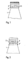
- FIG. 1 shows the closure 3 secured by means of the locking ring 2, which is located on the bottle 1. Since the locking ring 2 is connected to the closure 3, the closure 3 can only be removed from the bottle 1 by breaking the connecting webs 23.
- Figure 2 shows the locking ring 2 located on the bottle 1 after unscrewing the closure 3 according to Figure 1. It is clear that this locking ring 2 can not be removed from the bottle neck 4. In contrast, after unscrewing the closure 3 according to FIG. 1, the securing ring 2 slides downward into the position of the securing ring shown in broken lines with the reference symbol 2 '.
- the object of the present invention is to propose a method which makes it possible to completely remove the locking ring 2 from the bottle neck 4.
- FIG. 7 shows a schematic representation of the method according to the invention.
- the individual process stages are shown in FIG. 3 to FIG. 6 in section along the lines indicated in each case and are described individually below.
- Figure 3 shows the section of the schematic representation of Figure 7 along the line AB.
- Bottle 1 is located itself on a carrier plate 7.
- This carrier plate 7 can also be configured, for example, as a conveyor belt, with which it is possible to guide the bottle 1 past the respectively arranged process stages. Of course, any other way of conveying bottle 1 is also possible.
- step a shown in FIG. 3 the bottle 1 is wetted with water 6 in the area of the bottle neck 4 with the aid of two opposing nozzles 5 and 5 '.
- water any other liquid, solid, powder or gaseous medium can be used for wetting.
- This wetting serves to make the precipitations on the bottle neck 4 which arise during the subsequent burning off of the retaining rings easy to remove.
- the locking ring 2 is shown schematically to indicate that it is located in the upper region of the bottle neck 4.
- This wetting process which is shown in FIG. 3 and corresponds to process step a of the process according to the invention, can drag on to the end of process step d.
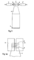
- FIG. 4a shows the section along the line CD of the schematic representation of the inventive method according to Figure 7, but with closed jaws.
- the securing ring 2 and the upper area of the bottle neck 4 are now located between the current-carrying jaws 9, which have been pushed together laterally perpendicular to the transport direction of the bottle.
- These current-carrying jaws 9 can be pushed together from the side towards the bottle and pulled apart again by known hydraulic or pneumatic, mechanical devices; They are supplied with a voltage via flexible power cables, which is sufficient to melt the circlip in a short time.
- the jaws 9 are pressed onto the locking ring during a predetermined time interval to melt the locking ring and then pulled away again.
- FIG. 4b shows a schematic top view of how the jaws 9 approach the upper part of the bottle neck 8 on both sides.
- the jaws 9 have gripped the locking ring 2 with their inwardly protruding contact / lugs 25. At this moment, a current surge flows through the circlip 2, which melts the circlip 2.
- the jaws 9 have the shape of a semicircular ring.
- FIG. 5 shows the section along the line EF of the schematic representation of the method according to the invention according to FIG. 7.
- the bottle 1 is located on the carrier plate 7, which has the same properties as those given in the description in FIG to promote bottle 1 to the four different process stages.
- 4 brushes 10 and 11 are arranged to the right and left of the bottle neck, the axes of rotation 21 and 22 (see FIG. 7) of which are arranged perpendicular to the longitudinal axis 12 of the bottle 1.
- the rotation of the brushes 10 and 11 removes the securing ring 2 which has been melted in accordance with the preceding method stage b, upwards or downwards from the bottle neck 4.
- bottles 15 and 16 are arranged to the right and left of the bottle neck, the axes of rotation 13 and 14 of which are arranged parallel to the longitudinal axis 12 of the bottle 1.
- the rotation of the brushes 15 and 16 causes the scraps of the retaining ring 2 to be brushed off the bottle neck 4.
- Bottle 1 is set in rotation at the latest in this process stage in order to optimize the brushing.
- the rotation of the bottle is advantageously opposite to the rotation of the brushes 15 and 16.
- the rotation of the bottle 1 is effected by means of the arrangement shown in FIGS. 6 and 7.
- This arrangement consists of the plate 17, past which the bottle 1 is guided.
- a plurality of rollers are located opposite the plate 17, the roller 18 being shown in dashed lines in FIG. 6 and the roller 20 being located opposite the bottle.
- nine such rollers are drawn corresponding to the rollers 18 and 20, which are located on the belt 24. If the belt 24 is now rotated by means of the system 19, the rollers slide past the bottles 1 and cause these bottles to rotate.
- FIG. 7 The process sequence of the method according to the invention is shown schematically in FIG. 7, with several successive bottles 1 being arranged one after the other and passing through the process stages one after the other.
- the direction of movement of the bottles is indicated by the arrow on the left.
- the various process stages a to d were explained above with reference to the respective corresponding FIGS. 3 to 6, which represent the section along the respective lines shown in FIG. 7.
Landscapes
- Engineering & Computer Science (AREA)
- Mechanical Engineering (AREA)
- Sealing Of Jars (AREA)
Applications Claiming Priority (2)
| Application Number | Priority Date | Filing Date | Title |
|---|---|---|---|
| DE2917785 | 1979-05-03 | ||
| DE19792917785 DE2917785C2 (de) | 1979-05-03 | 1979-05-03 | Vorrichtung zum Entfernen des Sicherungsringes eines Verschlusses aus Metall von einem Flaschenhals |
Publications (1)
| Publication Number | Publication Date |
|---|---|
| EP0020865A1 true EP0020865A1 (fr) | 1981-01-07 |
Family
ID=6069805
Family Applications (1)
| Application Number | Title | Priority Date | Filing Date |
|---|---|---|---|
| EP80101411A Withdrawn EP0020865A1 (fr) | 1979-05-03 | 1980-03-18 | Procédé pour enlever des anneaux d'inviolabilité métalliques et dispositif pour la mise en oeuvre du procédé |
Country Status (2)
| Country | Link |
|---|---|
| EP (1) | EP0020865A1 (fr) |
| DE (1) | DE2917785C2 (fr) |
Citations (5)
| Publication number | Priority date | Publication date | Assignee | Title |
|---|---|---|---|---|
| FR800901A (fr) * | 1935-04-24 | 1936-07-22 | Procédé et appareil pour le nettoyage extérieur des bouteilles et autres récipients | |
| US2716687A (en) * | 1953-01-29 | 1955-08-30 | Loftus Engineering Corp | Apparatus for treating metal sheets |
| FR1470331A (fr) * | 1965-12-14 | 1967-02-24 | Rene Combastet & Cie | Procédé et dispositif pour enlever automatiquement les capsules, collerettes de surbouchage et autres subsistants sur des bouteilles ou analogues devant être nettoyées |
| US3909575A (en) * | 1974-01-31 | 1975-09-30 | S G Taylor Chain Company Inc | Chain link heat treating apparatus and method |
| DE2729980B1 (de) * | 1977-07-02 | 1978-11-09 | Alcoa Deutschland Gmbh Maschb | Verfahren zur Entfernung des Sicherungsringes eines Verschlusses aus Metall oder Kunststoff von Flaschen und Vorrichtung zur Durchfuehrung des Verfahrens |
Family Cites Families (1)
| Publication number | Priority date | Publication date | Assignee | Title |
|---|---|---|---|---|
| US3689973A (en) * | 1970-10-08 | 1972-09-12 | Joseph Jacques Leenaards | Apparatus for the removal of unbroken or insufficiently broken pilferproof rings of screw-caps from the neck of bottles |
-
1979
- 1979-05-03 DE DE19792917785 patent/DE2917785C2/de not_active Expired
-
1980
- 1980-03-18 EP EP80101411A patent/EP0020865A1/fr not_active Withdrawn
Patent Citations (5)
| Publication number | Priority date | Publication date | Assignee | Title |
|---|---|---|---|---|
| FR800901A (fr) * | 1935-04-24 | 1936-07-22 | Procédé et appareil pour le nettoyage extérieur des bouteilles et autres récipients | |
| US2716687A (en) * | 1953-01-29 | 1955-08-30 | Loftus Engineering Corp | Apparatus for treating metal sheets |
| FR1470331A (fr) * | 1965-12-14 | 1967-02-24 | Rene Combastet & Cie | Procédé et dispositif pour enlever automatiquement les capsules, collerettes de surbouchage et autres subsistants sur des bouteilles ou analogues devant être nettoyées |
| US3909575A (en) * | 1974-01-31 | 1975-09-30 | S G Taylor Chain Company Inc | Chain link heat treating apparatus and method |
| DE2729980B1 (de) * | 1977-07-02 | 1978-11-09 | Alcoa Deutschland Gmbh Maschb | Verfahren zur Entfernung des Sicherungsringes eines Verschlusses aus Metall oder Kunststoff von Flaschen und Vorrichtung zur Durchfuehrung des Verfahrens |
Also Published As
| Publication number | Publication date |
|---|---|
| DE2917785C2 (de) | 1982-12-09 |
| DE2917785A1 (de) | 1980-11-13 |
Similar Documents
| Publication | Publication Date | Title |
|---|---|---|
| DE2757890A1 (de) | Verfahren und vorrichtung zum herstellen von behaeltnissen aus roehrenglas, insbesondere ampullen | |
| DE102006033512B4 (de) | Behandlungsmaschine für Flaschen oder dergleichen Behälter | |
| DE3539890A1 (de) | Maschine zum trocknen der aeusseren oberflaeche von gefuellten weinflaschen | |
| DE2729980C2 (de) | Verfahren zur Entfernung des Sicherungsringes eines Verschlusses aus Metall oder Kunststoff von Flaschen und Vorrichtung zur Durchführung des Verfahrens | |
| DE2726337C2 (de) | Flaschenträger | |
| DE7231517U (de) | Vorrichtung zum herstellen eines hohlen metallgegenstandes mit sphaerisch ausgebildeter schale | |
| EP0020865A1 (fr) | Procédé pour enlever des anneaux d'inviolabilité métalliques et dispositif pour la mise en oeuvre du procédé | |
| DE2830148A1 (de) | Flaschenzufuehr- und -ausrichteinrichtung | |
| DE4326813C2 (de) | Verfahren und Geräte zum Entfernen von Behälter-Verschlüssen | |
| DE4114889A1 (de) | Verfahren und vorrichtung zum befuellen und verschliessen von gefaessen | |
| DE3626008A1 (de) | Vorrichtung zum verschliessen von flaschen | |
| DE7836568U1 (de) | Vorrichtung zur kontinuierlichen behandlung von dem umfang eines karussells o.dgl. zugefuehrten gegenstaenden, insbesondere flaschen | |
| DE2407173A1 (de) | Ausrichtrollenbahn | |
| DE102023111939A1 (de) | Behälterbehandlungsanlage sowie Verfahren zum Betreiben einer Behälterbehandlungsanlage | |
| DE2709101A1 (de) | Kontakthalter fuer graphitelektroden | |
| DE3402911A1 (de) | Vorrichtung zum halten von hohlkoerpern | |
| DE3331217A1 (de) | Vorrichtung zum automatischen abbuersten von flaschenkapseln | |
| DE3015595A1 (de) | Vorrichtung zum etikettieren von flaschen | |
| DE2558686C3 (de) | Vorrichtung zum Auflösen von Stückgutlagen in Stückgutzeilen | |
| DE2322219A1 (de) | Verfahren und vorrichtung zur entfernung von etiketten und schraubverschluessen von behaeltern, wie flaschen o.dgl | |
| DE388075C (de) | Vorrichtung zum elektrischen Verloeten der Laengskanten von Konservenbuechsen u. dgl. | |
| DE9306597U1 (de) | Vorrichtung für die Abgabe von Produkten an eine Aufnahmestation | |
| DE2044882A1 (de) | Positioniereinrichtung fur korn sehe Gegenstande | |
| DE3213755A1 (de) | Vorrichtung zum entfernen von fadenunterwindungen | |
| DE2954168C2 (de) | Vorrichtung zur Überführung einer Verschlußkappe |
Legal Events
| Date | Code | Title | Description |
|---|---|---|---|
| PUAI | Public reference made under article 153(3) epc to a published international application that has entered the european phase |
Free format text: ORIGINAL CODE: 0009012 |
|
| AK | Designated contracting states |
Designated state(s): AT BE CH FR GB IT LU NL SE |
|
| 17P | Request for examination filed |
Effective date: 19801112 |
|
| STAA | Information on the status of an ep patent application or granted ep patent |
Free format text: STATUS: THE APPLICATION HAS BEEN WITHDRAWN |
|
| 18W | Application withdrawn |
Withdrawal date: 19820107 |
|
| RIN1 | Information on inventor provided before grant (corrected) |
Inventor name: KIEFER, ERNST, ING.-GRAD. Inventor name: INDIHAR, MAXIMILIAN |