EP0020880A1 - Dispositif optique pour la détection des défauts de bandes de matériaux - Google Patents
Dispositif optique pour la détection des défauts de bandes de matériaux Download PDFInfo
- Publication number
- EP0020880A1 EP0020880A1 EP80101712A EP80101712A EP0020880A1 EP 0020880 A1 EP0020880 A1 EP 0020880A1 EP 80101712 A EP80101712 A EP 80101712A EP 80101712 A EP80101712 A EP 80101712A EP 0020880 A1 EP0020880 A1 EP 0020880A1
- Authority
- EP
- European Patent Office
- Prior art keywords
- mirror
- light
- optical
- scanning
- accordance
- Prior art date
- Legal status (The legal status is an assumption and is not a legal conclusion. Google has not performed a legal analysis and makes no representation as to the accuracy of the status listed.)
- Granted
Links
- 230000003287 optical effect Effects 0.000 title claims abstract description 38
- 239000000463 material Substances 0.000 title claims abstract description 21
- 239000011324 bead Substances 0.000 claims abstract description 21
- 230000002093 peripheral effect Effects 0.000 claims description 4
- 238000001514 detection method Methods 0.000 description 5
- 239000002759 woven fabric Substances 0.000 description 3
- 230000005540 biological transmission Effects 0.000 description 2
- 230000015572 biosynthetic process Effects 0.000 description 2
- 238000006073 displacement reaction Methods 0.000 description 2
- 230000000694 effects Effects 0.000 description 2
- 239000004411 aluminium Substances 0.000 description 1
- 229910052782 aluminium Inorganic materials 0.000 description 1
- XAGFODPZIPBFFR-UHFFFAOYSA-N aluminium Chemical compound [Al] XAGFODPZIPBFFR-UHFFFAOYSA-N 0.000 description 1
- 238000010276 construction Methods 0.000 description 1
- 230000007547 defect Effects 0.000 description 1
- 230000004069 differentiation Effects 0.000 description 1
- 230000002349 favourable effect Effects 0.000 description 1
- 238000003384 imaging method Methods 0.000 description 1
- 230000010354 integration Effects 0.000 description 1
- 229910052751 metal Inorganic materials 0.000 description 1
- 239000002184 metal Substances 0.000 description 1
- 238000012544 monitoring process Methods 0.000 description 1
- 239000004753 textile Substances 0.000 description 1
Images

Classifications
-
- D—TEXTILES; PAPER
- D06—TREATMENT OF TEXTILES OR THE LIKE; LAUNDERING; FLEXIBLE MATERIALS NOT OTHERWISE PROVIDED FOR
- D06H—MARKING, INSPECTING, SEAMING OR SEVERING TEXTILE MATERIALS
- D06H3/00—Inspecting textile materials
- D06H3/08—Inspecting textile materials by photo-electric or television means
-
- G—PHYSICS
- G01—MEASURING; TESTING
- G01N—INVESTIGATING OR ANALYSING MATERIALS BY DETERMINING THEIR CHEMICAL OR PHYSICAL PROPERTIES
- G01N21/00—Investigating or analysing materials by the use of optical means, i.e. using sub-millimetre waves, infrared, visible or ultraviolet light
- G01N21/84—Systems specially adapted for particular applications
- G01N21/88—Investigating the presence of flaws or contamination
- G01N21/89—Investigating the presence of flaws or contamination in moving material, e.g. running paper or textiles
- G01N21/8901—Optical details; Scanning details
Definitions
- the invention relates to optical fault seeking apparatus for material webs and has particular reference to fault seeking apparatus of the kind in which an optical scanning device including mirror wheel means and a laser is used to generate a scanning light beam and to project the scanning light beam onto the web.
- the scanning light beam cyclically scans the material web,which is arranged to move past the scanning device, transversely to its length and one or more light receiving devices pick up light reflected from the web and/or passing through the web.
- The,or each,light receiving device includes at least one photoelectric converter which produces an electrical signal corresponding to the light received. The presence ofabsence of;or variations in the signals provide information as to the presence and nature of a fault in the material web.
- Optical fault seeking apparatus of this kind consists essentially of a laser light source, an objective and a mirror wheel arranged at the focal point of a strip-like concave mirror.
- the mirror wheel periodically scans the light beam received from the objective over the concave mirror from which there emerges the scanning light beam which is continuously displaced parallel to itself and which is directed to the scanning plane in which the material web is moved in its longitudinal direction.
- the scanning of the material web takes place point by point line by line and transverse to the longitudinal extent or direction of movement of the material web.
- a light receiving device can be arranged in front of or behind the material web depending on whether the fault seeking apparatus operates in reflection (remission) or transmission. It is also possible to use two or more light receiving devices and to monitor both light reflected byand light transmitted through the web.
- the light receiving device generally consists of a cylindrical lens arranged parallel to the path of the scanning light bead generated by the scanning light beam on the web and a light conducting rod arranged behind the cylindrical lens with a photomultiplier at one of the end faces of the light conducting rod.
- a further optical system is generally located between the laser and the objective of the light transmitting device in order to focus the parallel laser beam.
- the scanning device invariably includes a slot aperture and the objective generally produces an image of this slot in the scanning plane on the surface of the material web.
- Structured material such as woven fabrics are generally investigated,in the first instance,in transmission.
- the surface structure of sheet metal for example sheet aluminium for use in offset printingis preferably monitored in remission.
- the principle object underlying the present invention is now to provide optical fault seeking apparatus for material webs of the kind previously named,the response of which can be optimized for the simultaneous detection of very different types of faults.
- the invention envisages, in apparatus of the above named kind, that the mirror wheel means has at least first and second alternately operating types of mirror surfaces of which the first projects a first light bead having a first characteristic onto the scanning plane and the second projects a second light bead having a second, different characteristic onto the scanning plane.
- the first and second characteristics would generally be the size, or the shape,or the size and shape of the first and second light beads.
- the thought underlying the invention can thus be seen to be the use of a special mirror wheel which alternately projects, in rapid succession one after the other, into the scanning plane, two different scanning light beads which are respectively optimized with respect to their shape and size for the detection of different types of faults.
- This idea can also be extended by providing the mirror wheel with more than two different types of mirror surfaces in order to achieve a better differentiation during fault recognition.
- the optical scanning device includes an anamorphotic lens system by means of which two slot images extending parallel.to the scanning plane and at right angles to one another can be generated and in which the mirror wheel means has two kinds of mirror surfaces which are preferably alternately operative, and of which the one projects one of the slot images into the scanning plane and the other projects the other slot image at right angles to the first slot image into the scanning plane.
- the apparatus is thus optimized for the detection of the faults which prevail in woven fabrics in particular for the recognition of warp and weft thread breakages by arranging for the scanning light bead to be a rapid succession of images of slots alternately extending in, and transverse to,the transport direction of the web.
- the light receiving device responds in optimized fashion to the transversely disposed slot image, however, for weft thread breakages it is primarily the slot image which extends at right angles to the scanning direction which produces the optimium response of the light receiving device.
- One practical embodiment is characterized in that the two slot images are spaced apart in the direction at right angles to the scanning plane and that the mirror wheel has mirror surfaces of different optical power, which are preferably alternately arranged around the periphery of the mirror wheel.
- the mirror wheel can usefully have plane and curved mirror surfaces in which the curved mirror surfaces are usefully of concave curvature.
- the curved mirror surfaces can be either of cylindrical or spherical curvature.
- a further embodiment features an arrangement in which the mirror wheel means comprises two mirror wheels arranged one adjacent the other with the mirror wheels being displaced by a fraction of a pitch relative to one another in the peripheral direction.
- the mirror wheel means comprises two mirror wheels arranged one adjacent the other with the mirror wheels being displaced by a fraction of a pitch relative to one another in the peripheral direction.
- the two mirror wheels can either have mirror surfaces of different refractive power, by arranging for example for one mirror wheel to have only flat mirror surfaces and the other to have only preferably concave, spherical or cylindrical mirror surfaces, or both mirror wheels can have only plane mirror surfaces and the optical means which cooperate with the two mirror wheels can generate differently shaped and/or dimensioned light beads, in particular two slot images which are at right angles to one another.
- the optical means which cooperate with the two mirror wheels can be responsible for ensuring the appearance in the scanning plane of, on the one hand a slot image extending in the scanning direction and, on the other hand, a slot image extending at right angles to the scanning direction.
- a laser 17 transmits a parallel light beam 18 to an anamorphotic lens system 11 which consists of a micro-objective 19 and a cylindrical lens 20 arranged behind the micro-objective 19 with the axis of the cylindrical lens extending substantially parallel to the rotational axis of a mirror wheel 14.
- the light beam emerging from the anamorphotic system 11 reaches a strip-like concave mirror 23 via an objective 22 and the mirror surfaces 15, 16 of a mirror wheel 14.
- the strip-like concave mirror 23 focusses the light beam into the vicinity of the scanning plane 12.
- the axis .21 of the mirror wheel 14 is somewhat tilted relative to the normal to the optical axis of the objective 22 in order to be able to arrange the strip-like concave mirror 23 alongside the light beam which emerges from the objective 22 and to lead the scanning beam 24,which emerges from the concave mirror 23,past the mirror wheel 14.
- the anamorphotic system 11 together with the objective 22 and the strip-like concave mirror 23 in the plane of Fig. 1 sharply images a gap-like light bead 13 in the scanning plane 12.
- the scanning direction in Fig. 1 is at right angles to the plane of the drawing.
- the material web arranged in the scanning plane 12 moves in the direction of the arrow f.
- the plane mirror surfaces 15 and the concavely curved mirror surfaces 16 alternate around the periphery of the mirror wheel 14.
- the mirror wheel 14 is constructed as a tandem mirror wheel with two coaxial mirror wheels 14', 14" which contact one another and which are mutually displaced in the peripheral direction by one half of a mirror surface division, i. e. by one half pitch.
- the mirror surfaces 15, 16 of the two mirror wheelsl4', 14" are plane in the presently described embodiment.
- the objective 22 is,however, divided in accordance with the invention into two halves 22', 22" so that each of the halves 22', 22" of the objective illuminates one of the mirror wheels 14', 14" respectively.
- the two objective halves 22', 22" are displaced from one another in the direction of the optical axis 25 by a distance which is sufficient that the so-called intersect difference "a" is balanced out.
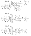
- the slot image 13,and the slot.image 13' which extends at right angles thereto, are imaged, in the scanning plane 12 by the mirror wheel 14' and the other mirror wheel 1411 respectively.
- the two partial objectives 22', 22'' naturally also image the. slot images in front of or behind the scanning plane 12 as is indicated in Figs. 5 to 7.
- Fig. 6 illustrates the image formation by the mirror wheel 14' and the objective half 22' of the slot image 13' which is directed in the transport direction f.
- Fig. 7 shows the image formation by the mirror wheel 14" and the objective half 22' of the slot image 13 which extends at right angles to the transport direction f.
- the arrangement can also be such that one of the two mirror wheels has only plane surfaces whilst the other is constructed only with spherical or cylindrical mirror surfaces.
- the advantage of this arrangement would be a higher scanning frequency.
- the mirror wheel means of the invention also means that sharp points and sharp slots can be alternately projected onto the material web.
- the combination of a sharp image/unsharp image, i. e. for example a smaller point/larger point or a narrower/wider slot image, can also be realized.
- An important feature of the subject of the invention is the fact that the differential characteristics of the light beads in the scanning plane are achieved only with a single light source which is preferably constructed as a laser.
- each objective half has a different focal length such that for the one focal length the one slot image 13, and for the other focal length the other slot image 13' is sharply imaged in the scanning plane 12.
- each second mirror wheel surface is provided with additional optical power which is achieved in one embodiment by providing every second mirror wheel surface with a spherical profile.
- Cylindrical surfaces can also be basically used, one then no longer achieves a rotated image but rather the slot image formed via the flat surface is contracted to a point by the effects of the cylindrical curvature.
- the differential focussing can be achieved by axial displacement or differential focal length of the two parts of the objective.
Landscapes
- Engineering & Computer Science (AREA)
- Textile Engineering (AREA)
- Chemical & Material Sciences (AREA)
- Biochemistry (AREA)
- Physics & Mathematics (AREA)
- Health & Medical Sciences (AREA)
- Life Sciences & Earth Sciences (AREA)
- Analytical Chemistry (AREA)
- Materials Engineering (AREA)
- General Health & Medical Sciences (AREA)
- General Physics & Mathematics (AREA)
- Immunology (AREA)
- Pathology (AREA)
- Investigating Materials By The Use Of Optical Means Adapted For Particular Applications (AREA)
- Lenses (AREA)
- Treatment Of Fiber Materials (AREA)
Applications Claiming Priority (2)
| Application Number | Priority Date | Filing Date | Title |
|---|---|---|---|
| DE2925734 | 1979-06-26 | ||
| DE2925734A DE2925734C3 (de) | 1979-06-26 | 1979-06-26 | Optisches Fehlersuchgerät für Materialbahnen |
Publications (2)
| Publication Number | Publication Date |
|---|---|
| EP0020880A1 true EP0020880A1 (fr) | 1981-01-07 |
| EP0020880B1 EP0020880B1 (fr) | 1984-07-11 |
Family
ID=6074189
Family Applications (1)
| Application Number | Title | Priority Date | Filing Date |
|---|---|---|---|
| EP80101712A Expired EP0020880B1 (fr) | 1979-06-26 | 1980-03-31 | Dispositif optique pour la détection des défauts de bandes de matériaux |
Country Status (4)
| Country | Link |
|---|---|
| US (1) | US4357071A (fr) |
| EP (1) | EP0020880B1 (fr) |
| JP (1) | JPS567042A (fr) |
| DE (1) | DE2925734C3 (fr) |
Cited By (4)
| Publication number | Priority date | Publication date | Assignee | Title |
|---|---|---|---|---|
| EP0088243A3 (fr) * | 1982-03-05 | 1984-11-07 | Feldmühle Aktiengesellschaft | Procédé pour contrôler des matériaux se mouvant dans une direction |
| EP0088230A3 (fr) * | 1982-03-05 | 1984-11-28 | Feldmühle Aktiengesellschaft | Procédé pour contrôler des objets en matériau ferromagnétique |
| EP0274572A3 (en) * | 1987-01-12 | 1990-01-31 | Erwin Sick Gmbh Optik-Elektronik | Device for the optical scanning of objects, especially record discs |
| EP0757245A3 (fr) * | 1995-08-03 | 1997-06-25 | Tzn Forschung & Entwicklung | Dispositif pour détecter des défauts de surfaces en forme de bandes longitudinales |
Families Citing this family (21)
| Publication number | Priority date | Publication date | Assignee | Title |
|---|---|---|---|---|
| DE3125189C2 (de) * | 1981-06-26 | 1984-06-14 | Erwin Sick Gmbh Optik-Elektronik, 7808 Waldkirch | Fehlersuchgerät für breite Bahnen |
| US4538895A (en) * | 1983-03-07 | 1985-09-03 | International Business Machines Corporation | Scanning optical system for use with a semiconductor laser generator |
| US4560862A (en) * | 1983-04-26 | 1985-12-24 | Skan-A-Matic Corp. | System for optical scanning over a large depth of field |
| DE3446354A1 (de) * | 1984-12-19 | 1986-06-26 | Erwin Sick Gmbh Optik-Elektronik, 7808 Waldkirch | Optoelektronische vergleichsvorrichtung fuer strukturen auf ebenen oberflaechen oder fuer flaechige strukturen |
| DE3534019A1 (de) * | 1985-09-24 | 1987-04-02 | Sick Optik Elektronik Erwin | Optische bahnueberwachungsvorrichtung |
| DE3709500A1 (de) * | 1985-09-24 | 1988-10-06 | Sick Optik Elektronik Erwin | Optische bahnueberwachungseinrichtung mit zeilenkameras mit gerichteter beleuchtung |
| US5033845A (en) * | 1985-10-15 | 1991-07-23 | Canon Kabushiki Kaisha | Multi-direction distance measuring method and apparatus |
| DE3602008A1 (de) * | 1986-01-23 | 1987-07-30 | Sick Optik Elektronik Erwin | Optische abtastvorrichtung mit einem spiegelrad |
| US4748316A (en) * | 1986-06-13 | 1988-05-31 | International Business Machines Corporation | Optical scanner for reading bar codes detected within a large depth of field |
| GB2202627A (en) * | 1987-03-23 | 1988-09-28 | Sick Optik Elektronik Erwin | Optical arrangement in web monitoring device |
| JP2502314B2 (ja) * | 1987-07-06 | 1996-05-29 | 株式会社テック | ポストオブジェクティブ型光偏向器 |
| DE3729804A1 (de) * | 1987-09-05 | 1989-03-16 | Menschner Maschf Johannes | Verfahren zur automatischen erkennung von fehlern in bewegten warenbahnen |
| DE3806385A1 (de) * | 1988-02-29 | 1989-09-07 | Feldmuehle Ag | Verfahren und vorrichtung zum pruefen von transparenten bahnen |
| DE3819183A1 (de) * | 1988-06-06 | 1989-12-07 | Sick Optik Elektronik Erwin | Verfahren zur fehlererkennung bei laufenden materialbahnen |
| US4978185A (en) * | 1989-10-25 | 1990-12-18 | Xerox Corporation | Raster scanning system utilizing overfilled polygon facet design with non-reflective facet edges |
| JPH03177810A (ja) * | 1989-12-07 | 1991-08-01 | Toshiba Corp | 光偏向装置 |
| JP3198103B2 (ja) * | 1989-12-07 | 2001-08-13 | 株式会社東芝 | 光偏向装置の製造方法 |
| US5073702A (en) * | 1990-03-26 | 1991-12-17 | Ncr Corporation | Multiple beam bar code scanner |
| JP3126137B2 (ja) * | 1990-11-01 | 2001-01-22 | 松下電器産業株式会社 | ポストオブジェクティブ型走査光学系及び画像形成装置 |
| DE102017127420A1 (de) * | 2017-11-21 | 2019-05-23 | Sick Ag | Polygonscanner und Verfahren zum Erfassen von Objekten in einem Überwachungsbereich |
| CN109932826B (zh) * | 2019-04-29 | 2023-10-31 | 中国工程物理研究院激光聚变研究中心 | 一种用于光学元件缺陷检测的拼接式条形激光装置 |
Citations (17)
| Publication number | Priority date | Publication date | Assignee | Title |
|---|---|---|---|---|
| US2617048A (en) * | 1948-01-09 | 1952-11-04 | Ibm | Photoelectric inspection device |
| GB754026A (en) * | 1954-05-26 | 1956-08-01 | Nat Lab And Mfg Corp | Means for observing superposed impressions on a moving web |
| US3474254A (en) * | 1968-02-26 | 1969-10-21 | Sick Erwin | Photoelectronic apparatus for scanning textile material |
| US3803474A (en) * | 1971-11-30 | 1974-04-09 | Ferranti Ltd | Detection of blemishes on surfaces |
| US3814945A (en) * | 1971-03-09 | 1974-06-04 | Sira Institute | Apparatus for automatic inspection of materials |
| DE2436110A1 (de) * | 1973-07-27 | 1975-02-06 | Du Pont | Wandernder-lichtfleck-ueberwachungssysteme fuer zusammenhaengende materialbahnen |
| US3866054A (en) * | 1973-09-28 | 1975-02-11 | Du Pont | Defect size discriminator circuit for web inspection system |
| DE2446114A1 (de) * | 1973-09-28 | 1975-04-10 | Kawasaki Steel Co | System zur bestimmung der querlage von schadstellen an ablaufenden baendern |
| DE2449584A1 (de) * | 1973-10-24 | 1975-04-30 | Strauss Levi & Co | Verfahren und anordnung zur feststellung von fehlern in textilstoffen |
| DE1460567B2 (de) * | 1964-06-08 | 1975-06-26 | Henri Genf Eicken (Schweiz) | Vorrichtung zum Feststellen von Fehlern in der Oberflächenstruktur bewegter Textilbahnen |
| DE2363422A1 (de) * | 1973-12-20 | 1975-06-26 | Agfa Gevaert Ag | Verfahren und vorrichtung zur ermittlung von laengsfehlern auf bewegten materialbahnen |
| GB1399298A (en) * | 1972-09-14 | 1975-07-02 | Sick Optik Elektronik Erwin | Photoelectric surface scanning device |
| US3906232A (en) * | 1973-10-31 | 1975-09-16 | Butler Automatic Inc | Web break detector |
| DE2613921A1 (de) * | 1975-03-31 | 1976-10-21 | Asahi Chemical Ind | Vliesstoffehler-feststelleinrichtung |
| US4013367A (en) * | 1974-05-13 | 1977-03-22 | Tokyo Shibaura Electric Co., Ltd. | Apparatus for detecting irregularities in the surfaces of materials |
| FR2331788A1 (fr) * | 1975-11-12 | 1977-06-10 | Sick Optik Elektronik Erwin | Dispositif de balayage pour feuilles ou bandes continues de materiau pour la determination de defauts ou deteriorations |
| DE2707538A1 (de) * | 1976-02-23 | 1977-09-01 | Greenwood Mills Inc | Verfahren zur automatischen fehlerpruefung textiler flaechengebilde |
Family Cites Families (6)
| Publication number | Priority date | Publication date | Assignee | Title |
|---|---|---|---|---|
| US3488102A (en) * | 1966-03-25 | 1970-01-06 | Technical Operations Inc | Laser beam scanning apparatus |
| GB1462875A (en) * | 1973-05-16 | 1977-01-26 | Ciba Geigy Ag | Method of scanning a surface |
| US4057351A (en) * | 1976-02-23 | 1977-11-08 | Greenwood Mills, Inc. | Coherent scanning system for fabric inspection |
| GB1539581A (en) * | 1976-08-19 | 1979-01-31 | Hughes Aircraft Co | Gyroscopically self-stabilizing image scanner |
| US4265545A (en) * | 1979-07-27 | 1981-05-05 | Intec Corporation | Multiple source laser scanning inspection system |
| US4277178A (en) * | 1980-01-15 | 1981-07-07 | Ford Aerospace & Communications Corp. | Web element concentration detection system |
-
1979
- 1979-06-26 DE DE2925734A patent/DE2925734C3/de not_active Expired
-
1980
- 1980-03-31 EP EP80101712A patent/EP0020880B1/fr not_active Expired
- 1980-04-07 US US06/138,034 patent/US4357071A/en not_active Expired - Lifetime
- 1980-06-16 JP JP8032080A patent/JPS567042A/ja active Granted
Patent Citations (17)
| Publication number | Priority date | Publication date | Assignee | Title |
|---|---|---|---|---|
| US2617048A (en) * | 1948-01-09 | 1952-11-04 | Ibm | Photoelectric inspection device |
| GB754026A (en) * | 1954-05-26 | 1956-08-01 | Nat Lab And Mfg Corp | Means for observing superposed impressions on a moving web |
| DE1460567B2 (de) * | 1964-06-08 | 1975-06-26 | Henri Genf Eicken (Schweiz) | Vorrichtung zum Feststellen von Fehlern in der Oberflächenstruktur bewegter Textilbahnen |
| US3474254A (en) * | 1968-02-26 | 1969-10-21 | Sick Erwin | Photoelectronic apparatus for scanning textile material |
| US3814945A (en) * | 1971-03-09 | 1974-06-04 | Sira Institute | Apparatus for automatic inspection of materials |
| US3803474A (en) * | 1971-11-30 | 1974-04-09 | Ferranti Ltd | Detection of blemishes on surfaces |
| GB1399298A (en) * | 1972-09-14 | 1975-07-02 | Sick Optik Elektronik Erwin | Photoelectric surface scanning device |
| DE2436110A1 (de) * | 1973-07-27 | 1975-02-06 | Du Pont | Wandernder-lichtfleck-ueberwachungssysteme fuer zusammenhaengende materialbahnen |
| US3866054A (en) * | 1973-09-28 | 1975-02-11 | Du Pont | Defect size discriminator circuit for web inspection system |
| DE2446114A1 (de) * | 1973-09-28 | 1975-04-10 | Kawasaki Steel Co | System zur bestimmung der querlage von schadstellen an ablaufenden baendern |
| DE2449584A1 (de) * | 1973-10-24 | 1975-04-30 | Strauss Levi & Co | Verfahren und anordnung zur feststellung von fehlern in textilstoffen |
| US3906232A (en) * | 1973-10-31 | 1975-09-16 | Butler Automatic Inc | Web break detector |
| DE2363422A1 (de) * | 1973-12-20 | 1975-06-26 | Agfa Gevaert Ag | Verfahren und vorrichtung zur ermittlung von laengsfehlern auf bewegten materialbahnen |
| US4013367A (en) * | 1974-05-13 | 1977-03-22 | Tokyo Shibaura Electric Co., Ltd. | Apparatus for detecting irregularities in the surfaces of materials |
| DE2613921A1 (de) * | 1975-03-31 | 1976-10-21 | Asahi Chemical Ind | Vliesstoffehler-feststelleinrichtung |
| FR2331788A1 (fr) * | 1975-11-12 | 1977-06-10 | Sick Optik Elektronik Erwin | Dispositif de balayage pour feuilles ou bandes continues de materiau pour la determination de defauts ou deteriorations |
| DE2707538A1 (de) * | 1976-02-23 | 1977-09-01 | Greenwood Mills Inc | Verfahren zur automatischen fehlerpruefung textiler flaechengebilde |
Cited By (4)
| Publication number | Priority date | Publication date | Assignee | Title |
|---|---|---|---|---|
| EP0088243A3 (fr) * | 1982-03-05 | 1984-11-07 | Feldmühle Aktiengesellschaft | Procédé pour contrôler des matériaux se mouvant dans une direction |
| EP0088230A3 (fr) * | 1982-03-05 | 1984-11-28 | Feldmühle Aktiengesellschaft | Procédé pour contrôler des objets en matériau ferromagnétique |
| EP0274572A3 (en) * | 1987-01-12 | 1990-01-31 | Erwin Sick Gmbh Optik-Elektronik | Device for the optical scanning of objects, especially record discs |
| EP0757245A3 (fr) * | 1995-08-03 | 1997-06-25 | Tzn Forschung & Entwicklung | Dispositif pour détecter des défauts de surfaces en forme de bandes longitudinales |
Also Published As
| Publication number | Publication date |
|---|---|
| JPS567042A (en) | 1981-01-24 |
| EP0020880B1 (fr) | 1984-07-11 |
| DE2925734A1 (de) | 1981-01-08 |
| DE2925734B2 (de) | 1981-10-15 |
| DE2925734C3 (de) | 1982-06-24 |
| JPS6321856B2 (fr) | 1988-05-09 |
| US4357071A (en) | 1982-11-02 |
Similar Documents
| Publication | Publication Date | Title |
|---|---|---|
| US4357071A (en) | Optical fault seeking apparatus | |
| US6671042B1 (en) | Multiple beam scanner for an inspection system | |
| US4265545A (en) | Multiple source laser scanning inspection system | |
| US5243402A (en) | Optical inspection apparatus | |
| DE3534019C2 (fr) | ||
| US4402609A (en) | Light curtain apparatus | |
| US5991040A (en) | Optical distance sensor | |
| US4924086A (en) | Optical scanning apparatus for detecting faults on a surface | |
| JPH01129149A (ja) | 光学表面検査装置 | |
| AU607280B2 (en) | Optical hole seeking apparatus | |
| US4306813A (en) | Apparatus for determining faults in strip material | |
| US4085322A (en) | Optical apparatus | |
| US4938601A (en) | Optical web monitoring device with row cameras with directed illumination | |
| US4431309A (en) | Monitoring apparatus | |
| US4500208A (en) | Apparatus for seeking faults in wide material webs | |
| JPH0820370B2 (ja) | 検出装置、特に紙巻き煙草の表面検査をするための装置 | |
| CA1080525A (fr) | Dispositif optique pour concentrer la lumiere emanant d'un champ lineaire vers un recepteur | |
| US3005916A (en) | Device for photoelectrically scanning webs | |
| US4227091A (en) | Optical monitoring apparatus | |
| JPS6073440A (ja) | ウエブの光利用探傷装置 | |
| US4248537A (en) | Optical apparatus for determining the light exit angle from a material strip illuminated by a light bead | |
| EP0018505A2 (fr) | Dispositif pour le contrôle de l'état de billets de banque | |
| US5646725A (en) | Foreign matter inspection apparatus for large-scale substrate | |
| US4291987A (en) | Hole seeking apparatus | |
| US3490253A (en) | Stop motions for warp knitting machines |
Legal Events
| Date | Code | Title | Description |
|---|---|---|---|
| PUAI | Public reference made under article 153(3) epc to a published international application that has entered the european phase |
Free format text: ORIGINAL CODE: 0009012 |
|
| AK | Designated contracting states |
Designated state(s): FR IT NL |
|
| 17P | Request for examination filed |
Effective date: 19800331 |
|
| ITF | It: translation for a ep patent filed | ||
| GRAA | (expected) grant |
Free format text: ORIGINAL CODE: 0009210 |
|
| AK | Designated contracting states |
Designated state(s): FR IT NL |
|
| ET | Fr: translation filed | ||
| PLBE | No opposition filed within time limit |
Free format text: ORIGINAL CODE: 0009261 |
|
| STAA | Information on the status of an ep patent application or granted ep patent |
Free format text: STATUS: NO OPPOSITION FILED WITHIN TIME LIMIT |
|
| 26N | No opposition filed | ||
| ITTA | It: last paid annual fee | ||
| PGFP | Annual fee paid to national office [announced via postgrant information from national office to epo] |
Ref country code: NL Payment date: 19890331 Year of fee payment: 10 |
|
| PGFP | Annual fee paid to national office [announced via postgrant information from national office to epo] |
Ref country code: FR Payment date: 19890413 Year of fee payment: 10 |
|
| PG25 | Lapsed in a contracting state [announced via postgrant information from national office to epo] |
Ref country code: NL Effective date: 19901001 |
|
| NLV4 | Nl: lapsed or anulled due to non-payment of the annual fee | ||
| PG25 | Lapsed in a contracting state [announced via postgrant information from national office to epo] |
Ref country code: FR Effective date: 19901130 |
|
| REG | Reference to a national code |
Ref country code: FR Ref legal event code: ST |