EP0021006A1 - Dispositif pour limiter les oscillations de flexion dans les machines d'impression rotatives en offset - Google Patents
Dispositif pour limiter les oscillations de flexion dans les machines d'impression rotatives en offset Download PDFInfo
- Publication number
- EP0021006A1 EP0021006A1 EP80102698A EP80102698A EP0021006A1 EP 0021006 A1 EP0021006 A1 EP 0021006A1 EP 80102698 A EP80102698 A EP 80102698A EP 80102698 A EP80102698 A EP 80102698A EP 0021006 A1 EP0021006 A1 EP 0021006A1
- Authority
- EP
- European Patent Office
- Prior art keywords
- printing machine
- offset printing
- rotary offset
- support element
- machine according
- Prior art date
- Legal status (The legal status is an assumption and is not a legal conclusion. Google has not performed a legal analysis and makes no representation as to the accuracy of the status listed.)
- Withdrawn
Links
- 230000010355 oscillation Effects 0.000 title 1
- 238000005452 bending Methods 0.000 claims abstract description 8
- 238000007645 offset printing Methods 0.000 claims description 12
- 238000007639 printing Methods 0.000 description 3
- 238000005096 rolling process Methods 0.000 description 3
- 230000001629 suppression Effects 0.000 description 2
- 238000010276 construction Methods 0.000 description 1
- 238000011161 development Methods 0.000 description 1
- 230000018109 developmental process Effects 0.000 description 1
- 230000005284 excitation Effects 0.000 description 1
- 238000000034 method Methods 0.000 description 1
Images

Classifications
-
- B—PERFORMING OPERATIONS; TRANSPORTING
- B41—PRINTING; LINING MACHINES; TYPEWRITERS; STAMPS
- B41F—PRINTING MACHINES OR PRESSES
- B41F13/00—Common details of rotary presses or machines
- B41F13/08—Cylinders
- B41F13/085—Cylinders with means for preventing or damping vibrations or shocks
Definitions
- the invention relates to a rotary offset printing press with preferably torsionally vibration-compensated cylinders which are mounted in axles in side walls and are arranged in parallel and synchronously driven cylinders.
- the invention is based on the object of demonstrating a rotary offset printing machine in which bending vibrations are suppressed, as can occur in particular when passing through the cylinder pits. This object is achieved according to the characterizing part of patent claim 1. Advantageous developments of the invention result from the subclaims in connection with the description and the drawings.
- Another advantage of the invention is that due to the height adjustability of the support elements, the diameter ratios or cylinder center distances, which are decisive for the rolling processes of the counter-rotating cylinders, can be taken into account and that there is also the possibility of rotating the support elements by means of the stop bar and its adjusting screws in such a way that damaged Get places outside the contact area.
- Another advantage is the interchangeability of the stops which can be displaced on an inclined plane of the support elements. By using bearer rings mounted on roller bearings, it is also possible to suppress the bending vibrations with different bearer ring diameters.
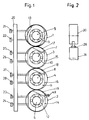
- FIG. 1 shows two synchronously driven plate cylinders 1 and 2 and blanket cylinders 3 and 4, which are mounted in side walls, not shown, in the usual way.
- Support elements 13 to 16 are shown on the axes 5 to 8 respectively assigned to the individual cylinders 1 to 4.
- the support elements 13 to 16 are each mounted on a bearing 9 to 12.
- some of the support elements 13 to 16, here the support elements 14, 15 and 16 have an inclined area, on each of which a stop is slidably arranged. These are the stops 17, 18 and 19 on the support elements 15, 16 and 14.
- the stops 17 to 1 ' 9 can be moved on the inclined plane with a corresponding adjusting device.
- an adjusting screw 49 was only shown in FIG. 1 on the support element 14, with which the stop 19 can be moved on the inclined plane, so that a height adjustment of the support element is possible.
- the contact pressure to the adjacent support element 16 can be set and the rolling conditions of the opposing cylinders can be taken into account in this setting so that they are optimized.
- the support elements 13 to 16 can be rotated on the axes 5 to 8.
- Each setting segment is assigned two setscrews in the embodiment described here, e.g. B. the support element 13, the set screws 21 and 22.
- the support elements can be rotated with the help of the set screws so that damaged areas get outside the contact area.
- FIG. 2 A further possible embodiment of the support elements is shown in FIG. 2.
- the support element 30 in FIG. 2 is provided with an adjustable pressure screw 29 which can be adjusted against a support element 31 arranged on an adjacent axis.
- the support elements In order to suppress bending vibrations, the support elements must be set to a fixed height, their dimensions preferably corresponding to the pitch circle diameter of the drive gears used in each case.
- FIG. 3 shows rubber blanket cylinders 34 and 35 mounted in parallel in side walls, not shown, with plate cylinders 32 and 33.
- a paper web 36 to be printed is passed between the rubber blanket cylinders 34 and 35 in a known manner.
- bearer rings 41, 42, 43 and 44 are mounted on the cylinder axes 37, 38, 39 and 40 of the cylinders 32, 34, 35 and 33 on bearings 45, 46, 47 and 48.
- This exemplary embodiment thus shows that bearer rings, which are arranged via bearings on the cylinder axes, are advantageously used as support elements to suppress the bending vibrations.
Landscapes
- Engineering & Computer Science (AREA)
- Mechanical Engineering (AREA)
- Rotary Presses (AREA)
Applications Claiming Priority (2)
| Application Number | Priority Date | Filing Date | Title |
|---|---|---|---|
| DE19792926765 DE2926765A1 (de) | 1979-07-03 | 1979-07-03 | Vorrichtung zur unterdrueckung von biegeschwingungen in rotations-offsetdruckmaschinen |
| DE2926765 | 1979-07-03 |
Publications (1)
| Publication Number | Publication Date |
|---|---|
| EP0021006A1 true EP0021006A1 (fr) | 1981-01-07 |
Family
ID=6074767
Family Applications (1)
| Application Number | Title | Priority Date | Filing Date |
|---|---|---|---|
| EP80102698A Withdrawn EP0021006A1 (fr) | 1979-07-03 | 1980-05-16 | Dispositif pour limiter les oscillations de flexion dans les machines d'impression rotatives en offset |
Country Status (2)
| Country | Link |
|---|---|
| EP (1) | EP0021006A1 (fr) |
| DE (1) | DE2926765A1 (fr) |
Cited By (5)
| Publication number | Priority date | Publication date | Assignee | Title |
|---|---|---|---|---|
| FR2527518A1 (fr) * | 1982-06-01 | 1983-12-02 | Carrier Claude | Machine a imprimer dont les cylindres comportent des bagues d'espacement |
| US20160001544A1 (en) * | 2013-02-18 | 2016-01-07 | Tresu A/S | Anti-bouncing printing roller/sleeve |
| CN107438521A (zh) * | 2015-03-12 | 2017-12-05 | 汉诺威莱布尼兹大学 | 印刷辊、特别是柔性印刷辊 |
| EP3287281A1 (fr) * | 2016-08-25 | 2018-02-28 | Gallus Druckmaschinen GmbH | Outil d'usinage et machine à imprimer d'étiquettes pourvue d'un tel outil d'usinage |
| EP3287280A1 (fr) * | 2016-08-25 | 2018-02-28 | Gallus Druckmaschinen GmbH | Outil d'usinage et machine à imprimer d'étiquettes pourvue d'un tel outil d'usinage |
Families Citing this family (1)
| Publication number | Priority date | Publication date | Assignee | Title |
|---|---|---|---|---|
| DE3317746C2 (de) * | 1983-05-16 | 1986-10-09 | Jürgen 1000 Berlin Schulz | Druckwerk und Verfahren zum Drucken |
Citations (4)
| Publication number | Priority date | Publication date | Assignee | Title |
|---|---|---|---|---|
| US2079001A (en) * | 1933-09-15 | 1937-05-04 | Goss Printing Press Co Ltd | Printing press |
| US2362069A (en) * | 1942-06-01 | 1944-11-07 | Hoe & Co R | Printing cylinder bearer |
| US3256812A (en) * | 1962-08-16 | 1966-06-21 | Goebel Gmbh Maschf | Printing machines |
| DE2736175A1 (de) * | 1977-08-11 | 1979-02-22 | Koenig & Bauer Ag | Druckwerk |
-
1979
- 1979-07-03 DE DE19792926765 patent/DE2926765A1/de not_active Ceased
-
1980
- 1980-05-16 EP EP80102698A patent/EP0021006A1/fr not_active Withdrawn
Patent Citations (4)
| Publication number | Priority date | Publication date | Assignee | Title |
|---|---|---|---|---|
| US2079001A (en) * | 1933-09-15 | 1937-05-04 | Goss Printing Press Co Ltd | Printing press |
| US2362069A (en) * | 1942-06-01 | 1944-11-07 | Hoe & Co R | Printing cylinder bearer |
| US3256812A (en) * | 1962-08-16 | 1966-06-21 | Goebel Gmbh Maschf | Printing machines |
| DE2736175A1 (de) * | 1977-08-11 | 1979-02-22 | Koenig & Bauer Ag | Druckwerk |
Cited By (10)
| Publication number | Priority date | Publication date | Assignee | Title |
|---|---|---|---|---|
| FR2527518A1 (fr) * | 1982-06-01 | 1983-12-02 | Carrier Claude | Machine a imprimer dont les cylindres comportent des bagues d'espacement |
| US20160001544A1 (en) * | 2013-02-18 | 2016-01-07 | Tresu A/S | Anti-bouncing printing roller/sleeve |
| US10011106B2 (en) * | 2013-02-18 | 2018-07-03 | Tresu A/S | Anti-bouncing printing roller/sleeve |
| CN107438521A (zh) * | 2015-03-12 | 2017-12-05 | 汉诺威莱布尼兹大学 | 印刷辊、特别是柔性印刷辊 |
| CN107438521B (zh) * | 2015-03-12 | 2019-06-21 | 汉诺威莱布尼兹大学 | 印刷辊、特别是柔性印刷辊 |
| EP3287281A1 (fr) * | 2016-08-25 | 2018-02-28 | Gallus Druckmaschinen GmbH | Outil d'usinage et machine à imprimer d'étiquettes pourvue d'un tel outil d'usinage |
| EP3287280A1 (fr) * | 2016-08-25 | 2018-02-28 | Gallus Druckmaschinen GmbH | Outil d'usinage et machine à imprimer d'étiquettes pourvue d'un tel outil d'usinage |
| CN107776182A (zh) * | 2016-08-25 | 2018-03-09 | 捷拉斯印刷机械有限公司 | 加工机械和具有这类加工机械的标签印刷机 |
| CN107776181A (zh) * | 2016-08-25 | 2018-03-09 | 捷拉斯印刷机械有限公司 | 加工机械和具有这类加工机械的标签印刷机 |
| CN107776182B (zh) * | 2016-08-25 | 2020-12-22 | 捷拉斯印刷机械有限公司 | 加工机械和具有这类加工机械的标签印刷机 |
Also Published As
| Publication number | Publication date |
|---|---|
| DE2926765A1 (de) | 1981-01-22 |
Similar Documents
| Publication | Publication Date | Title |
|---|---|---|
| DE4021895C2 (de) | Druckeinheit einer Offsetdruckmaschine zur Durchführung eines fliegenden Druckplattenwechsels | |
| EP0764523A1 (fr) | Dispositif d'impression pour l'impression indirecte | |
| EP1291175B1 (fr) | Cylindre porte-plaque pour plusieurs images | |
| EP0943433B1 (fr) | Unité d'impression pour une machine à imprimer, en particulier une machine rotative d'impression offset | |
| DE2130278C3 (de) | Druckeinheit einer Rollenrotationsdruckmaschine zum wahlweisen Hoch- oder Flachdruck | |
| DE9116367U1 (de) | Zylinder für die Papierführung an Bogenrotationsdruckmaschinen | |
| DE3529680C2 (fr) | ||
| EP0180807B1 (fr) | Dispositif d'encrage pour une rotative, notamment une rotative offset | |
| DE2033836B2 (de) | Rollen-Rotationsdruckmaschine | |
| DE1236529B (de) | Vorrichtung zur Lagerung sowie zum An- und Abstellen des mittleren Zylinders eines Dreizylinderdruckwerks | |
| CH647980A5 (en) | Forme cylinder for offset rotary printing machines | |
| DE10132156B4 (de) | Bahnstabilisierung zur berührungslosen Bahnführung bei fliegend wechselbaren Druckeinheiten | |
| EP0534160B1 (fr) | Machine à imprimer rotative | |
| DE69400707T2 (de) | Einrichtung zum verstellen des abstandes zwischen zylinderachsen in einer druckmaschine | |
| DE2926765A1 (de) | Vorrichtung zur unterdrueckung von biegeschwingungen in rotations-offsetdruckmaschinen | |
| EP0741024B1 (fr) | Dispositif pour serrer et séparer des rouleaux | |
| DE1241464B (de) | Einrichtung an einer Rotationsdruckmaschine zum Schraegstellen der Achse des Formzylinders gegenueber derjenigen des mit ihm zusammenwirkenden Druckwerkzylinders | |
| DE3317746C2 (de) | Druckwerk und Verfahren zum Drucken | |
| DE2713994A1 (de) | Bogenhaltevorrichtung einer bogen- rotations-druckmaschine, welche den druckbogen geringfuegig zu verformen vermag | |
| DE4436584C2 (de) | Plattenzylinderlagerung | |
| DE4433999A1 (de) | Bogenführende Trommel für Rotationsdruckmaschinen | |
| DE4401289C2 (de) | Zylinderanstellvorrichtung | |
| EP1707361B1 (fr) | Rouleau applicateur pour un groupe d'impression offset | |
| DE3115141A1 (de) | Vorrichtung zum diagonalverstellen eines zylinders einer druckmaschine, vorzugsweise des plattenzylinders einer bogenrotations-offsetdruckmaschine | |
| CH687603A5 (de) | Anordnung zum Einstellen des Lagerspiels bei Zylindern von Druckmaschinen. |
Legal Events
| Date | Code | Title | Description |
|---|---|---|---|
| PUAI | Public reference made under article 153(3) epc to a published international application that has entered the european phase |
Free format text: ORIGINAL CODE: 0009012 |
|
| AK | Designated contracting states |
Designated state(s): CH DE FR GB |
|
| 17P | Request for examination filed |
Effective date: 19810121 |
|
| STAA | Information on the status of an ep patent application or granted ep patent |
Free format text: STATUS: THE APPLICATION HAS BEEN WITHDRAWN |
|
| 18W | Application withdrawn |
Withdrawal date: 19820410 |
|
| RIN1 | Information on inventor provided before grant (corrected) |
Inventor name: FISCHER, HERMANN |