EP0021045A1 - Four à micro-ondes - Google Patents
Four à micro-ondes Download PDFInfo
- Publication number
- EP0021045A1 EP0021045A1 EP80102831A EP80102831A EP0021045A1 EP 0021045 A1 EP0021045 A1 EP 0021045A1 EP 80102831 A EP80102831 A EP 80102831A EP 80102831 A EP80102831 A EP 80102831A EP 0021045 A1 EP0021045 A1 EP 0021045A1
- Authority
- EP
- European Patent Office
- Prior art keywords
- cavity
- improvement according
- microwave
- shelf
- mounting
- Prior art date
- Legal status (The legal status is an assumption and is not a legal conclusion. Google has not performed a legal analysis and makes no representation as to the accuracy of the status listed.)
- Granted
Links
- 125000006850 spacer group Chemical group 0.000 claims description 3
- 230000008878 coupling Effects 0.000 claims description 2
- 238000010168 coupling process Methods 0.000 claims description 2
- 238000005859 coupling reaction Methods 0.000 claims description 2
- 238000010411 cooking Methods 0.000 description 11
- 238000012986 modification Methods 0.000 description 3
- 230000004048 modification Effects 0.000 description 3
- 238000012360 testing method Methods 0.000 description 2
- 239000000919 ceramic Substances 0.000 description 1
- 239000002184 metal Substances 0.000 description 1
- 230000001902 propagating effect Effects 0.000 description 1
Images
Classifications
-
- H—ELECTRICITY
- H05—ELECTRIC TECHNIQUES NOT OTHERWISE PROVIDED FOR
- H05B—ELECTRIC HEATING; ELECTRIC LIGHT SOURCES NOT OTHERWISE PROVIDED FOR; CIRCUIT ARRANGEMENTS FOR ELECTRIC LIGHT SOURCES, IN GENERAL
- H05B6/00—Heating by electric, magnetic or electromagnetic fields
- H05B6/64—Heating using microwaves
- H05B6/74—Mode transformers or mode stirrers
- H05B6/745—Rotatable stirrers
-
- H—ELECTRICITY
- H05—ELECTRIC TECHNIQUES NOT OTHERWISE PROVIDED FOR
- H05B—ELECTRIC HEATING; ELECTRIC LIGHT SOURCES NOT OTHERWISE PROVIDED FOR; CIRCUIT ARRANGEMENTS FOR ELECTRIC LIGHT SOURCES, IN GENERAL
- H05B6/00—Heating by electric, magnetic or electromagnetic fields
- H05B6/64—Heating using microwaves
- H05B6/6402—Aspects relating to the microwave cavity
Definitions
- This invention relates to microwave ovens and in particular to an improved energy feed system for such ovens.
- microwave ovens incorporate a magnetron as a microwave energy source feeding or propagating energy into a resonant cavity, with the food to be cooked being placed within the cavity.
- the feed system includes means for optimally coupling and distributing energy from the magnetron to the cavity. It is of course desirable to obtain a good energy distribution, or as commonly known in the trade a good cooking pattern, so as to minimize any "hot spots” or “cold spots” in the oven.
- an improved feed system has been provided for a microwave oven.
- the magnetron tube supplying microwave energy is mounted to a shelf which extends into but not more than half the distance between two opposing cavity walls, with the end of the shelf termininating adjacent a pair of rotating stirrer blades.
- the shelf end adjacent the stirrer blades includes a pair of adjacent arcuate sections. Each of the arcuate shelf sections conforms to the rotational arc circumscribed by the stirrer blades.
- a tuning stub is mounted to the shelf portion projecting into the cavity.
- the tuning stub position, diameter and height may be adjusted in a manner well-known in the art to obtain maximum power output from the magnetron.
- the portion of the shelf projecting into the cavity which forms a waveguide launching section for the microwave energy, can be formed of a separate plate mounted to the interior of the microwave cavity and at a height level with the shelf supporting the magnetron.
- the plate size can either be attached to the two remaining opposed cavity walls or left unattached as desired.
- the launcher plate may be spacially mounted to the cavity wall adjacent the magnetron by means of a plurality of conductive spacer mounting elements.
- Each embodiment incorporated the magnetron launcher shelf extending not more than halfway into the cavity with the free end terminating in arcuate sections corresponding to the arc circumscribed by the rotating stirrer blades, and with the clearance between the stirrer blades and the launcher edge being greater than 0.25 inch and less than 0.75 inch.
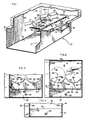
- microwave oven apparatus 10 including a resonant microwave cavity 12 defined between respective opposite side walls 14, 16, 18, 20, bottom 22 and top 24. Items non-essential for this description have been omitted for clarity. That is, the ceramic shelf, door, choke seal, power supply, controller and outer wrap normally associated with a microwave oven have been omitted.
- a microwave energy source 26 containing a magnetron tube supplies microwave energy to the cavity 12 through a radiating element 28 extending through aperture 30 in a mounting shelf 32.
- the mounting shelf 32 extends transversely outwardly from wall 14 with respect to cavity 12 and provides means for mounting an enclosure containing the magnetron tube.
- a pair of mode stirrers such as a pair of rotating fan-like stirrer blades 34 and 36 are located intermediate microwave cavity 12 and radiating element 28 so as to scatter the microwave energy throughout the cavity in a manner well-known in the art.
- the stirrer blades 34 and 36 may be rotated by means of suitable motors (not shown) drivingly connected to shafts coinciding with the respective axes of rotation 38, 40 in a manner well-knrwn in the art.
- the stirrer motor may for instance be mounted above and to the top wall 24 with the respective drive shafts extending through the wall to coincide with the axes 38 and 40 and connect to the respective blades 34, 36.
- the blades 34, 36 may be rotated by a suitable air flow supplied from a blower in a manner well-known in the art.
- the outer perimeters of the stirrer blades 34 and 36 circumscribe circular paths 42 and 44 illustrated in the dashed lines of Figure 2, and axes 38 and 40 are midway between cavity walls 14 and 16.
- An extension plate 46 of shelf 32 includes one end 48 mounted to cavity wall 14 by means of three metal spacers 50. Shelf extension 46 acts as a microwave launching portion aiding in feeding microwave energy from the magnetron to the cavity. Opposite end 52 of shelf extension 46 extends into cavity 12 and terminates before crossing the center line of the cavity defined between cavity walls 14 and 16 as illustrated in Figure 2. Two other respectively opposite sides 54, 56 extend along and are substantially adjacent to respective cavity walls 18 and 20. The bottoms of stirrer blades 34 and 36 lie approximately in the plane of plate 46.
- End 52 has a pair of circular cut-outs, specifically arcuate sections 58 and 60, matching the circular paths 42 and 44 circumscribed by the rotating stirrer blades.
- a tuning stub 62 is mounted by suitable means such as threads through an aperture provided in shelf extension 46 so that the height of the tuning stub above the shelf can be posi- tionably adjusted.
- the tuning stub diameter and position on plate 46, along with the height adjustment of the stub are experimentally determined so as to obtain maximum power output from the microwave energy source 26.
- the improved feed section including the shelf extension 46 acting as a microwave launching portion provides a significantly improved cooking pattern when compared to the prior art.
- the clearance or spacial distance indicated by reference numerals 64, 66 between the stirrer blades and the arcuate perimeters 58, 60 should be greater than 0.25 inch and less than 0.75 inch to obtain the best cooking pattern performance.
- FIG 3 and 4 Two alternative embodiments of the improved microwave feed system of the present invention are illustrated in Figure 3 and 4. It has been determined experimentally that the use of these alternative embodiments results in microwave oven cooking patterns substantially identical to those obtained in connection with the embodiment shown in Figures 1 and 2.
- an edge radius 68 and 70 is provided in the modified launching plate or extension shelf 72.
- launching plate or shelf extension 74 includes sides 76, 78 and 80 which are mounted respectively to cavity walls 14, 18 and 20.
- the alternative launching plate 74 also includes similar arcuate sections such as arcuate sections 58, 60 illustrated in connection with Figures 1-3.
- the arcuate sections 58 and 60 may be slotted or apertured to mount brackets supporting the stirrer blades, and as indicated previously, the blades may be rotated by an airstream directed against the blades.
- such modifications would normally require a compensating adjustment in the size and position of tuning stub 62 on the lsunhing pltte. This compensation can, of course, be readily provided by those skilled in the art.
Landscapes
- Physics & Mathematics (AREA)
- Electromagnetism (AREA)
- Engineering & Computer Science (AREA)
- Power Engineering (AREA)
- Constitution Of High-Frequency Heating (AREA)
Applications Claiming Priority (2)
| Application Number | Priority Date | Filing Date | Title |
|---|---|---|---|
| US50707 | 1979-06-21 | ||
| US06/050,707 US4249058A (en) | 1979-06-21 | 1979-06-21 | Feed system for a microwave oven |
Publications (2)
| Publication Number | Publication Date |
|---|---|
| EP0021045A1 true EP0021045A1 (fr) | 1981-01-07 |
| EP0021045B1 EP0021045B1 (fr) | 1983-05-25 |
Family
ID=21966909
Family Applications (1)
| Application Number | Title | Priority Date | Filing Date |
|---|---|---|---|
| EP80102831A Expired EP0021045B1 (fr) | 1979-06-21 | 1980-05-21 | Four à micro-ondes |
Country Status (4)
| Country | Link |
|---|---|
| US (1) | US4249058A (fr) |
| EP (1) | EP0021045B1 (fr) |
| CA (1) | CA1131714A (fr) |
| DE (1) | DE3063446D1 (fr) |
Cited By (2)
| Publication number | Priority date | Publication date | Assignee | Title |
|---|---|---|---|---|
| EP0370811A3 (fr) * | 1988-11-24 | 1991-12-18 | New World Domestic Appliances Limited | Fours à micro-ondes |
| GB2291322A (en) * | 1994-07-12 | 1996-01-17 | Samsung Electronics Co Ltd | Microwave oven |
Families Citing this family (4)
| Publication number | Priority date | Publication date | Assignee | Title |
|---|---|---|---|---|
| KR100206366B1 (ko) * | 1996-12-27 | 1999-07-01 | 전주범 | 전자레인지의 고주파 분산구조 |
| KR100448541B1 (ko) * | 2001-12-04 | 2004-09-13 | 삼성전자주식회사 | 전자렌지 |
| KR20030096542A (ko) * | 2002-06-14 | 2003-12-31 | 삼성전자주식회사 | 전자렌지 |
| US10004115B2 (en) * | 2016-06-13 | 2018-06-19 | The Markov Corporation | Electronic oven with reflective energy steering |
Citations (5)
| Publication number | Priority date | Publication date | Assignee | Title |
|---|---|---|---|---|
| US3339054A (en) * | 1964-04-20 | 1967-08-29 | Gen Motors Corp | Electronic oven |
| US3373259A (en) * | 1965-03-26 | 1968-03-12 | Lyons & Co Ltd J | Electronic oven |
| US3813918A (en) * | 1971-12-23 | 1974-06-04 | Ramex Co | Methods and apparatus using microwaves for material characteristics measurements |
| US3949184A (en) * | 1975-05-02 | 1976-04-06 | Raytheon Company | Folding microwave searing and browning means |
| FR2321227A1 (fr) * | 1975-03-31 | 1977-03-11 | Amana Refrigeration Inc | Joint de porte de four a hyperfrequences |
Family Cites Families (6)
| Publication number | Priority date | Publication date | Assignee | Title |
|---|---|---|---|---|
| US3364332A (en) * | 1964-03-20 | 1968-01-16 | Philips Corp | Arrangement in microwave stoves |
| US3526737A (en) * | 1967-03-20 | 1970-09-01 | Varian Associates | Microwave heating apparatus |
| US3758737A (en) * | 1972-06-13 | 1973-09-11 | Amana Refrigeration Inc | Waveguide filter for microwave heating apparatus |
| US3991295A (en) * | 1974-05-20 | 1976-11-09 | Matsushita Electric Industrial Co., Ltd. | Microwave oven with symmetrically positioned microwave stirrers |
| US4065654A (en) * | 1975-12-01 | 1977-12-27 | Chemetron Corporation | Microwave oven adjusting (energy distribution) and tuning arrangement |
| JPS5312535A (en) * | 1976-07-20 | 1978-02-04 | Toshiba Corp | Microwave heating unit |
-
1979
- 1979-06-21 US US06/050,707 patent/US4249058A/en not_active Expired - Lifetime
-
1980
- 1980-05-21 EP EP80102831A patent/EP0021045B1/fr not_active Expired
- 1980-05-21 DE DE8080102831T patent/DE3063446D1/de not_active Expired
- 1980-06-09 CA CA353,583A patent/CA1131714A/fr not_active Expired
Patent Citations (5)
| Publication number | Priority date | Publication date | Assignee | Title |
|---|---|---|---|---|
| US3339054A (en) * | 1964-04-20 | 1967-08-29 | Gen Motors Corp | Electronic oven |
| US3373259A (en) * | 1965-03-26 | 1968-03-12 | Lyons & Co Ltd J | Electronic oven |
| US3813918A (en) * | 1971-12-23 | 1974-06-04 | Ramex Co | Methods and apparatus using microwaves for material characteristics measurements |
| FR2321227A1 (fr) * | 1975-03-31 | 1977-03-11 | Amana Refrigeration Inc | Joint de porte de four a hyperfrequences |
| US3949184A (en) * | 1975-05-02 | 1976-04-06 | Raytheon Company | Folding microwave searing and browning means |
Cited By (2)
| Publication number | Priority date | Publication date | Assignee | Title |
|---|---|---|---|---|
| EP0370811A3 (fr) * | 1988-11-24 | 1991-12-18 | New World Domestic Appliances Limited | Fours à micro-ondes |
| GB2291322A (en) * | 1994-07-12 | 1996-01-17 | Samsung Electronics Co Ltd | Microwave oven |
Also Published As
| Publication number | Publication date |
|---|---|
| DE3063446D1 (en) | 1983-07-07 |
| CA1131714A (fr) | 1982-09-14 |
| EP0021045B1 (fr) | 1983-05-25 |
| US4249058A (en) | 1981-02-03 |
Similar Documents
| Publication | Publication Date | Title |
|---|---|---|
| US4144436A (en) | Microwave oven excitation system for promoting uniformity of energy distribution | |
| US4476362A (en) | High frequency heating apparatus | |
| US4335290A (en) | Microwave oven blower radiator | |
| CA1197565A (fr) | Four a micro-ondes avec systeme d'excitation a double alimentation | |
| US4455467A (en) | Metal rack for microwave oven | |
| CA1081795A (fr) | Four a micro-ondes a plateau rotatif | |
| EP0148562B1 (fr) | Unité de chauffage à haute-fréquence | |
| CA1068788A (fr) | Systeme d'alimentation d'energie pour four a micro-ondes et traditionnel | |
| US4223194A (en) | Microwave oven with means for modifying energy distribution therein | |
| US4642435A (en) | Rotating slot antenna arrangement for microwave oven | |
| US4508946A (en) | Microwave oven with rotary antenna | |
| US4249058A (en) | Feed system for a microwave oven | |
| EP0573750B1 (fr) | Four à micro-ondes | |
| US4496814A (en) | Microwave excitation system | |
| US4262183A (en) | Combination microwave/forced convection oven | |
| KR950013271B1 (ko) | 마이크로파 오븐용 삼각형 안테나 어레이 | |
| EP0265775B1 (fr) | Four à micro-ondes avec élément chauffant | |
| CA1259106A (fr) | Antenne tournante pour four a micro-ondes | |
| US4501945A (en) | Microwave oven provided with turntable | |
| US3430022A (en) | Microwave oven | |
| GB2119210A (en) | Microwave oven with rotary antennas | |
| KR0127628Y1 (ko) | 전자렌지의 고주파 분산장치 | |
| KR900002163Y1 (ko) | 전자레인지의 균일 가열장치 | |
| GB2098838A (en) | Microwave oven | |
| JPS6330887Y2 (fr) |
Legal Events
| Date | Code | Title | Description |
|---|---|---|---|
| PUAI | Public reference made under article 153(3) epc to a published international application that has entered the european phase |
Free format text: ORIGINAL CODE: 0009012 |
|
| AK | Designated contracting states |
Designated state(s): DE FR GB IT NL |
|
| ITCL | It: translation for ep claims filed |
Representative=s name: SOCIETA' ITALIANA BREVETTI S.P.A. |
|
| DET | De: translation of patent claims | ||
| 17P | Request for examination filed |
Effective date: 19810701 |
|
| ITF | It: translation for a ep patent filed | ||
| GRAA | (expected) grant |
Free format text: ORIGINAL CODE: 0009210 |
|
| RAP1 | Party data changed (applicant data changed or rights of an application transferred) |
Owner name: LITTON SYSTEMS, INC. |
|
| AK | Designated contracting states |
Designated state(s): DE FR GB IT NL |
|
| ET | Fr: translation filed | ||
| REF | Corresponds to: |
Ref document number: 3063446 Country of ref document: DE Date of ref document: 19830707 |
|
| PGFP | Annual fee paid to national office [announced via postgrant information from national office to epo] |
Ref country code: DE Payment date: 19840321 Year of fee payment: 5 |
|
| PLBE | No opposition filed within time limit |
Free format text: ORIGINAL CODE: 0009261 |
|
| STAA | Information on the status of an ep patent application or granted ep patent |
Free format text: STATUS: NO OPPOSITION FILED WITHIN TIME LIMIT |
|
| 26N | No opposition filed | ||
| PG25 | Lapsed in a contracting state [announced via postgrant information from national office to epo] |
Ref country code: DE Effective date: 19900201 |
|
| ITTA | It: last paid annual fee | ||
| PGFP | Annual fee paid to national office [announced via postgrant information from national office to epo] |
Ref country code: FR Payment date: 19930316 Year of fee payment: 14 |
|
| PGFP | Annual fee paid to national office [announced via postgrant information from national office to epo] |
Ref country code: GB Payment date: 19930322 Year of fee payment: 14 |
|
| PGFP | Annual fee paid to national office [announced via postgrant information from national office to epo] |
Ref country code: NL Payment date: 19930531 Year of fee payment: 14 |
|
| PG25 | Lapsed in a contracting state [announced via postgrant information from national office to epo] |
Ref country code: GB Effective date: 19940521 |
|
| PG25 | Lapsed in a contracting state [announced via postgrant information from national office to epo] |
Ref country code: NL Effective date: 19941201 |
|
| NLV4 | Nl: lapsed or anulled due to non-payment of the annual fee | ||
| GBPC | Gb: european patent ceased through non-payment of renewal fee |
Effective date: 19940521 |
|
| PG25 | Lapsed in a contracting state [announced via postgrant information from national office to epo] |
Ref country code: FR Effective date: 19950131 |
|
| REG | Reference to a national code |
Ref country code: FR Ref legal event code: ST |