EP0021093B1 - Dispositif destiné à transmettre un rayonnement à une surface et à recevoir le rayonnement émanant de cette surface - Google Patents
Dispositif destiné à transmettre un rayonnement à une surface et à recevoir le rayonnement émanant de cette surface Download PDFInfo
- Publication number
- EP0021093B1 EP0021093B1 EP80102982A EP80102982A EP0021093B1 EP 0021093 B1 EP0021093 B1 EP 0021093B1 EP 80102982 A EP80102982 A EP 80102982A EP 80102982 A EP80102982 A EP 80102982A EP 0021093 B1 EP0021093 B1 EP 0021093B1
- Authority
- EP
- European Patent Office
- Prior art keywords
- radiation
- output
- receiving
- reflecting
- face
- Prior art date
- Legal status (The legal status is an assumption and is not a legal conclusion. Google has not performed a legal analysis and makes no representation as to the accuracy of the status listed.)
- Expired
Links
Images
Classifications
-
- H—ELECTRICITY
- H04—ELECTRIC COMMUNICATION TECHNIQUE
- H04N—PICTORIAL COMMUNICATION, e.g. TELEVISION
- H04N1/00—Scanning, transmission or reproduction of documents or the like, e.g. facsimile transmission; Details thereof
- H04N1/024—Details of scanning heads ; Means for illuminating the original
- H04N1/028—Details of scanning heads ; Means for illuminating the original for picture information pick-up
- H04N1/02815—Means for illuminating the original, not specific to a particular type of pick-up head
- H04N1/02845—Means for illuminating the original, not specific to a particular type of pick-up head using an elongated light source, e.g. tubular lamp, LED array
- H04N1/0285—Means for illuminating the original, not specific to a particular type of pick-up head using an elongated light source, e.g. tubular lamp, LED array in combination with at least one reflector which is in fixed relation to the light source
-
- G—PHYSICS
- G02—OPTICS
- G02B—OPTICAL ELEMENTS, SYSTEMS OR APPARATUS
- G02B19/00—Condensers, e.g. light collectors or similar non-imaging optics
- G02B19/0004—Condensers, e.g. light collectors or similar non-imaging optics characterised by the optical means employed
- G02B19/0028—Condensers, e.g. light collectors or similar non-imaging optics characterised by the optical means employed refractive and reflective surfaces, e.g. non-imaging catadioptric systems
-
- G—PHYSICS
- G02—OPTICS
- G02B—OPTICAL ELEMENTS, SYSTEMS OR APPARATUS
- G02B19/00—Condensers, e.g. light collectors or similar non-imaging optics
- G02B19/0033—Condensers, e.g. light collectors or similar non-imaging optics characterised by the use
- G02B19/0047—Condensers, e.g. light collectors or similar non-imaging optics characterised by the use for use with a light source
- G02B19/0052—Condensers, e.g. light collectors or similar non-imaging optics characterised by the use for use with a light source the light source comprising a laser diode
-
- G—PHYSICS
- G02—OPTICS
- G02B—OPTICAL ELEMENTS, SYSTEMS OR APPARATUS
- G02B19/00—Condensers, e.g. light collectors or similar non-imaging optics
- G02B19/0033—Condensers, e.g. light collectors or similar non-imaging optics characterised by the use
- G02B19/0076—Condensers, e.g. light collectors or similar non-imaging optics characterised by the use for use with a detector
-
- H—ELECTRICITY
- H04—ELECTRIC COMMUNICATION TECHNIQUE
- H04N—PICTORIAL COMMUNICATION, e.g. TELEVISION
- H04N1/00—Scanning, transmission or reproduction of documents or the like, e.g. facsimile transmission; Details thereof
- H04N1/024—Details of scanning heads ; Means for illuminating the original
- H04N1/028—Details of scanning heads ; Means for illuminating the original for picture information pick-up
- H04N1/02815—Means for illuminating the original, not specific to a particular type of pick-up head
- H04N1/02845—Means for illuminating the original, not specific to a particular type of pick-up head using an elongated light source, e.g. tubular lamp, LED array
- H04N1/02855—Means for illuminating the original, not specific to a particular type of pick-up head using an elongated light source, e.g. tubular lamp, LED array in combination with a light guide, e.g. optical fibre, glass plate
-
- H—ELECTRICITY
- H04—ELECTRIC COMMUNICATION TECHNIQUE
- H04N—PICTORIAL COMMUNICATION, e.g. TELEVISION
- H04N1/00—Scanning, transmission or reproduction of documents or the like, e.g. facsimile transmission; Details thereof
- H04N1/024—Details of scanning heads ; Means for illuminating the original
- H04N1/028—Details of scanning heads ; Means for illuminating the original for picture information pick-up
- H04N1/02815—Means for illuminating the original, not specific to a particular type of pick-up head
- H04N1/02845—Means for illuminating the original, not specific to a particular type of pick-up head using an elongated light source, e.g. tubular lamp, LED array
- H04N1/02865—Means for illuminating the original, not specific to a particular type of pick-up head using an elongated light source, e.g. tubular lamp, LED array using an array of light sources or a combination of such arrays, e.g. an LED bar
-
- H—ELECTRICITY
- H04—ELECTRIC COMMUNICATION TECHNIQUE
- H04N—PICTORIAL COMMUNICATION, e.g. TELEVISION
- H04N1/00—Scanning, transmission or reproduction of documents or the like, e.g. facsimile transmission; Details thereof
- H04N1/024—Details of scanning heads ; Means for illuminating the original
- H04N1/028—Details of scanning heads ; Means for illuminating the original for picture information pick-up
- H04N1/02815—Means for illuminating the original, not specific to a particular type of pick-up head
- H04N1/02845—Means for illuminating the original, not specific to a particular type of pick-up head using an elongated light source, e.g. tubular lamp, LED array
- H04N1/0287—Means for illuminating the original, not specific to a particular type of pick-up head using an elongated light source, e.g. tubular lamp, LED array using a tubular lamp or a combination of such lamps
-
- H—ELECTRICITY
- H04—ELECTRIC COMMUNICATION TECHNIQUE
- H04N—PICTORIAL COMMUNICATION, e.g. TELEVISION
- H04N1/00—Scanning, transmission or reproduction of documents or the like, e.g. facsimile transmission; Details thereof
- H04N1/024—Details of scanning heads ; Means for illuminating the original
- H04N1/028—Details of scanning heads ; Means for illuminating the original for picture information pick-up
- H04N1/03—Details of scanning heads ; Means for illuminating the original for picture information pick-up with photodetectors arranged in a substantially linear array
- H04N1/031—Details of scanning heads ; Means for illuminating the original for picture information pick-up with photodetectors arranged in a substantially linear array the photodetectors having a one-to-one and optically positive correspondence with the scanned picture elements, e.g. linear contact sensors
- H04N1/0311—Details of scanning heads ; Means for illuminating the original for picture information pick-up with photodetectors arranged in a substantially linear array the photodetectors having a one-to-one and optically positive correspondence with the scanned picture elements, e.g. linear contact sensors using an array of elements to project the scanned image elements onto the photodetectors
- H04N1/0312—Details of scanning heads ; Means for illuminating the original for picture information pick-up with photodetectors arranged in a substantially linear array the photodetectors having a one-to-one and optically positive correspondence with the scanned picture elements, e.g. linear contact sensors using an array of elements to project the scanned image elements onto the photodetectors using an array of optical fibres or rod-lenses
Definitions
- the invention relates to optical apparatus for generating a scanning slit of radiation, and more particularly, to a device that focuses input radiation by intemal reflection to form an associated output slit image.
- Lines of print or other characters may be electronically read by illuminating the characters with an intense slit of light and measuring the variations in the intensity of the reflected light.
- optical read/write head that employs a plurality of optical fibers or a light pipe to carry light from a source of illumination to a small portion of a surface under examination.
- An optical fiber is employed to carry the reflected light from the Irradiated surface to a detector.
- optical fibers are employed to carry light to a box having internally reflecting surfaces that diffuse the light and direct the light out of a transparent wall of the box.
- the disclosed internally reflecting light box is not used for irradiating a scanned surface or picking up reflected radiation from the surface.
- Another object of the invention is to provide such an illumination and pickup apparatus that focuses the light from a relatively low intensity source of illumination by internal reflection to form a corresponding high intensity illuminating slit.
- the illumination and pickup device includes an internally reflecting ellipsoid element that is shaped to receive a light input at one of its focal lines and to focus the light by internal reflection to an intense illuminating slit at its other focal line.
- the light output end of the ellipsoid is cut in a circularly shaped cylindrical section having the focal line as its axis.
- An adjacent flat end portion of the ellipsoid rests on a surface to maintain the focal line in alignment with the surface.
- the shape of the cut-out section ensures that internally reflected light exits at all points normal to the circular cylindrical surface of the ellipsoid, thereby eliminating defocusing due to refraction at the interface between the surface of the ellipsoid and the surrounding air.
- the index of refraction of the material of the ellipsoid does not affect the focusing operation of the ellipsoid.
- Pickup optical fibers are affixed adjacent to the irradiating end of the ellipsoid for receiving the light that is reflected from the surface and transmitting the reflected light to a photodetector.
- An alternative embodiment of the invention includes an internally reflecting box, preferably a solid radiation transparent box, having top, bottom, side and back internally reflecting faces and a small, elongated output radiation transparent face in close proximity to a surface to be illuminated.
- a bundle of optical fibers conducts light from a light source into the interior of the block. The incident light is internally reflected and passed by the transparent face of the box to illuminate a confined area of a surface with high intensity light.
- Pickup optical fibers are embedded in the output radiation transparent face for receiving the light that is reflected from the surface and transmitting the reflected light to a photoconductor.
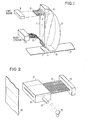
- Figure 1 illustrates a perspective view of an ellipsoidal illumination and pickup head in accordance with the invention.
- the ellipsoidal head 1 may be made of a light transparent material, for example, a clear plastic such as lucite and may be easily and inexpensively formed by molding.
- the curved wall 3 of the ellipsoidal head 1 is shaped to form a portion of an ellipse. It will be appreciated by those skilled in the art that there is defined for the ellipsoidal shape of Figure 1 an input focal line 5 and an output focal line 7 corresponding to the focal points of the stacked, confocal ellipses defined by the curved wall 3.
- a known geometrical property of an ellipse is that light emitted from one focal point of the ellipse is totally reflected from the wall of the ellipse, and is focused at the other focal point of the ellipse.
- a light source 9 for example, a light emitting diode
- the optical fibers carry the light from the light source 9 to the area of the input focal line 5 of the ellipsoidal head 1.
- a slot 15 may be formed at the input end of the ellipsoidal head 1 to receive the optical fibers 13 and to hold the ends of the optical fibers in position at the input focal line 5.
- the optical fibers may be maintained in position by gluing the fibers to the material of the ellipsoidal head 1.
- any light transmission means known in the optical art may be employed to carry light from the source 9 to a position along the input focal line 5.
- other light sources for example, an incandescent lamp, may be employed to supply light for the apparatus of the invention.
- the light source may be of relatively low intensity since the ellipsoidal head 1 serves to focus even a low intensity incident beam to a relatively sharp slit image.
- all exterior surfaces of the ellipsoidal head are covered with reflective material so that the radiation from the input focal line 5 may be internally reflected to the output focal line 7.
- the ellipsoidal head will operate in accordance with the invention if at least the exterior surface of the curved wall 3 is covered with reflective material.
- One means for providing a reflective coating to the ellipsoidal head 1 is to sputter aluminum on the outer surface of the head.
- the head 1 may be coated with a reflective aluminum paint.
- the irradiating end of the ellipsoidal head 1 is cut to form a circularly shaped cylindrical wall 17 having the output focal line 7 as its axis.
- the circularly shaped cylindrical wall 17 is not coated with reflective material since it is necessary for the internally reflected light to emerge from the cylindrical wall 17 to form an intense slit image at the focal line 7.
- the cylindrical wall 17 is shaped so that the internally reflected light from the input focal line 5 emerges at all points normal to the surface of the wall. Thus, refraction of light at the interface between the cylindrical wall 17 and the surrounding air is avoided and a sharp slit image is produced.
- the ellipsoidal head 1 may be placed so that a flat alignment end 19 abuts the surface to be examined, for example, a paper 21.
- a flat alignment end 19 lies in the same plane as the focal line 7 so that the focal line 7 is focused directly on the paper when the alignment end 7 abuts the paper.
- the ellipsoidal head 1 may be easily maintained in proper alignment with the paper 21 at all times.
- the ellipsoidal head 1 may be affixed to a transparent scanning surface and an article having coded marks may be moved across the scanning surface and scanned by the irradiating image at the focal line 7.
- the reflected radiation from the surface of the paper 21 is picked up by optical fibers 23 that are affixed, for example, by glue, to a flat surface of the ellipsoidal head 1.
- the optical fibers 23 are employed to carry the reflected light from the surface 21 to a corresponding photodetector 25, for example, a charge coupled device.
- the photodetector 25 is employed to generate electrical signals corresponding to the intensity of the light that is reflected from the paper 21.
- the electrical signals may be analyzed to determine the optical pattern on the irradiated portion of the paper.
- Figure 2 illustrates an alternative embodiment of the invention wherein a transparent block 27, for example, of lucite, is employed as a source of illumination and as a pickup head.
- Optical fibers 37 are embedded in the lucite block with the light pickup ends of the fibers positioned in the plane of a transparent face 29 of the block.
- the optical fibers may be easily embedded in the block if the block is formed by molding.
- the block may be assembled from two mating pieces having matching grooves. The optical fibers may be placed in position within the grooves of one piece and the other piece may then be glued into mating contact with the first piece to secure the fibers in place.
- each of the optical fibers 37 are painted with a non-reflective paint to ensure that each fiber receives light only from the exposed end adjacent the transparent face 29.
- the invention is intended to include an illumination and pickup head wherein the fibers are not painted.
- a light pipe or bundle of optical fibers 43 is affixed to the transparent light input area, for example, by gluing, and an associated light source 45, for example, a light emitting diode or an incandescent lamp, is operated to transmit light through the light pipe or bundle of optical fibers 43 to the interior of the lucite block 27.
- the transmitted light is internally reflected from the reflective walls of the lucite block 27 and is uniformly emitted from the transparent front wall 29 of the lucite block to Irradiate a surface, for example, a paper 49.
- the reflected light from the paper 49 is picked up by the optical fibers 37 and is transmitted by the fibers to a photodetector 51 that generates electrical signals corresponding to the intensity of the light.
- Illumination and pickup heads of Figures 1 and 2 need not be constructed from solid blocks of transparent material.
- the reflecting surfaces of the block 27 or the head 1 may be defined by walls having a reflective coating on an interior reflecting surface.
- an ellipsoidal head 1 having a major axis of 51 mm, a minor axis of 38 mm and a thickness of 8 mm may be conveniently used to illuminate and receive reflected light from characters on a sheet of paper.
- the invention is not limited to any particular dimensioning of the ellipsoidal head.
Landscapes
- Engineering & Computer Science (AREA)
- Multimedia (AREA)
- Signal Processing (AREA)
- Physics & Mathematics (AREA)
- General Physics & Mathematics (AREA)
- Optics & Photonics (AREA)
- Image Input (AREA)
- Investigating Materials By The Use Of Optical Means Adapted For Particular Applications (AREA)
- Character Input (AREA)
- Optical Elements Other Than Lenses (AREA)
- Optical Fibers, Optical Fiber Cores, And Optical Fiber Bundles (AREA)
Claims (10)
Applications Claiming Priority (2)
| Application Number | Priority Date | Filing Date | Title |
|---|---|---|---|
| US53680 | 1979-06-29 | ||
| US06/053,680 US4287414A (en) | 1979-06-29 | 1979-06-29 | Illumination and pick up apparatus |
Publications (2)
| Publication Number | Publication Date |
|---|---|
| EP0021093A1 EP0021093A1 (fr) | 1981-01-07 |
| EP0021093B1 true EP0021093B1 (fr) | 1983-05-11 |
Family
ID=21985839
Family Applications (1)
| Application Number | Title | Priority Date | Filing Date |
|---|---|---|---|
| EP80102982A Expired EP0021093B1 (fr) | 1979-06-29 | 1980-05-29 | Dispositif destiné à transmettre un rayonnement à une surface et à recevoir le rayonnement émanant de cette surface |
Country Status (5)
| Country | Link |
|---|---|
| US (1) | US4287414A (fr) |
| EP (1) | EP0021093B1 (fr) |
| JP (1) | JPS568102A (fr) |
| CA (1) | CA1148255A (fr) |
| DE (1) | DE3063082D1 (fr) |
Cited By (1)
| Publication number | Priority date | Publication date | Assignee | Title |
|---|---|---|---|---|
| US6438262B1 (en) | 1996-02-05 | 2002-08-20 | Mars Incorporated | Security document validation |
Families Citing this family (25)
| Publication number | Priority date | Publication date | Assignee | Title |
|---|---|---|---|---|
| US4441817A (en) * | 1980-07-29 | 1984-04-10 | Diffracto Ltd. | Electro-optical sensors with fiber optic bundles |
| US4515479A (en) * | 1980-07-29 | 1985-05-07 | Diffracto Ltd. | Electro-optical sensors with fiber optic bundles |
| NL8103599A (nl) * | 1981-07-30 | 1983-02-16 | Philips Nv | Inrichting voor het optisch aftasten van een document. |
| EP0077988B1 (fr) * | 1981-10-23 | 1986-03-19 | Kabushiki Kaisha Toshiba | Détecteur de densité d'image pour un dispositif de formation d'image |
| JPS5986785U (ja) * | 1982-11-30 | 1984-06-12 | 日本ビクター株式会社 | カラ−テレビジヨン撮像素子へのバイアス光付与装置 |
| US4530565A (en) * | 1982-12-20 | 1985-07-23 | The Perkin-Elmer Corporation | Optical transformer using curved strip waveguides to achieve a nearly unchanged F/number |
| DE3302800A1 (de) * | 1983-01-28 | 1984-08-02 | Fa. Carl Zeiss, 7920 Heidenheim | Abbildungssystem |
| US4647765A (en) * | 1983-10-08 | 1987-03-03 | Brother Industries, Ltd. | Image sensing head of image reading device having light shield and base plate disposed at end face thereof |
| CH690471A5 (de) * | 1988-04-18 | 2000-09-15 | Mars Inc | Einrichtung zum Erkennen der Echtheit von Dokumenten. |
| DE4031633A1 (de) * | 1990-10-05 | 1992-04-16 | Sick Optik Elektronik Erwin | Optische inspektionsvorrichtung |
| US5159656A (en) * | 1991-04-29 | 1992-10-27 | Advanced Technology Consortium, Inc. | Optical fiber scanning/imaging/printing system |
| US5335158A (en) * | 1992-05-21 | 1994-08-02 | Eastman Kodak Company | High efficiency linear light source |
| JP2778659B2 (ja) * | 1993-12-24 | 1998-07-23 | キヤノン株式会社 | 導光体及び照明装置及び画像読取装置 |
| US6268600B1 (en) | 1994-08-01 | 2001-07-31 | Matsushita Electric Industrial Co., Ltd. | Linear illumination device |
| US5969343A (en) * | 1995-08-24 | 1999-10-19 | Matsushita Electric Industrial Co., Ltd. | Linear illumination device |
| JP3368110B2 (ja) | 1995-08-01 | 2003-01-20 | キヤノン株式会社 | 光源装置及び光学機器 |
| DE19532877A1 (de) * | 1995-09-06 | 1997-03-13 | Giesecke & Devrient Gmbh | Vorrichtung zur linienförmigen Beleuchtung von Blattgut, wie z. B. Banknoten oder Wertpapiere |
| US5903403A (en) * | 1997-01-24 | 1999-05-11 | Hewlett-Packard Company | Imaging system using a compound elliptical concentrator |
| US6170973B1 (en) * | 1997-11-26 | 2001-01-09 | Cognex Corporation | Method and apparatus for wide-angle illumination in line-scanning machine vision devices |
| US6333779B1 (en) * | 1998-12-24 | 2001-12-25 | Canon Kabushiki Kaisha | Illumination apparatus using light guide |
| DE10108075A1 (de) * | 2001-02-20 | 2002-09-19 | Oce Document Technologies Gmbh | Vorrichtung und Verfahren zum zeilenförmigen Beleuchten eines Objektes mittels LEDs und eines elliptischen Spiegels |
| WO2003045048A2 (fr) * | 2001-11-23 | 2003-05-30 | Oce Document Technologies Gmbh | Dispositif et un procede pour balayer un document en utilisant le mouvement d'elevation et de rotation d'une camera |
| DE102006006031B4 (de) | 2005-04-20 | 2009-12-24 | Bürkert Werke GmbH & Co. KG | Elektromagneteinheit sowie Verfahren zur Herstellung einer solchen Elektromagneteinheit und eines Magnetgehäuses für eine solche Elektromagneteinheit |
| US7710570B2 (en) * | 2008-04-18 | 2010-05-04 | Avago Technologies Ecbu Ip (Singapore) Pte. Ltd. | Light pipe for low profile optical navigation systems |
| DE102009058244A1 (de) | 2009-12-14 | 2011-06-16 | Giesecke & Devrient Gmbh | Vorrichtung für die Untersuchung eines Gegenstands, vorzugsweise eines Wertdokuments, unter Verwendung optischer Strahlung |
Family Cites Families (13)
| Publication number | Priority date | Publication date | Assignee | Title |
|---|---|---|---|---|
| US3060806A (en) * | 1959-05-04 | 1962-10-30 | Bausch & Lomb | Image forming element |
| US3328589A (en) * | 1963-04-10 | 1967-06-27 | Jr Thomas G Ferguson | Photoelectric apparatus for providing pulsing signals including stacked plate focussing means |
| DE1199205B (de) | 1964-04-11 | 1965-08-26 | Quarzlampen Gmbh | Vorrichtung zum Einleiten von Licht in Glasfaserbuendel |
| US3643103A (en) * | 1970-03-16 | 1972-02-15 | Mohawk Data Sciences Corp | Light-conducting member for photoelectric code sensor |
| US3663083A (en) * | 1970-09-15 | 1972-05-16 | Columbia Broadcasting Systems | Light directing device having an elliptical reflecting face |
| JPS4879686A (fr) * | 1972-01-28 | 1973-10-25 | ||
| US3913568A (en) * | 1973-01-22 | 1975-10-21 | American Optical Corp | Nasopharyngoscope |
| US3956587A (en) * | 1973-02-20 | 1976-05-11 | Exxon Research And Engineering Company | Facsimile apparatus |
| JPS5423308Y2 (fr) * | 1973-08-09 | 1979-08-10 | ||
| DE2357721C3 (de) * | 1973-11-19 | 1979-02-22 | Hoechst Ag, 6000 Frankfurt | Anordnung für Beleuchtung und Abtastung in Projektionskopiereinrichtungen, insbesondere für elektrofotografische Kopiergeräte |
| JPS52123625A (en) * | 1976-04-09 | 1977-10-18 | Ricoh Co Ltd | Focusing optical system for electrophotographic copier |
| JPS52142916A (en) * | 1976-05-25 | 1977-11-29 | Kokusai Denshin Denwa Co Ltd | Recording system |
| DE2741715C2 (de) * | 1977-09-16 | 1979-10-11 | Hasco-Normalien Hasenclever & Co, 5880 Luedenscheid | Einrichtung zum Betrachten von Bearbeitungsstellen von in einer Flüssigkeit angeordneten Werkstücken |
-
1979
- 1979-06-29 US US06/053,680 patent/US4287414A/en not_active Expired - Lifetime
-
1980
- 1980-03-18 JP JP3349780A patent/JPS568102A/ja active Pending
- 1980-04-14 CA CA000349796A patent/CA1148255A/fr not_active Expired
- 1980-05-29 EP EP80102982A patent/EP0021093B1/fr not_active Expired
- 1980-05-29 DE DE8080102982T patent/DE3063082D1/de not_active Expired
Cited By (1)
| Publication number | Priority date | Publication date | Assignee | Title |
|---|---|---|---|---|
| US6438262B1 (en) | 1996-02-05 | 2002-08-20 | Mars Incorporated | Security document validation |
Also Published As
| Publication number | Publication date |
|---|---|
| CA1148255A (fr) | 1983-06-14 |
| DE3063082D1 (en) | 1983-06-16 |
| US4287414A (en) | 1981-09-01 |
| EP0021093A1 (fr) | 1981-01-07 |
| JPS568102A (en) | 1981-01-27 |
Similar Documents
| Publication | Publication Date | Title |
|---|---|---|
| EP0021093B1 (fr) | Dispositif destiné à transmettre un rayonnement à une surface et à recevoir le rayonnement émanant de cette surface | |
| US4760248A (en) | Portable laser diode scanning head | |
| US5247162A (en) | Portable laser diode scanning head having a focusing lens and an aperture | |
| US4603262A (en) | Optical device for detecting coded symbols | |
| US5504317A (en) | Optical reader | |
| US4652750A (en) | Optical device for detecting coded symbols | |
| US6628445B2 (en) | Coplanar camera scanning system | |
| US5075538A (en) | Portable laser diode scanning head | |
| US5468949A (en) | Portable laser diode scanning head | |
| US7784975B2 (en) | Apparatus for linear illumination of a moving product web | |
| JP2002507779A (ja) | 目標照明装置 | |
| AU763933B2 (en) | Laser focusing aperture and method | |
| US5825011A (en) | Handle like reading unit for use in code reading apparatus and having plural light reflectors and direct light shielding plate | |
| US7591576B2 (en) | Illuminator and image reader employing it | |
| US5362953A (en) | Reading apparatus with separate illumination and detection optical axes | |
| EP0919829A3 (fr) | Appareil de mesure de distance | |
| US6441928B1 (en) | Apparatus and method for reading a document using a waveguide formed in a substrate | |
| JP2711191B2 (ja) | 凹凸パターン読取装置 | |
| US6430339B1 (en) | Low profile waveguide system | |
| JP2001256430A (ja) | スキャナ | |
| JPH05308471A (ja) | 画像伝送ユニット | |
| JP2002269490A (ja) | 情報コード読取り装置 | |
| JPS59200915A (ja) | バ−コ−ド読取り装置 | |
| JPH0630194A (ja) | 走査装置用照明装置 | |
| GB2271031A (en) | Displacement encoder |
Legal Events
| Date | Code | Title | Description |
|---|---|---|---|
| PUAI | Public reference made under article 153(3) epc to a published international application that has entered the european phase |
Free format text: ORIGINAL CODE: 0009012 |
|
| AK | Designated contracting states |
Designated state(s): DE FR GB |
|
| 17P | Request for examination filed |
Effective date: 19810123 |
|
| GRAA | (expected) grant |
Free format text: ORIGINAL CODE: 0009210 |
|
| AK | Designated contracting states |
Designated state(s): DE FR GB |
|
| REF | Corresponds to: |
Ref document number: 3063082 Country of ref document: DE Date of ref document: 19830616 |
|
| ET | Fr: translation filed | ||
| PLBE | No opposition filed within time limit |
Free format text: ORIGINAL CODE: 0009261 |
|
| STAA | Information on the status of an ep patent application or granted ep patent |
Free format text: STATUS: NO OPPOSITION FILED WITHIN TIME LIMIT |
|
| 26N | No opposition filed | ||
| PGFP | Annual fee paid to national office [announced via postgrant information from national office to epo] |
Ref country code: GB Payment date: 19900404 Year of fee payment: 11 |
|
| PGFP | Annual fee paid to national office [announced via postgrant information from national office to epo] |
Ref country code: FR Payment date: 19900424 Year of fee payment: 11 |
|
| PGFP | Annual fee paid to national office [announced via postgrant information from national office to epo] |
Ref country code: DE Payment date: 19900529 Year of fee payment: 11 |
|
| PG25 | Lapsed in a contracting state [announced via postgrant information from national office to epo] |
Ref country code: GB Effective date: 19910529 |
|
| GBPC | Gb: european patent ceased through non-payment of renewal fee | ||
| PG25 | Lapsed in a contracting state [announced via postgrant information from national office to epo] |
Ref country code: FR Effective date: 19920131 |
|
| PG25 | Lapsed in a contracting state [announced via postgrant information from national office to epo] |
Ref country code: DE Effective date: 19920303 |
|
| REG | Reference to a national code |
Ref country code: FR Ref legal event code: ST |