EP0021970A1 - Steuerventil für ein durch Druckmittel betätigtes System - Google Patents
Steuerventil für ein durch Druckmittel betätigtes System Download PDFInfo
- Publication number
- EP0021970A1 EP0021970A1 EP19800400868 EP80400868A EP0021970A1 EP 0021970 A1 EP0021970 A1 EP 0021970A1 EP 19800400868 EP19800400868 EP 19800400868 EP 80400868 A EP80400868 A EP 80400868A EP 0021970 A1 EP0021970 A1 EP 0021970A1
- Authority
- EP
- European Patent Office
- Prior art keywords
- arms
- discharge
- arm
- chamber
- section
- Prior art date
- Legal status (The legal status is an assumption and is not a legal conclusion. Google has not performed a legal analysis and makes no representation as to the accuracy of the status listed.)
- Granted
Links
- 239000012530 fluid Substances 0.000 title claims abstract description 32
- 238000006073 displacement reaction Methods 0.000 claims description 4
- 238000007789 sealing Methods 0.000 claims description 4
- 230000007423 decrease Effects 0.000 claims description 3
- 230000000295 complement effect Effects 0.000 claims 1
- 238000006243 chemical reaction Methods 0.000 abstract description 6
- 238000004891 communication Methods 0.000 abstract description 4
- 230000000694 effects Effects 0.000 description 4
- 230000006872 improvement Effects 0.000 description 4
- 230000003467 diminishing effect Effects 0.000 description 3
- 230000008901 benefit Effects 0.000 description 2
- 230000007246 mechanism Effects 0.000 description 2
- 238000013459 approach Methods 0.000 description 1
- 238000010276 construction Methods 0.000 description 1
- 238000010586 diagram Methods 0.000 description 1
- 230000008030 elimination Effects 0.000 description 1
- 238000003379 elimination reaction Methods 0.000 description 1
- 238000000034 method Methods 0.000 description 1
- 230000002093 peripheral effect Effects 0.000 description 1
- 230000008569 process Effects 0.000 description 1
- 230000007704 transition Effects 0.000 description 1
- 238000011144 upstream manufacturing Methods 0.000 description 1
Images


Classifications
-
- B—PERFORMING OPERATIONS; TRANSPORTING
- B62—LAND VEHICLES FOR TRAVELLING OTHERWISE THAN ON RAILS
- B62D—MOTOR VEHICLES; TRAILERS
- B62D5/00—Power-assisted or power-driven steering
- B62D5/06—Power-assisted or power-driven steering fluid, i.e. using a pressurised fluid for most or all the force required for steering a vehicle
- B62D5/08—Power-assisted or power-driven steering fluid, i.e. using a pressurised fluid for most or all the force required for steering a vehicle characterised by type of steering valve used
- B62D5/083—Rotary valves
-
- Y—GENERAL TAGGING OF NEW TECHNOLOGICAL DEVELOPMENTS; GENERAL TAGGING OF CROSS-SECTIONAL TECHNOLOGIES SPANNING OVER SEVERAL SECTIONS OF THE IPC; TECHNICAL SUBJECTS COVERED BY FORMER USPC CROSS-REFERENCE ART COLLECTIONS [XRACs] AND DIGESTS
- Y10—TECHNICAL SUBJECTS COVERED BY FORMER USPC
- Y10T—TECHNICAL SUBJECTS COVERED BY FORMER US CLASSIFICATION
- Y10T137/00—Fluid handling
- Y10T137/8593—Systems
- Y10T137/86493—Multi-way valve unit
- Y10T137/86574—Supply and exhaust
- Y10T137/86638—Rotary valve
Definitions
- the present invention relates to a control valve for fluid actuat- ed device and particularly to improvements in valve systems used for governing the operation of fluid-dynamic actuating devices, in particular double-acting devices, and relates more particularly to those used in power steering mechanisms for motor vehicles.
- One known type of hydraulic control valve used for this purpose and which constitutes the object of previous applications by the present Applicant comprises a discoidal chamber, or, in other words, a chamber which is cylindrical and the longitudinal axis of which is small compared to its diameter, made up in the form of a stator body, and a rotor which can rotate coaxially, at both sides of a central rest position, within the discoidal chamber thus forming an annular space between both parts, and which is provided with radial arms which divide this space into a plurality of separate compartments, with which respective ports match up, the latter being alternatively connected to the delivery and discharge of fluid under pressure, by virtue of the fact that the alternate compartments are connected to the respective chambers of a double-acting hydraulic cylinder which is to be actuated by means of the valve.
- Rotation of the rotor to one side or the other away from the rest position isolates each one of the ports of the enclosure at the side corresponding to the sense of rotation, at the same time as when there is greatest communication between the port and the enclosure on the opposing side, so that the desired switching effect, is obtained in order to provide pressure at one of the chambers of the double-acting cylinder, and to provide for simultaneous discharge of the opposing one.
- edges of the arms which perform the closing operation and the edges of the ports can be suitably designed in order to provide the desired law relating pressure provided by the valve and the angular displacement of the rotor or of the turning moment applied to the same, but this arrangement is not adequate when there is a need to provide two differentiated relationships,-for example, a small couple /pressure slope within the central operating region of the valve (in the case of power steering, when the vehicle is being driven more or less in a straight line) and a greater relationship between the two at the extremes of travel of the valve (when negotiating sharp bends or performing parking manoeuvres).
- the present invention has the aim of improving hydraulic control valves of the type specified above, by providing them with the possibility of offering two couple/pressure relationships which are different within its operating range.
- the invention consists of a control valve for fluid dynamic actuating device of the type comprising a discoidal chamber forming a stator and having parallel end walls and a rotor in the form of a starwheel comprising substantially radial arms, which is rotatable within said chamber starting from an angular rest position and which defines within said chamber fluidically separated enclosures, some arms, respectively supply arms and discharge arms, being located so as to define ports having variable cross-section passages, respectively a supply passage connected to a fluid supply source and a discharge passage connected to a fluid discharge, said stator comprising conduits for connection to both chambers of an actuating cylinder, characterized in that said rotor is provided, between two contiguous supply and discharge arms, with an intermediate arm which divides the corresponding enclosure into two cavities, one of which for providing pressure is comprised between said pressure arm and said intermediate arm and in which one aforesaid conduit is opening up and the other cavity for providing modulation being comprised between said intermediate arm and said discharge arm, and that said intermediate arm is
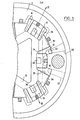
- the valve stator is made up by an assembly of three discoidal pieces 1 , 2 and 3, which are rigidly fixed by means of longitudinal fixing means 4, and are provided with sealing means 5 in order that they can be fitted inside an operating housing, shown by means of wall 6, and which may for example be the steering box of a motor vehicle provided with an hydraulic servo-mechanism.
- the pieces 1 and 3 have wide coaxial passages 7 in order to allow the operating. body for rotor 8 to pass through which may, for example, be the operating shaft of the steering box.
- the rotor 8 is hermetically sealed against the adjacent faces of the pieces 1 and 3, and, using peripheral seals 9, to the internal surfaces of the intermediate piece 2.
- the inner contour of the discoidal intermediate piece 2 has three cylindrical surfaces having a minor radius 10 and three cylindrical surfaces having a major radius 11, which alternate with the former ;
- the rotor 8 has three short arms 12 called “supply arms” because they are facing fluid supply openings, the ends-of which form a hermetic seal with the surfaces of minor radius 10, and three long arms 13 called “discharge arms” because they are facing fluid discharge openings, the ends of which form a seal with the surfaces 11.
- the facing surfaces of the pieces 1 and 3, which make up the axial walls or end walls of the discoidal chamber formed by pieces 1, 2 and 3, are provided with three depressions 14, which are similar in shape to the short arms 12 and are located in a position corresponding to the latter so that the corresponding extreme edges of both are adjacent as can be seen more clearly in Figure 3 and, furthermore, the depressions 14 in the upper piece 1 are extended by means of blind passages 15 which communicate by means of radial conduits 16 with an annular channel 17, which is located between the two upper sealing parts 5 of the valve body. Depressions 14 and supply arms 12 cooperate to define ports having variable cross-section passages 14a called “supply passages" (see Fig. 4).
- depressions 18 which maintain, with respect to arms 13, the same relationships described when reference was made to arms 12 ; the depressions in the lower piece 3 are extended by passages 19 which issue out to the outside of the valve body. Depressions 18 and discharge arms 13 cooperate to define ports having variable cross-section passages 18a called “discharge passages" (see Fig. 4).
- the upper surface 1 has a radial groove 20 which communicates the corresponding enclosure of the valve with the annular channel 21 which is formed between the two intermediate seals 5, and on the other side of each one of the said arms, the lower piece 3 has a radial groove 22 which communicates with an annular channel 23, which is sealed off by the lower sealing parts.
- the arms having differing radii are intended to provide the valve with a reaction effect which is proportional to the effort performed, and the passages 24 are provided for compensating the pressures between the two faces of the arms of the rotor.
- the annular channel 17 is connected, by means of conduits 25, to the fluid pressure source B able to provide for. fluid under pressure ; the channels 21 and 23 connected to the respective chambers of the double-acting actuating cylinder C, using conduits 26, and the passages 19 are connected to the fluid discharge.
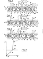
- Tnis operating mode can be represented by line 27 on the graph shown in Figure 7, which shows the fluid pressure P which is present in the respective output conduit 26 as a function of the couple F which is applied to the rotor of the valve, for a determined nominal pressure of the fluid sup- p l y under pressure.
- the slope of line 27 gives an idea of the magnitude of the force which it is necessary to apply to the valve in order to obtain a certain force on the steering mechanism, and this is considered to be adequate for normal running conditions and when performing turns of large radius.
- the inside periphery of the stator or intermediate part 2 is provided with six segments 30 having an identical cylindrical surface which is arranged coaxially with respect to surfaces 10 and 11, each one of the former being arranged between each pair of the latter.
- the rotor in its turn, is provided with six intermedaite arms 31, the ends of which form a hermetic seal, using the respective seals 9, with these surfaces 30, so that the enclosures which, in previous embodiments, were limited by each pair of long and short arms 12 and 13, are now divided into individual pairs of cavities 32 and 33, the first of which, the pressure cavity 32 for providing pressure to one chamber of the cylinder C, is adjacent to the short arm 12 and is-adapted to communicate with the fluid supply through passages 14a, and the second of which, the discharge cavity 33 for providing modulation is adjacent to the long arm 13 and is adapted to be connected to a free discharge of fluid by means of passages18a.
- grooves 20 and 22 which are connected by means of channels 21 and 23 and conduits 26 to the respective chambers of the operating cylinder C, are located in a position adjacent to the rest position of each short arm 12 and are opening u p into pressure cavities 32 on both sides of said short arm.
- one or both facing surfaces of the two parts 1 and 3 which constitute part of the valve body are provided with six depressions 34 which in the rest position of the valve are located so as to face the respective intermediate arms 31 and to define therewith intermediate ports provided with variable cross-section passages 34a (see Fig. 4).
- the arrangement of the whole assembly will be better understood from the diagrams showing the various stages of operation of the valve, shown in Figures 4 to 6.
- the intermediate ports thus connect cavities 32, 33.
- the supply passages 14a are defined by the cooperation of edges of depressions 14 and chamfer means 36 on arms 12
- the discharge passages 18a are defined by the cooperation of edges of depressions 18 and chamfer means 38
- the variable cross-section passages 34a are defined by the cooperation of edges of depressions 34 and chamfer means 37.
- Figure 4 represents the rest position of the valve corresponding tc the origin 35 of the graph shown in Figure 7. It will first of all be noticed that the arrangement of parts 13, 31 is symmetrical on both sides of one particular short arm 12, and it will be clear that fluid under pressure which arrives from the pump B at depressions 14 will become equally distributed at both sides of the said short arm in its rest position and will pass to the discharge 19 whilst passing through the valve devices constituted by the arms 31 and 13 and their respective passages (34a, 18a), so that the two pressure chambers 32 on both sides of each short arm 12 are subject to the same fluid pressure and the operating cylinder C remains in its central rest position, shown in Figure 4.
- the chamfers means 36 and 38 of the short and long arms 12 and 13 are shaped in the usual manner so as to provide the relationship shown by the line 27 in Figure 7, and the chamfer means 37 of the intermediate arm 31 is located so that it is at a position corresponding to a less advanced stage in the operating process, based on the sense of operation ( Figure 4), with respect to the chamfer means 38 of the long arm 13 ; furthermore, this chamfer 37 is shaped so as to provide the relationship indicated by the line 28 in Figure 7.
- the cross-section of passages 34a is equal to or greater than the cross-section of discharge passages 18a up to a determined angular position (illustrated by Figure 5) between rotor and stator from said rest position and decreases more than the cross-section of said discharge passages for a further relative rotation (see Figure 6) from this determined angular position.
- spacing in fact designates the distance between projections of said edges on a common radial plane of the valve (as illustrated by Figure 4) and not the distance between said edges which is not zero for passages 18a on Figure 4.
- Point 29 in the relationship of F/P is reached when the chamfer means 37 starts to block off the passage of fluid, and from this point on, the rotating couple applied to the rotor of the valve continues to increase, the flow of oil is checked by chamfer 37 and the pressure in pressure chamber 32 increases more rapidly, in accordance with the characteristics described by line 28, until point 39 is reached, which corresponds to the nominal pressure for supply of the system ; cylinder C, which is connected to the said chamber 33, is now behaving in accordance with the characteristics represented by line 28.
- the chamfer means 37 is comprised of substantially a single bevelled surface (in embodiment of' Figures 4-6) whereas the chamfer means 38 of the discharge arm 13 comprise a bevelled portion 38a and a portion 38b parallel to theend walls of the discoidal chamber forming the housing of the rotor 8.
- the cross-section of passage 18a remain substantially constant so that the pressure in cavity 33 remains substantially constant whereas the pressure in cavity 32 is still growing thus providing for the characteristics of operation described by line 28 .
- FIG. 8-12 another embodiment is shown with improved chamfer means.
- the chamfer means 37 of the intermediate arm 31 comprises a bevelled portion 37a and a portion 37b substantially parallel to the end walls of the discoidal chamber forming the housing of the rotor 8
- the chamfer means 38 of the discharge means 13 comprise two bevelled portions 38a, 38c separated by a portion 38b substantially parallel to said end walls.
- the pressure growing is one more time controlled by reducing the cross-section of passage 18a so that pressure grows in cavity 33 as well as the reaction couple created in this cavity.
- the result is a loss of the slope of the curve of Figure 11 between points 39a, 39b, the latter corresponding to the maximum pressure Pmax.
- This portion (line 40) in the pressure/couple characteristics has two advantages. Firstly, it provides for an increasing of reaction cf the driving wheel (in case of a power sterring system) warning the driver that the system approaches of its extreme operation conditions. Secondly the operation of the valve in this zone of extreme operation conditions is highly improved because the above improvement in chamfer means eliminates the risk of operation instability.
- the number of sets of arms 12, 31 and 13 can be varied depending on the requirements of each particular application. When it is necessary to operate single-acting devices, it is possible to discard one of the symmetrical halves of the unit described. Alternatively, if it is technically possible, it is possible to provide more than one intermediate arm 31 between each two short and long arms 12 and 13 together with the respective intermediate depressions, and to dimension the various pairs of bevelled edges or chamfers providing closing , in order to obtain operating relationships which are additional to those shown in the graph by lines 27 and 28. Also, it is possible to provide pressure arms 13 and intermediate arms 31 with equal radial lengths thus eliminating hydraulic reaction in pressure cavities 32 which provide for a very important assistance of the power steering for parking manoeuvres (line 28 is substantially vertical).
Landscapes
- Engineering & Computer Science (AREA)
- Chemical & Material Sciences (AREA)
- Combustion & Propulsion (AREA)
- Transportation (AREA)
- Mechanical Engineering (AREA)
- Multiple-Way Valves (AREA)
- Power Steering Mechanism (AREA)
Applications Claiming Priority (3)
| Application Number | Priority Date | Filing Date | Title |
|---|---|---|---|
| ES482107A ES482107A1 (es) | 1979-07-02 | 1979-07-02 | Perfeccionamientos en valvulas de mando de dispositivos accionadores fluidodinamicos. |
| ES482107 | 1979-07-02 | ||
| US06/162,214 US4310024A (en) | 1979-07-02 | 1980-06-23 | Control valve for fluid actuated device |
Publications (2)
| Publication Number | Publication Date |
|---|---|
| EP0021970A1 true EP0021970A1 (de) | 1981-01-07 |
| EP0021970B1 EP0021970B1 (de) | 1983-11-23 |
Family
ID=26155986
Family Applications (1)
| Application Number | Title | Priority Date | Filing Date |
|---|---|---|---|
| EP19800400868 Expired EP0021970B1 (de) | 1979-07-02 | 1980-06-13 | Steuerventil für ein durch Druckmittel betätigtes System |
Country Status (4)
| Country | Link |
|---|---|
| US (1) | US4310024A (de) |
| EP (1) | EP0021970B1 (de) |
| JP (1) | JPS568756A (de) |
| AU (1) | AU533065B2 (de) |
Cited By (10)
| Publication number | Priority date | Publication date | Assignee | Title |
|---|---|---|---|---|
| FR2509006A1 (fr) * | 1981-07-02 | 1983-01-07 | Danfoss As | Mecanisme de commande hydraulique comportant un etranglement reglable |
| FR2514457A1 (fr) * | 1981-07-02 | 1983-04-15 | Danfoss As | Mecanisme de commande hydraulique |
| FR2527732A1 (fr) * | 1982-05-26 | 1983-12-02 | Bendiberica Sa | Distributeur hydraulique rotatif et procede de fabrication de bords de fermeture chanfreines d'organe rotatif d'un tel distributeur |
| EP0066507A3 (en) * | 1981-05-26 | 1984-02-22 | Bendiberica S.A. | Rotative hydraulic distributor for a hydraulic actuating system |
| EP0072731A3 (en) * | 1981-08-04 | 1984-03-28 | Bendiberica S.A. | Hydraulic distributor with reaction on the control organ |
| EP0123619A3 (en) * | 1983-04-26 | 1985-10-02 | Bendiberica S.A. | Hydraulic rotatory distributor, particularly for a vehicle's servo steering system |
| WO1986005753A1 (fr) * | 1985-04-06 | 1986-10-09 | Zahnradfabrik Friedrichshafen Ag | Vanne rotative a tiroir pour direction hydraulique assistee |
| EP0255487A3 (en) * | 1986-08-01 | 1988-09-07 | Carlo Petralli | Physiotherapeutic electronic device to recover the limbs and to restore the skeleton and muscular functions |
| WO1996025318A1 (de) * | 1995-02-17 | 1996-08-22 | Trw Fahrwerksysteme Gmbh & Co. Kg | Drehschieber-lenkventil |
| US5950518A (en) * | 1995-05-20 | 1999-09-14 | Trw Fahrwerksysteme Gmbh & Co. Kg | Rotary disk steering valve |
Families Citing this family (10)
| Publication number | Priority date | Publication date | Assignee | Title |
|---|---|---|---|---|
| US4421191A (en) * | 1980-09-30 | 1983-12-20 | Valeo Societe Anonyme | Power assisted steering device for a vehicle |
| ES8205163A1 (es) * | 1981-08-04 | 1982-06-16 | Bendiberica Sa | Perfeccionamientos en distribuidores fluidodinamicos |
| ES506793A0 (es) * | 1981-10-14 | 1982-08-16 | Bendiberica Sa | Perfeccionamientos en distribuidores hidraulicos rotativos. |
| JPS5958278A (ja) * | 1982-09-28 | 1984-04-03 | Toyoda Mach Works Ltd | ロ−タリバルブ |
| ES518114A0 (es) * | 1982-12-11 | 1983-11-16 | Bendiberica Sa | Perfeccionamientos en sistemas de mando hidraulico para servomecanismos. |
| JPS6015265A (ja) * | 1983-07-04 | 1985-01-25 | Toyoda Mach Works Ltd | サ−ボバルブ |
| ES8605732A1 (es) * | 1984-10-29 | 1986-04-01 | Bendiberica Sa | Perfeccionamientos en distribuidores hidraulicos rotativos, especialmente para sistemas de direccion asistida de vehiculos automoviles |
| US4922803A (en) * | 1989-03-17 | 1990-05-08 | Techco Corporation | Four-way valve |
| US5249503A (en) * | 1990-01-05 | 1993-10-05 | William J. Weinstock | Variable ratio reaction valve |
| JP4727713B2 (ja) * | 2008-12-05 | 2011-07-20 | マックストン株式会社 | 床形成用複合ゴムチップマット |
Citations (3)
| Publication number | Priority date | Publication date | Assignee | Title |
|---|---|---|---|---|
| DE1480666A1 (de) * | 1960-10-14 | 1969-06-19 | Zahnradfabrik Friedrichshafen | Steuerorgan fuer Hydrolenkungen,insbesondere fuer Kraftfahrzeuge |
| DE2009891A1 (de) * | 1969-02-26 | 1970-09-03 | Bishop, Arthur Ernest, Barrington, 111. (V.St.A.) | Steuerschieber für eine Servolenkung insbesondere für Kraftfahrzeuge und Verfahren zur Herstellung solcher Schieber |
| FR2372065A1 (de) * | 1976-11-29 | 1978-06-23 | Bendiberica Sa |
Family Cites Families (2)
| Publication number | Priority date | Publication date | Assignee | Title |
|---|---|---|---|---|
| ES459710A1 (es) * | 1977-06-11 | 1978-04-01 | Bendiberica Sa | Perfeccionamientos en valvulas de mando para servodireccio- nes de vehiculos. |
| GB2051716B (en) * | 1977-07-29 | 1982-05-19 | Honda Motor Co Ltd | Power steering systems |
-
1980
- 1980-06-13 EP EP19800400868 patent/EP0021970B1/de not_active Expired
- 1980-06-23 US US06/162,214 patent/US4310024A/en not_active Expired - Lifetime
- 1980-06-26 AU AU59649/80A patent/AU533065B2/en not_active Ceased
- 1980-07-02 JP JP8926180A patent/JPS568756A/ja active Granted
Patent Citations (3)
| Publication number | Priority date | Publication date | Assignee | Title |
|---|---|---|---|---|
| DE1480666A1 (de) * | 1960-10-14 | 1969-06-19 | Zahnradfabrik Friedrichshafen | Steuerorgan fuer Hydrolenkungen,insbesondere fuer Kraftfahrzeuge |
| DE2009891A1 (de) * | 1969-02-26 | 1970-09-03 | Bishop, Arthur Ernest, Barrington, 111. (V.St.A.) | Steuerschieber für eine Servolenkung insbesondere für Kraftfahrzeuge und Verfahren zur Herstellung solcher Schieber |
| FR2372065A1 (de) * | 1976-11-29 | 1978-06-23 | Bendiberica Sa |
Cited By (13)
| Publication number | Priority date | Publication date | Assignee | Title |
|---|---|---|---|---|
| US4461321A (en) * | 1981-05-26 | 1984-07-24 | Bendiberica S.A. | Rotary hydraulic distributor for hydraulic power-drive systems |
| EP0066507A3 (en) * | 1981-05-26 | 1984-02-22 | Bendiberica S.A. | Rotative hydraulic distributor for a hydraulic actuating system |
| FR2514457A1 (fr) * | 1981-07-02 | 1983-04-15 | Danfoss As | Mecanisme de commande hydraulique |
| FR2509006A1 (fr) * | 1981-07-02 | 1983-01-07 | Danfoss As | Mecanisme de commande hydraulique comportant un etranglement reglable |
| EP0072731A3 (en) * | 1981-08-04 | 1984-03-28 | Bendiberica S.A. | Hydraulic distributor with reaction on the control organ |
| EP0095965A1 (de) * | 1982-05-26 | 1983-12-07 | Bendiberica S.A. | Rotationshydraulischer Verteiler und Herstellungsprozess für Schliessschrägkante des Rotationsteils eines solchen Verteilers |
| FR2527732A1 (fr) * | 1982-05-26 | 1983-12-02 | Bendiberica Sa | Distributeur hydraulique rotatif et procede de fabrication de bords de fermeture chanfreines d'organe rotatif d'un tel distributeur |
| US4540024A (en) * | 1982-05-26 | 1985-09-10 | Bendiberica, S.A. | Rotating hydraulic distributor and method of manufacturing chamfered closing edges of a rotating member of such a distributor |
| EP0123619A3 (en) * | 1983-04-26 | 1985-10-02 | Bendiberica S.A. | Hydraulic rotatory distributor, particularly for a vehicle's servo steering system |
| WO1986005753A1 (fr) * | 1985-04-06 | 1986-10-09 | Zahnradfabrik Friedrichshafen Ag | Vanne rotative a tiroir pour direction hydraulique assistee |
| EP0255487A3 (en) * | 1986-08-01 | 1988-09-07 | Carlo Petralli | Physiotherapeutic electronic device to recover the limbs and to restore the skeleton and muscular functions |
| WO1996025318A1 (de) * | 1995-02-17 | 1996-08-22 | Trw Fahrwerksysteme Gmbh & Co. Kg | Drehschieber-lenkventil |
| US5950518A (en) * | 1995-05-20 | 1999-09-14 | Trw Fahrwerksysteme Gmbh & Co. Kg | Rotary disk steering valve |
Also Published As
| Publication number | Publication date |
|---|---|
| JPS6310034B2 (de) | 1988-03-03 |
| AU533065B2 (en) | 1983-10-27 |
| US4310024A (en) | 1982-01-12 |
| JPS568756A (en) | 1981-01-29 |
| EP0021970B1 (de) | 1983-11-23 |
| AU5964980A (en) | 1981-01-15 |
Similar Documents
| Publication | Publication Date | Title |
|---|---|---|
| EP0021970A1 (de) | Steuerventil für ein durch Druckmittel betätigtes System | |
| US4042310A (en) | Screw compressor control means | |
| SU973010A3 (ru) | Распределитель рулевого управлени транспортного средства | |
| US4217932A (en) | Hydraulic rotary distributor, particularly for use in power steering mechanisms | |
| US4461321A (en) | Rotary hydraulic distributor for hydraulic power-drive systems | |
| US4565115A (en) | Hydraulic distributor for assistance power motor with return to rest position | |
| US4194600A (en) | Hydrodynamic double brake | |
| US4123965A (en) | Rack and pinion power steering gear | |
| US4300594A (en) | Hydraulic rotary distributor, particularly for power steering mechanisms | |
| US4285366A (en) | Pressure medium control system for auxiliary power steering systems | |
| US5868216A (en) | Hydraulic rack-and-pinion steering assembly | |
| US4371002A (en) | Hydrostatic steering system | |
| SU984415A3 (ru) | Гидравлический сервомеханизм вращательного типа | |
| US6000431A (en) | Servo valve | |
| US4465099A (en) | Distribution apparatus, especially for assisted steering system | |
| US2302966A (en) | Pump | |
| US4544131A (en) | Rotary valve | |
| US4222715A (en) | Device for delivery control in a rotary piston compressor | |
| US5218990A (en) | Multiway valve with piston slide valve | |
| US4665797A (en) | Hydraulic distributor for a servomechanism with reaction on the input component | |
| US4438679A (en) | Axial thrust compensating means for power steering control valve | |
| US2773486A (en) | Valve means for a fluid pressure system | |
| SU1090269A3 (ru) | Поворотный золотниковый гидрораспределитель | |
| US3213759A (en) | Hydraulic power unit | |
| GB1071621A (en) | Rotary hydraulic actuators and hydraulically actuated valves |
Legal Events
| Date | Code | Title | Description |
|---|---|---|---|
| PUAI | Public reference made under article 153(3) epc to a published international application that has entered the european phase |
Free format text: ORIGINAL CODE: 0009012 |
|
| 17P | Request for examination filed |
Effective date: 19800715 |
|
| AK | Designated contracting states |
Designated state(s): DE FR GB IT SE |
|
| ITF | It: translation for a ep patent filed | ||
| GRAA | (expected) grant |
Free format text: ORIGINAL CODE: 0009210 |
|
| AK | Designated contracting states |
Designated state(s): DE FR GB IT SE |
|
| REF | Corresponds to: |
Ref document number: 3065674 Country of ref document: DE Date of ref document: 19831229 |
|
| ET | Fr: translation filed | ||
| PLBE | No opposition filed within time limit |
Free format text: ORIGINAL CODE: 0009261 |
|
| STAA | Information on the status of an ep patent application or granted ep patent |
Free format text: STATUS: NO OPPOSITION FILED WITHIN TIME LIMIT |
|
| 26N | No opposition filed | ||
| ITTA | It: last paid annual fee | ||
| EAL | Se: european patent in force in sweden |
Ref document number: 80400868.8 |
|
| PGFP | Annual fee paid to national office [announced via postgrant information from national office to epo] |
Ref country code: SE Payment date: 19960528 Year of fee payment: 17 |
|
| PGFP | Annual fee paid to national office [announced via postgrant information from national office to epo] |
Ref country code: GB Payment date: 19960604 Year of fee payment: 17 |
|
| PGFP | Annual fee paid to national office [announced via postgrant information from national office to epo] |
Ref country code: FR Payment date: 19960607 Year of fee payment: 17 |
|
| PG25 | Lapsed in a contracting state [announced via postgrant information from national office to epo] |
Ref country code: GB Free format text: LAPSE BECAUSE OF NON-PAYMENT OF DUE FEES Effective date: 19970613 |
|
| PG25 | Lapsed in a contracting state [announced via postgrant information from national office to epo] |
Ref country code: SE Effective date: 19970614 |
|
| GBPC | Gb: european patent ceased through non-payment of renewal fee |
Effective date: 19970613 |
|
| PG25 | Lapsed in a contracting state [announced via postgrant information from national office to epo] |
Ref country code: FR Free format text: LAPSE BECAUSE OF NON-PAYMENT OF DUE FEES Effective date: 19980227 |
|
| EUG | Se: european patent has lapsed |
Ref document number: 80400868.8 |
|
| REG | Reference to a national code |
Ref country code: FR Ref legal event code: ST |
|
| REG | Reference to a national code |
Ref country code: FR Ref legal event code: ST |
|
| PGFP | Annual fee paid to national office [announced via postgrant information from national office to epo] |
Ref country code: DE Payment date: 19990624 Year of fee payment: 20 |