EP0021987A1 - Maschine zum unterirdischen Streckenvortrieb - Google Patents
Maschine zum unterirdischen Streckenvortrieb Download PDFInfo
- Publication number
- EP0021987A1 EP0021987A1 EP80400890A EP80400890A EP0021987A1 EP 0021987 A1 EP0021987 A1 EP 0021987A1 EP 80400890 A EP80400890 A EP 80400890A EP 80400890 A EP80400890 A EP 80400890A EP 0021987 A1 EP0021987 A1 EP 0021987A1
- Authority
- EP
- European Patent Office
- Prior art keywords
- frame
- roof
- ground
- advance
- articulation
- Prior art date
- Legal status (The legal status is an assumption and is not a legal conclusion. Google has not performed a legal analysis and makes no representation as to the accuracy of the status listed.)
- Granted
Links
- 238000006073 displacement reaction Methods 0.000 claims description 7
- 230000010355 oscillation Effects 0.000 claims description 5
- 125000006850 spacer group Chemical group 0.000 claims description 5
- 238000012544 monitoring process Methods 0.000 claims 1
- 238000005520 cutting process Methods 0.000 abstract description 24
- 238000003307 slaughter Methods 0.000 description 9
- 239000000725 suspension Substances 0.000 description 5
- 238000009412 basement excavation Methods 0.000 description 3
- 230000000284 resting effect Effects 0.000 description 3
- 238000006243 chemical reaction Methods 0.000 description 2
- 230000000694 effects Effects 0.000 description 2
- 210000001061 forehead Anatomy 0.000 description 2
- 206010012411 Derailment Diseases 0.000 description 1
- 241001669679 Eleotris Species 0.000 description 1
- 230000000295 complement effect Effects 0.000 description 1
- 238000007596 consolidation process Methods 0.000 description 1
- 238000010276 construction Methods 0.000 description 1
- 230000005484 gravity Effects 0.000 description 1
- 235000000396 iron Nutrition 0.000 description 1
- 238000004519 manufacturing process Methods 0.000 description 1
- 239000002184 metal Substances 0.000 description 1
- 238000000034 method Methods 0.000 description 1
- 239000000203 mixture Substances 0.000 description 1
- 238000000465 moulding Methods 0.000 description 1
- 210000000056 organ Anatomy 0.000 description 1
- 230000002250 progressing effect Effects 0.000 description 1
- 239000002689 soil Substances 0.000 description 1
- 239000007787 solid Substances 0.000 description 1
- 238000010408 sweeping Methods 0.000 description 1
Images


Classifications
-
- E—FIXED CONSTRUCTIONS
- E21—EARTH OR ROCK DRILLING; MINING
- E21D—SHAFTS; TUNNELS; GALLERIES; LARGE UNDERGROUND CHAMBERS
- E21D9/00—Tunnels or galleries, with or without linings; Methods or apparatus for making thereof; Layout of tunnels or galleries
- E21D9/10—Making by using boring or cutting machines
- E21D9/1006—Making by using boring or cutting machines with rotary cutting tools
- E21D9/1013—Making by using boring or cutting machines with rotary cutting tools on a tool-carrier supported by a movable boom
- E21D9/102—Making by using boring or cutting machines with rotary cutting tools on a tool-carrier supported by a movable boom by a longitudinally extending boom being pivotable about a vertical and a transverse axis
-
- E—FIXED CONSTRUCTIONS
- E21—EARTH OR ROCK DRILLING; MINING
- E21C—MINING OR QUARRYING
- E21C27/00—Machines which completely free the mineral from the seam
- E21C27/20—Mineral freed by means not involving slitting
- E21C27/22—Mineral freed by means not involving slitting by rotary drills with breaking-down means, e.g. wedge-shaped drills, i.e. the rotary axis of the tool carrier being substantially perpendicular to the working face, e.g. MARIETTA-type
-
- E—FIXED CONSTRUCTIONS
- E21—EARTH OR ROCK DRILLING; MINING
- E21C—MINING OR QUARRYING
- E21C29/00—Propulsion of machines for slitting or completely freeing the mineral from the seam
- E21C29/22—Propulsion of machines for slitting or completely freeing the mineral from the seam by wheels, endless tracks or the like
- E21C29/24—Trucks carrying the machine while working
-
- E—FIXED CONSTRUCTIONS
- E21—EARTH OR ROCK DRILLING; MINING
- E21D—SHAFTS; TUNNELS; GALLERIES; LARGE UNDERGROUND CHAMBERS
- E21D9/00—Tunnels or galleries, with or without linings; Methods or apparatus for making thereof; Layout of tunnels or galleries
- E21D9/10—Making by using boring or cutting machines
- E21D9/1006—Making by using boring or cutting machines with rotary cutting tools
- E21D9/1013—Making by using boring or cutting machines with rotary cutting tools on a tool-carrier supported by a movable boom
- E21D9/102—Making by using boring or cutting machines with rotary cutting tools on a tool-carrier supported by a movable boom by a longitudinally extending boom being pivotable about a vertical and a transverse axis
- E21D9/1026—Making by using boring or cutting machines with rotary cutting tools on a tool-carrier supported by a movable boom by a longitudinally extending boom being pivotable about a vertical and a transverse axis the tool-carrier being rotated about a transverse axis
-
- E—FIXED CONSTRUCTIONS
- E21—EARTH OR ROCK DRILLING; MINING
- E21D—SHAFTS; TUNNELS; GALLERIES; LARGE UNDERGROUND CHAMBERS
- E21D9/00—Tunnels or galleries, with or without linings; Methods or apparatus for making thereof; Layout of tunnels or galleries
- E21D9/10—Making by using boring or cutting machines
- E21D9/1093—Devices for supporting, advancing or orientating the machine or the tool-carrier
Definitions
- the present invention relates to a system for digging underground galleries, in particular mine galleries.
- the digging of the underground galleries involves three distinct operations which, in a conventional manner, are carried out successively, namely the felling, the removal of the cuttings and the support.
- slaughter was mechanized by the use of slaughter tools mounted on a chain or on a drum and associated with a frame capable of advancing continuously. It is also known to mechanize the removal of cuttings by mechanical scraper arms which drive them towards a conveyor belt.
- the stability of the assembly against reaction forces exerted on the slaughtering tool is essentially ensured by the weight of the frame.
- this frame is generally of moderate height and the tool is articulated on it at a relatively low point, so that the reaction forces tend to tilt the assembly.
- the stability of the assembly is therefore precarious, and in particular means that the installed power must be limited.
- there is only a small clearance between the ground and the machine so that it is difficult to introduce a member there independent of excavation of cuttings. This member is then incorporated into the machine and prevents any access to the cutting face.
- the present invention aims to provide a digging system which allows the roof to be supported without interrupting the felling operation, which offers total stability, which makes it possible to significantly increase the power installed for felling, and which offers a large clearance above the ground to conveniently install an independent cuttings evacuation device, allowing easy access to the cutting face.
- the system for digging underground galleries comprises a felling tool articulated on a frame, and mounted so as to be able to be moved along the height of the working face.
- This frame is provided with support means on the ground and propulsion means to follow the advance of the felling, and the system is characterized in that the point of articulation of the felling tool is located in the upper half of the system in operating position.
- This arrangement makes it possible to reserve a very large free space under the machine. This also results in a stroke of the felling tool such that the working face has a slope closer to that of the natural slope, which reduces the risk of landslides.
- the point of articulation of the felling tool is located on a movable member relative to the frame and capable of being moved in a direction substantially parallel to the direction of advance.
- the actual slaughter phase corres laying on the tool stroke, is preceded by a tool advance phase in the cutting face. Thanks to the aforementioned arrangement, this advance is effected not by an advance of the frame, but by the movable member, the frame remaining firmly in contact with the ground and the roof. Stability is thus better ensured during this phase.
- the shaft carrying the felling tool is mounted on two bearings, one of which is movable vertically to give the tool an oblique stroke in a predetermined direction.
- the frame is provided with at least one mobile support device on the roof of the gallery allowing the advance of the frame during the digging operation.
- This arrangement has the double advantage of providing under the roof of the gallery a support advancing with the entire system as the felling, and, in cooperation with the support means on the ground, to achieve a real embedding of the system in the gallery, protecting it from any tilting.
- each support device on the roof is articulated on the frame by means of two substantially rectangular axes of rotation, so as to accommodate misalignments of the roof.
- each roof support device is advantageously connected to a jack.
- each roof support device comprises a crawler train which bears against the roof.
- Each tracked train comprises at least one track cooperating with a guide track connected to a frame by means of a double articulation with two substantially rectangular axes of oscillation, making it possible to compensate for the unevenness of the roof surface.
- the ground support means comprise two caterpillar tracks arranged laterally.
- the propulsion means comprise a linear displacement motor member, a fixed part of which is connected to the frame, and a movable part of which cooperates with a rack formed in the track supporting the ground, the stroke of this member corresponding to a step in the advance of the slaughter tool.
- the crawler trains for supporting the ground preferably comprise each at least one track cooperating with a guide track connected to the frame by a double articulation with two axes. of substantially rectangular oscillations, to make up for unevenness in the ground.
- one of the crawler tracks on the ground is connected to the frame by an articulation with a substantially horizontal axis and perpendicular to the direction of advance.
- the frame comprises a flat spacer located at the level of the tracked support train on the ground and provided with liftable inclined planes to facilitate crossing.
- the system is thus provided with an upper spacer and a lower spacer, which improves its rigidity.
- the embodiment indicated does not obstruct access to the cutting face or the passage of excavation equipment.
- the roof support device comprises at least one sliding member articulated on the frame provided with pads to cooperate with beams held applied to the roof by said member.
- These beams act as a sliding path for the frame and at the same time support the roof immediately behind the cutting face.
- the sliding molding then advantageously comprises retractable feet for bearing on the roof and releasing the beams in order to make them advance at each advance step of the digging.
- the frame includes pads sliding to cooperate with support beams placed laterally on the ground.
- the progression means comprise a linear displacement motor member of which a fixed part is connected to the frame, and of which a movable part is connected to a support beam.
- the frame includes retractable feet for coming to bear on the ground and clearing the support beams, in order to make them advance at each advance step of digging.
- the invention provides that the roof support devices are arranged obliquely to take support on the roof of such a gallery.
- the slaughtering tool then comprises a truncated cone provided with tools mounted at the end of a shaft connected to the chassis by an articulation allowing angular displacements of the arm in two substantially perpendicular planes.
- composition of these two displacements makes it possible to carry out the curvilinear displacements corresponding to the profile of the gallery.
- the articulation of the arm on the frame is slidably mounted on a substantially horizontal crosspiece of the frame.
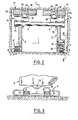
- the digging system comprises a frame 1 composed of two lateral flanges 2, 3 connected together by shafts 4, 5 and each resting on a crawler train, respectively 6, 7.
- the flange 2 is connected to the train 6 by means of two suspension devices 8 each composed, in a manner known per se, of two cylindrical grains stepped and perpendicular to each other, cooperating with complementary female bearing surfaces ( Figures 1 and 2), so as to provide two degrees of freedom between the flange 2 and the guide 9 of the tracks 11.
- the flange 3 is connected to the train 7 in substantially the same way, but, in addition, a frame 12 which carries the suspension devices 8 is articulated on the flange 3 via a shaft 13 substantially horizontal ( Figures 2 and 3), so that the train 7 as a whole can oscillate in a plane vertical parallel to the direction of advance of the system. It is thus possible to obtain good simultaneous seating of the two trains 6 and 7, even if the ground has a left surface.
- Two arms 14 are each articulated, on the one hand, on the shaft 4 by means of a yoke 15 and, on the other hand, on a member 16 of a crawler train 17 by means of a yoke 18.
- Cylinders 19, whose body 21 takes a ball joint in the thickness of the flanges 2 and 3, and whose rod 22 also takes a ball joint in a cavity 23 of each arm 14, are arranged so as to push up the arms 14 to apply the trains 17 on the roof of the gallery.
- Each of the trains 17 comprises a chassis 24 articulated on the frame 16 by pins 25 whose axis is substantially parallel to the direction of advance of the system.
- Each of the chassis 24 carries two tracks 26 by means of suspension devices 8 with two rectangular oscillation axes (FIG. 4) and guides 27.
- the tracks 26 are provided wide enough to cover a large part of the roof and provide effective support.
- the shaft 5 which is located, like the shaft 4, in the upper half of the assembly, carries two rotary arms 28 which serve by bearing, by their other end, to the shaft 29 of a drum slaughter 31, and are joined by a cross member 32.
- the drum 31 consists, in particular, of a helical sheet 33, fixed on a rotary sleeve 34 integral with the shaft 29, and which carries, on its edge, cutting tools 35 ( Figures 5 and 6).
- the propeller has steps in opposite directions on each side of the drum so as, in cooperation with the direction of rotation of the drum, to bring the cuttings towards the median longitudinal plane of the system.
- each arm 28 On each arm 28 is fixed a geared motor group 36 which, by means of a train with three pinions, 37, 38, 39, attacks the shaft 29.
- the sheet metal 33 in helix is interrupted and replaced by a felling chain 41, also provided with cutting tools 35, and resting on a casing 42 enveloping the three pinions.
- Two drive nuts 43, 44 are integral with the sleeve 34 and mesh with the chain 41.
- Each arm 28 is connected by an articulation 45 to the rod of a jack 46 articulated on the other hand on a yoke 47 secured to the corresponding flange of the frame 1.
- a jack 48 is articulated on one of the suspension devices 8, and its rod carries a fault 49 capable of coming to engage by gravity in notches 51 made each in a link of the track 11 ( Figure 7).
- the actuation of the jack thus allows the progression of the system via the tracks.
- the felling drum is brought into the upper position 31a (FIG. 1) by means of the jacks 46, and it is made to rotate by means of the geared motors groups 36.
- the jacks 19 being actuated so as to apply the upper gears 17 to the roof, the entire system is brought forward by means of the jacks 48. During this advance, the drum 31 digs the ground and we stops the advance when it reaches 31b.
- the cylinder 46 is retracted, which lowers the drum 31 which envelops the surface S shown in phantom, and stops the downward movement when the drum has reached ground level.
- the tracks are applied exactly on the ground and on the roof, even in the event of a flatness or irregularity. Thanks to the articulation 13 of the frame 12, the lower tracks are, in fact, not subject to remaining in the same plane.
- the articulated fixing of the top crawler trains around the pins 25, allows these trains to match the irregularities of the roof. Finally, the suspension devices 8 with two articulation axes allow each track to match small roughness independently.
- the upper tracks widely applied on the roof provide sufficient temporary support which can be made final by a comfortable working team immediately behind the system and intervening as soon as a new advance has cleared an additional part of the roof.
- the way in which the system is embedded between the ground and the roof makes it possible, without loss of stability, to place the shaft 5 in a relatively high position, so that the sweeping of the drum 31 leaves a front of size S relatively close to the natural slope, or at least looking generally upwards, which is an arrangement going against the collapses of the forehead.
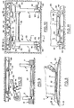
- the flanges 2 and 3 of the frame 1 are joined rigid ment by a flat spacer 52 located near the ground level ( Figures 8 and 9).
- Articulated drawbridges 53 liftable by jacks (not shown), can rest on the ground to allow easy passage of personnel and loads.
- a frame 101 consists of two lateral flanges 102, 103, interconnected by a shaft 104 and by a shaft 105, not shown, similar to the shaft 5 of the previous embodiment and playing the same role.
- the flanges 102, 103 carry sliding shoes 161 provided to cooperate with profiled irons 162 arranged on the ground in the direction of advance of the system, to constitute support beams. Hooks 163 are provided to prevent derailments.
- two retractable feet 164 controlled by jacks 165 allow the frame 101 to rest on the ground to relieve the profiles 162.
- Two arms 114 are articulated by yokes 115 on the shaft 105 and each carry, by a yoke 118, at their other end, a sliding member 116.
- the arms 114 are actuated by jacks 119, as in the previous embodiment, to allow apply the pads 117 upwards.
- Each of the pads 117 carries two retractable feet 167 actuated by jacks to bear on the roof and allow the sections 166 to be relieved.
- a jack 148 has its body articulated on the flange and its rod articulated on a yoke 149 fixed to the corresponding section 162. It is understood that the extension of the jack causes the sliding of the frame on the profiles 162.
- slaughtering means are the same as in the previous embodiment and operate in the same way.
- the actuator 148 is actuated to cause the frame to slide on the profiles 162, over a distance corresponding to a predetermined step of advance.
- the retractable feet 164 and 167 are protruded so that the frame is supported on the ground and on the roof only by these feet, and the actuator is actuated in the other direction to bring the profiles 162.
- the profiles 166 which constitute a movable support, and there is a fixed support behind them.
- FIG. 13 takes up part of FIG. 1 in this other embodiment.
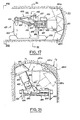
- Two rotary arms 228 carrying a cutting drum 231 are articulated not on the flanges 202, 203 of the frame, but on movable members 268 themselves articulated on the flanges respectively. These organs can be moved in a vertical plane parallel to the direction of advance by respective jacks 269 fixed elsewhere to the flanges.
- the arms 228 are actuated, as in the previous embodiment, by jacks 246.
- the arms 228 and the drum 231 are moved forward at 228b and 231b to a position defining a new size S front 2.
- the drum is then lowered to 231c to achieve the front S 2.
- the drum is brought back to position 231.
- this arrangement has the advantage of advancing the drum from 231a to 231b, while the system is stopped and, therefore, stable and firmly embedded in the gallery. A more regular soil is also produced by leveling off the hatched part A perfectly.
- the shaft 305 carrying the arms 328 of the felling drum is mounted on two bearings, one of which, 371, is slidably mounted on the flange 302 of the frame, the other 372 being fixed.
- the shaft 305 is fixed in rotation, but can pivot around a pin 373 located in bearing 372, so that the shaft can come to occupy an oblique position 305a.
- the bearings 371 and 372 are bi-coniqui is to allow the expected angular movement.
- two jacks 374 have their bodies fixed to the frame 302, while their rods 375 are applied to the bearing 372 ( Figure 15).
- the shaft 305 comes into an oblique position 305a, which makes it possible to lift the felling drum also in the oblique position 331a, to dig an oblique roof.
- This arrangement finds its advantage when one has to dig a gallery in a sloping deposit, the gallery progressing under a bench without cutting it. We can then, while giving the gallery a horizontal floor (or at least without slope), give it a roof consisting of the bench chosen most of the time for its mechanical qualities.
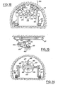
- a frame 401 comprises two flanges 402, 403, mounted on crawler trains 406, 407 respectively, resting on the ground and similar to those of the preceding embodiments.
- a shaft 404 bent in an inverted V is fixed by its respective ends in the flanges 402, 403, and carries on its inclined portions bearings 415 of arms 414 articulated on crawler trains 417, applied to the roof of the gallery.
- crawler trains 417 are similar to trains 17 of the first embodiment described and their method of attachment to the system is similar.
- An arm 483 provides a consolidation link between the arm 404 and the arm 481.
- a horizontal transverse shaft 405 carries a slide 484 ( Figures 17, 20, 21). This slide is fixed to the rod 485 of a jack 486 whose body, parallel to the shaft 405, is fixed to the flange 403, allowing the slide to be moved along the shaft 405.
- a yoke 487 is fixed to the slide 484 by means of two pivots 488 constituting a vertical axis of rotation.
- This yoke carries a geared motor group 489 at the end of the shaft which is wedged a frustoconical felling tool 491.
- a hydraulic motor 492 is fixed on the yoke 487 and actuates a pinion 493 which meshes with a toothed sector 494 secured to the slide 484.
- a jack 495 has its body fixed to the arm 483 by means of a joint, and its rod 496 fixed, also by a joint, to a piece 497 for connection to the yoke 487.
- the movements of the rod of this jack thus make it possible to rotate the slide 484 around the shaft 405. This movement is permitted in any axial position of the slide on the shaft, thanks to the articulated connections of the jack 495.
- the yoke 487 is then made to rotate by means of the hydraulic motor 492 counterclockwise to bring it into position 491, starting the cutting face, according to F1. It is noted that, during this evolution, the tool does not work by its angular edge, but by its lateral surface.
- This operation is repeated at different levels, such as 491e and 491f ( Figure 17), so as to cut the entire front, by operating the jack 489.
- the transverse trees are placed at a fairly high level, normally in the upper half of the gallery, which frees up a large space for the evacuation of spoil.
- the operations of cutting, supporting and removing the cuttings are carried out simultaneously and without interruption.
Landscapes
- Engineering & Computer Science (AREA)
- Mining & Mineral Resources (AREA)
- Geology (AREA)
- Life Sciences & Earth Sciences (AREA)
- General Life Sciences & Earth Sciences (AREA)
- Geochemistry & Mineralogy (AREA)
- Environmental & Geological Engineering (AREA)
- Mechanical Engineering (AREA)
- Shovels (AREA)
- Excavating Of Shafts Or Tunnels (AREA)
- Earth Drilling (AREA)
- Steroid Compounds (AREA)
- Control Of Electric Motors In General (AREA)
- Separation By Low-Temperature Treatments (AREA)
Priority Applications (1)
| Application Number | Priority Date | Filing Date | Title |
|---|---|---|---|
| AT80400890T ATE4135T1 (de) | 1979-06-21 | 1980-06-18 | Maschine zum unterirdischen streckenvortrieb. |
Applications Claiming Priority (2)
| Application Number | Priority Date | Filing Date | Title |
|---|---|---|---|
| FR7915908A FR2459360B1 (fr) | 1979-06-21 | 1979-06-21 | Systeme pour creuser des galeries souterraines |
| FR7915908 | 1979-06-21 |
Publications (2)
| Publication Number | Publication Date |
|---|---|
| EP0021987A1 true EP0021987A1 (de) | 1981-01-07 |
| EP0021987B1 EP0021987B1 (de) | 1983-07-13 |
Family
ID=9226912
Family Applications (1)
| Application Number | Title | Priority Date | Filing Date |
|---|---|---|---|
| EP80400890A Expired EP0021987B1 (de) | 1979-06-21 | 1980-06-18 | Maschine zum unterirdischen Streckenvortrieb |
Country Status (5)
| Country | Link |
|---|---|
| US (1) | US4362337A (de) |
| EP (1) | EP0021987B1 (de) |
| AT (1) | ATE4135T1 (de) |
| DE (1) | DE3064115D1 (de) |
| FR (1) | FR2459360B1 (de) |
Cited By (7)
| Publication number | Priority date | Publication date | Assignee | Title |
|---|---|---|---|---|
| EP0192357A1 (de) * | 1985-02-20 | 1986-08-27 | Dosco Overseas Engineering Limited | Abbaumaschinenpark |
| US4688855A (en) * | 1985-01-29 | 1987-08-25 | Voest-Alpine Aktiengesellschaft | Drift advancing or exploiting machine |
| DE3923376C1 (en) * | 1989-07-14 | 1990-07-05 | Paurat Gmbh, 4223 Voerde, De | Self propelling machine for mining coal - comprises platform supported by vertical hydraulic jacks and raking jacks |
| DE4037620A1 (de) * | 1990-11-27 | 1992-06-04 | Ketterer Klaus | Teilschnittmaschine mit seitlichem raupenfahrwerk |
| WO1997048883A1 (en) * | 1996-06-17 | 1997-12-24 | Joy Mm Delaware, Inc. | Mining machine with multiple propulsion members |
| EP1013875A3 (de) * | 1998-12-21 | 2001-08-16 | Angerlehner Hoch- und Tiefbau GmbH | Einrichtung und Verfahren zum Vergrössern des Querschnitts eines Erdbauwerks |
| CN115163075A (zh) * | 2022-08-18 | 2022-10-11 | 四川发展天瑞矿业有限公司 | 一种中厚缓倾斜磷矿全厚分层采矿方法 |
Families Citing this family (8)
| Publication number | Priority date | Publication date | Assignee | Title |
|---|---|---|---|---|
| GB2212836B (en) * | 1987-11-25 | 1991-12-04 | Anderson Strathclyde Plc | Mining machine |
| AT392512B (de) * | 1989-06-15 | 1991-04-25 | Voest Alpine Maschinenbau | Schraemmaschine |
| US6270163B1 (en) | 1998-09-14 | 2001-08-07 | Holmes Limestone Co. | Mining machine with moveable cutting assembly and method of using the same |
| US6224164B1 (en) | 1999-02-12 | 2001-05-01 | Joy Mm Delaware, Inc. | Mining machine with detachable articulated cutting assembly |
| US7434764B2 (en) * | 2005-12-02 | 2008-10-14 | Sikorsky Aircraft Corporation | Variable speed gearbox with an independently variable speed tail rotor system for a rotary wing aircraft |
| US9631491B2 (en) * | 2007-12-17 | 2017-04-25 | Hilary Leith Lumb | Apparatus for forming an underground tunnel |
| GB201113851D0 (en) * | 2011-08-11 | 2011-09-28 | Thomas Gareth J | Excavator vehicle |
| CN113389564B (zh) * | 2021-06-29 | 2023-09-05 | 中铁建工集团有限公司 | 一种地下隧道施工运料的安全辅助结构 |
Citations (17)
| Publication number | Priority date | Publication date | Assignee | Title |
|---|---|---|---|---|
| FR1118233A (fr) * | 1954-01-25 | 1956-06-01 | Coal Industry Patents Ltd | Haveuse de galerie |
| DE948232C (de) * | 1953-08-08 | 1956-08-30 | Korfmann Gmbh Maschf | Streckenvortriebsmaschine |
| FR1127180A (fr) * | 1954-11-09 | 1956-12-10 | Bade & Co Gmbh | Chariot d'avancement pour machines automotrices d'avancement des galeries |
| GB777393A (en) * | 1954-04-01 | 1957-06-19 | Eickhoff Geb | Improvements relating to mineral mining machines |
| FR1159102A (fr) * | 1955-10-31 | 1958-06-23 | Inst Mechanizacji Gornictwa | Machine combinée pour mines servant à l'exploitation en galeries |
| FR1268468A (fr) * | 1959-11-17 | 1961-08-04 | Lorraine Houilleres | Machine minière d'abattage intégral pour veines en dressants |
| FR1276927A (fr) * | 1960-12-28 | 1961-11-24 | Eickhoff Geb | Machine pour le percement de galeries |
| FR1400211A (fr) * | 1964-07-06 | 1965-05-21 | Salzgitter Maschinen Ag | Haveuse de montages ou de chambres de machines dans les mines de charbon |
| DE2040286A1 (de) * | 1970-08-13 | 1972-02-17 | Konrad Grebe | Streckenvortriebsmaschine |
| FR2207241A1 (de) * | 1972-11-21 | 1974-06-14 | Sp Konstruktors | |
| US3879088A (en) * | 1973-09-13 | 1975-04-22 | Jr George Sodder | Longwall mining system |
| FR2300892A1 (fr) * | 1975-02-14 | 1976-09-10 | Coal Industry Patents Ltd | Machine d'abattage de minerai de mobilite amelioree |
| US4040669A (en) * | 1975-12-11 | 1977-08-09 | Franklin Wesley D | Self propelled excavating vehicle |
| FR2339057A1 (fr) * | 1976-01-26 | 1977-08-19 | Charbonnages De France | Support unitaire de soutenement marchant |
| FR2356809A1 (fr) * | 1976-06-29 | 1978-01-27 | Charbonnages De France | Pile mobile de soutenement continu |
| FR2405421A3 (fr) * | 1977-10-07 | 1979-05-04 | Charbonnages De France | Dispositif d'appui a deux degres de liberte angulaire |
| FR2411299A2 (fr) * | 1977-12-06 | 1979-07-06 | Charbonnages De France | Pile mobile de soutenement continu |
Family Cites Families (7)
| Publication number | Priority date | Publication date | Assignee | Title |
|---|---|---|---|---|
| CA648736A (en) * | 1962-09-18 | Aktiebolaget Bofors | Weapon-carrying vehicles of the endless track type | |
| US1736853A (en) * | 1924-03-08 | 1929-11-26 | Jeffrey Mfg Co | Mining machine |
| GB1111484A (en) * | 1965-12-10 | 1968-04-24 | Greenside Machine Co Ltd | Improvements in or relating to tunnelling machines and methods of tunnelling |
| FR2253143B1 (de) | 1973-11-30 | 1978-11-03 | Alsace Mines Potasse | |
| US3966258A (en) * | 1974-12-16 | 1976-06-29 | Joy Manufacturing Company | Mining boom linkage for separate sump and swing cutting |
| US4040699A (en) * | 1976-10-18 | 1977-08-09 | Crest Industries, Inc. | Female connector and escutcheon plate combined therewith for telephone equipment |
| EP0004832B1 (de) * | 1978-04-04 | 1982-04-14 | Atlas Copco Aktiebolag | Maschine zum Vortreiben von Tunneln und Verfahren zum Vortreiben von Tunneln mit dieser Maschine |
-
1979
- 1979-06-21 FR FR7915908A patent/FR2459360B1/fr not_active Expired
-
1980
- 1980-06-18 AT AT80400890T patent/ATE4135T1/de not_active IP Right Cessation
- 1980-06-18 EP EP80400890A patent/EP0021987B1/de not_active Expired
- 1980-06-18 DE DE8080400890T patent/DE3064115D1/de not_active Expired
- 1980-06-18 US US06/160,459 patent/US4362337A/en not_active Expired - Lifetime
Patent Citations (17)
| Publication number | Priority date | Publication date | Assignee | Title |
|---|---|---|---|---|
| DE948232C (de) * | 1953-08-08 | 1956-08-30 | Korfmann Gmbh Maschf | Streckenvortriebsmaschine |
| FR1118233A (fr) * | 1954-01-25 | 1956-06-01 | Coal Industry Patents Ltd | Haveuse de galerie |
| GB777393A (en) * | 1954-04-01 | 1957-06-19 | Eickhoff Geb | Improvements relating to mineral mining machines |
| FR1127180A (fr) * | 1954-11-09 | 1956-12-10 | Bade & Co Gmbh | Chariot d'avancement pour machines automotrices d'avancement des galeries |
| FR1159102A (fr) * | 1955-10-31 | 1958-06-23 | Inst Mechanizacji Gornictwa | Machine combinée pour mines servant à l'exploitation en galeries |
| FR1268468A (fr) * | 1959-11-17 | 1961-08-04 | Lorraine Houilleres | Machine minière d'abattage intégral pour veines en dressants |
| FR1276927A (fr) * | 1960-12-28 | 1961-11-24 | Eickhoff Geb | Machine pour le percement de galeries |
| FR1400211A (fr) * | 1964-07-06 | 1965-05-21 | Salzgitter Maschinen Ag | Haveuse de montages ou de chambres de machines dans les mines de charbon |
| DE2040286A1 (de) * | 1970-08-13 | 1972-02-17 | Konrad Grebe | Streckenvortriebsmaschine |
| FR2207241A1 (de) * | 1972-11-21 | 1974-06-14 | Sp Konstruktors | |
| US3879088A (en) * | 1973-09-13 | 1975-04-22 | Jr George Sodder | Longwall mining system |
| FR2300892A1 (fr) * | 1975-02-14 | 1976-09-10 | Coal Industry Patents Ltd | Machine d'abattage de minerai de mobilite amelioree |
| US4040669A (en) * | 1975-12-11 | 1977-08-09 | Franklin Wesley D | Self propelled excavating vehicle |
| FR2339057A1 (fr) * | 1976-01-26 | 1977-08-19 | Charbonnages De France | Support unitaire de soutenement marchant |
| FR2356809A1 (fr) * | 1976-06-29 | 1978-01-27 | Charbonnages De France | Pile mobile de soutenement continu |
| FR2405421A3 (fr) * | 1977-10-07 | 1979-05-04 | Charbonnages De France | Dispositif d'appui a deux degres de liberte angulaire |
| FR2411299A2 (fr) * | 1977-12-06 | 1979-07-06 | Charbonnages De France | Pile mobile de soutenement continu |
Cited By (10)
| Publication number | Priority date | Publication date | Assignee | Title |
|---|---|---|---|---|
| US4688855A (en) * | 1985-01-29 | 1987-08-25 | Voest-Alpine Aktiengesellschaft | Drift advancing or exploiting machine |
| AT386051B (de) * | 1985-01-29 | 1988-06-27 | Voest Alpine Ag | Streckenvortriebs- oder gewinnungsmaschine |
| EP0192357A1 (de) * | 1985-02-20 | 1986-08-27 | Dosco Overseas Engineering Limited | Abbaumaschinenpark |
| AU581725B2 (en) * | 1985-02-20 | 1989-03-02 | Dosco Overseas Engineering Ltd | Mining machinery |
| DE3923376C1 (en) * | 1989-07-14 | 1990-07-05 | Paurat Gmbh, 4223 Voerde, De | Self propelling machine for mining coal - comprises platform supported by vertical hydraulic jacks and raking jacks |
| DE4037620A1 (de) * | 1990-11-27 | 1992-06-04 | Ketterer Klaus | Teilschnittmaschine mit seitlichem raupenfahrwerk |
| WO1997048883A1 (en) * | 1996-06-17 | 1997-12-24 | Joy Mm Delaware, Inc. | Mining machine with multiple propulsion members |
| EP1013875A3 (de) * | 1998-12-21 | 2001-08-16 | Angerlehner Hoch- und Tiefbau GmbH | Einrichtung und Verfahren zum Vergrössern des Querschnitts eines Erdbauwerks |
| CN115163075A (zh) * | 2022-08-18 | 2022-10-11 | 四川发展天瑞矿业有限公司 | 一种中厚缓倾斜磷矿全厚分层采矿方法 |
| CN115163075B (zh) * | 2022-08-18 | 2023-10-03 | 四川发展天瑞矿业有限公司 | 一种中厚缓倾斜磷矿全厚分层采矿方法 |
Also Published As
| Publication number | Publication date |
|---|---|
| US4362337A (en) | 1982-12-07 |
| FR2459360A1 (fr) | 1981-01-09 |
| DE3064115D1 (en) | 1983-08-18 |
| ATE4135T1 (de) | 1983-07-15 |
| FR2459360B1 (fr) | 1986-04-18 |
| EP0021987B1 (de) | 1983-07-13 |
Similar Documents
| Publication | Publication Date | Title |
|---|---|---|
| EP0021987A1 (de) | Maschine zum unterirdischen Streckenvortrieb | |
| EP0017593B1 (de) | Gerät zum Ausbaggern von Teichen, Morasten oder Gräben | |
| AU659378B2 (en) | Mobile mining machine having tilted swing axis | |
| EP0095795B2 (de) | Maschine zum unterirdischen Streckenvortrieb | |
| CA3114364A1 (fr) | Equipement de formage de surfaces, procede de fabrication et utilisation de l'equipement de formage de surfaces et unite mobile incluant l'equipement de formage de surfaces | |
| WO2010119186A1 (fr) | L'invention concerne un dispositif multifonction pour terrassement, nivellement et compactage | |
| FR2493370A1 (fr) | Bras articule pour engin d'excavation | |
| EP0300874A1 (de) | Bohrvorrichtung zum Drehen und hin- und hergehenden Drehen | |
| CH622058A5 (en) | Machine for digging galleries or tunnels | |
| CH657649A5 (en) | Railway site machine for the at least partial repair of a railway track portion | |
| FR2480815A1 (fr) | Machine de construction des voies ferrees comprenant un dispositif pour deblayer et aplanir la couche de ballast | |
| EP3241985A1 (de) | Tunnelbohrer | |
| EP0282416B1 (de) | Schrämmaschine mit einem beweglich auf einer gewölbt gebogenen und zu ihrer Achse schrägen Führung montierten Schrämmkopf | |
| FR2504829A1 (fr) | Dispositif de creusement de rigoles de hauts fourneaux et analogues | |
| EP0177388A1 (de) | Grassmaschine für weichen oder unebenen Untergrund, insbesondere zum Reinigen von Teichen, Marschen oder Kanälen | |
| FR2570758A1 (fr) | Machine ponctuelle a dispositif de chargement reglable | |
| FR2539157A1 (fr) | Trancheuse a fleche | |
| FR3050758B1 (fr) | Tunnelier | |
| FR2718169A1 (fr) | Engin de façonnage et/ou de remise en état de bas-côtés. | |
| FR2461806A1 (fr) | Machine de creusement comportant un bras muni d'un outil d'abattage et orientable | |
| FR2555660A1 (fr) | Dispositif pour la mise en place d'elements de soutenements marchants hydrauliques dans une exploitation souterraine, en particulier pour une taille fortement inclinee | |
| EP0603024B1 (de) | Verfahren zur Herstellung von Querdurchgängen unter Eisenbahntrassen | |
| EP0085790B1 (de) | Bauzug zur Erneuerung einer Eisenbahnschienenstrecke | |
| FR3019566B1 (fr) | Machine pour le betonnage en continu de fosses munie d'un treuil | |
| FR3153836A1 (fr) | Systeme de fauchage robotise de la vegetation d’une voie ferroviaire, vehicule d’entretien et procede associe |
Legal Events
| Date | Code | Title | Description |
|---|---|---|---|
| PUAI | Public reference made under article 153(3) epc to a published international application that has entered the european phase |
Free format text: ORIGINAL CODE: 0009012 |
|
| 17P | Request for examination filed |
Effective date: 19800707 |
|
| AK | Designated contracting states |
Designated state(s): AT BE CH DE GB IT LU NL SE |
|
| GRAA | (expected) grant |
Free format text: ORIGINAL CODE: 0009210 |
|
| AK | Designated contracting states |
Designated state(s): AT BE CH DE GB IT LI LU NL SE |
|
| PG25 | Lapsed in a contracting state [announced via postgrant information from national office to epo] |
Ref country code: SE Effective date: 19830713 Ref country code: NL Effective date: 19830713 Ref country code: IT Free format text: LAPSE BECAUSE OF FAILURE TO SUBMIT A TRANSLATION OF THE DESCRIPTION OR TO PAY THE FEE WITHIN THE PRESCRIBED TIME-LIMIT;WARNING: LAPSES OF ITALIAN PATENTS WITH EFFECTIVE DATE BEFORE 2007 MAY HAVE OCCURRED AT ANY TIME BEFORE 2007. THE CORRECT EFFECTIVE DATE MAY BE DIFFERENT FROM THE ONE RECORDED. Effective date: 19830713 |
|
| REF | Corresponds to: |
Ref document number: 4135 Country of ref document: AT Date of ref document: 19830715 Kind code of ref document: T |
|
| PG25 | Lapsed in a contracting state [announced via postgrant information from national office to epo] |
Ref country code: AT Effective date: 19830801 |
|
| REF | Corresponds to: |
Ref document number: 3064115 Country of ref document: DE Date of ref document: 19830818 |
|
| NLV1 | Nl: lapsed or annulled due to failure to fulfill the requirements of art. 29p and 29m of the patents act | ||
| PLBE | No opposition filed within time limit |
Free format text: ORIGINAL CODE: 0009261 |
|
| STAA | Information on the status of an ep patent application or granted ep patent |
Free format text: STATUS: NO OPPOSITION FILED WITHIN TIME LIMIT |
|
| PG25 | Lapsed in a contracting state [announced via postgrant information from national office to epo] |
Ref country code: LU Free format text: LAPSE BECAUSE OF NON-PAYMENT OF DUE FEES Effective date: 19840630 Ref country code: LI Effective date: 19840630 Ref country code: CH Effective date: 19840630 Ref country code: BE Effective date: 19840630 |
|
| 26N | No opposition filed | ||
| PGFP | Annual fee paid to national office [announced via postgrant information from national office to epo] |
Ref country code: DE Payment date: 19840809 Year of fee payment: 5 |
|
| BERE | Be: lapsed |
Owner name: TECHNIQUES INDUSTRIELLES ET MINIERES S.A. Effective date: 19840618 |
|
| REG | Reference to a national code |
Ref country code: CH Ref legal event code: PL |
|
| PG25 | Lapsed in a contracting state [announced via postgrant information from national office to epo] |
Ref country code: DE Effective date: 19870303 |
|
| GBPC | Gb: european patent ceased through non-payment of renewal fee | ||
| PG25 | Lapsed in a contracting state [announced via postgrant information from national office to epo] |
Ref country code: GB Effective date: 19881118 |