EP0022190A1 - Appareil pour fabriquer un ruban de bande tissée pour fermeture à glissière - Google Patents
Appareil pour fabriquer un ruban de bande tissée pour fermeture à glissière Download PDFInfo
- Publication number
- EP0022190A1 EP0022190A1 EP80103319A EP80103319A EP0022190A1 EP 0022190 A1 EP0022190 A1 EP 0022190A1 EP 80103319 A EP80103319 A EP 80103319A EP 80103319 A EP80103319 A EP 80103319A EP 0022190 A1 EP0022190 A1 EP 0022190A1
- Authority
- EP
- European Patent Office
- Prior art keywords
- drive gear
- rotor
- gear
- pin
- guide
- Prior art date
- Legal status (The legal status is an assumption and is not a legal conclusion. Google has not performed a legal analysis and makes no representation as to the accuracy of the status listed.)
- Granted
Links
Images




Classifications
-
- A—HUMAN NECESSITIES
- A44—HABERDASHERY; JEWELLERY
- A44B—BUTTONS, PINS, BUCKLES, SLIDE FASTENERS, OR THE LIKE
- A44B19/00—Slide fasteners
- A44B19/42—Making by processes not fully provided for in one other class, e.g. B21D53/50, B21F45/18, B22D17/16, B29D5/00
- A44B19/52—Securing the interlocking members to stringer tapes while making the latter
- A44B19/54—Securing the interlocking members to stringer tapes while making the latter while weaving the stringer tapes
-
- D—TEXTILES; PAPER
- D03—WEAVING
- D03D—WOVEN FABRICS; METHODS OF WEAVING; LOOMS
- D03D1/00—Woven fabrics designed to make specified articles
-
- D—TEXTILES; PAPER
- D10—INDEXING SCHEME ASSOCIATED WITH SUBLASSES OF SECTION D, RELATING TO TEXTILES
- D10B—INDEXING SCHEME ASSOCIATED WITH SUBLASSES OF SECTION D, RELATING TO TEXTILES
- D10B2501/00—Wearing apparel
- D10B2501/06—Details of garments
- D10B2501/063—Fasteners
- D10B2501/0631—Slide fasteners
Definitions
- the present invention relates to an apparatus for manufacturing a slide fastener stringer including a woven stringer tape and a coiled coupling element woven into the stringer tape along a longitudinal edqe thereof.
- Woven slide fastener stringers are manufactured by a loom for weaving a stringer tape and a rotor assembly for coiling a monofilament along a conical orbital path into a coiled coupling element as it is woven into the stringer tape along a longitudinal edge thereof.
- One known such apparatus is disclosed in U. S. patent No. 3,941,163, issued March 2, 1976.
- the loom includes two harness groups, one for warp threads making up a major tape portion and the other for binding warp threads for fastening the woven coupling element along the tape edge, the harness groups being spaced laterally away from each other such that the binding warp threads extend considerably obliquely with respect to the major warp threads.
- Resulting slide fastener stringers are structurally defective in that the binding warp threads undergo undue strain when interlaced with the weft thread.
- an apparatus for manufacturing a slide fastener stringer including a woven stringer tape and a coiled coupling element woven into the stringer tape along a longitudinal edge thereof
- said apparatus including means for weaving the stringer tape of warp and weft threads, said means including harnesses for binding warp threads extending adjacent to said warp threads, a mandrel for extending at an angle to the warp threads, a stationary shaft, a rotor rotatably mounted on said stationary shaft and having an axial guide hole for passage therethrough of a monofilament while being wound around said mandrel in an orbital path to form the coiled coupling element, which is then woven into the stringer tape by the weft thread, and a drive gear for rotating said rotor, characterized in that said rotor is disposed in eccentric relation to said stationary shaft and has an axial pin, there being an arm rotatably mounted on said shaft and having a radial slot in which said axial pin is
- the present invention seeks to provide an apparatus for producing a woven slide fastener stringer, the apparatus including means for coiling an element-forming monofilament around a mandrel at different speeds to allow harnesses for binding warp threads to be moved up and down across an orbital path for the monofilament without interference therewith.
- the invention further seeks to provide an apparatus for manufacturing a high-quality woven slide fastener stringer at an increased rate of production.
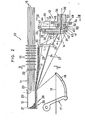
- FIGS. 1 and 2 generally indicated by the numeral 10.
- the apparatus includes a needle loom 11 of a known construction for producing a narrow, continuous slide fastener stringer tape 12, and a rotor assembly 13 disposed adjacent to the needle loom 11 for winding an element-forming monofilament 14 into a helically coiled coupling element as it is woven into the stringer tape 12 along a longitudinal edge thereof.
- the needle loom 11 comprises a group of harnesses 15 for forming sheds by raising and lowering warp threads 16 selectively, a weft inserter 17 having a filling carrier l8 for inserting a weft thread or filling 19 through the warp sheds, a latch needle 20 reciprocable in warp direction alongside of a longitudinal edge of the tape 12 for catching and knitting loops of the weft thread 19 carried by the filling carrier 18 so as to form a tape selvage 21 along the longitudinal tape edge, and a reed 22 for beating the weft thread 19 into the fell 23 of the tape 12 being woven.
- the rotor assembly 13 includes a mandrel 24 mounted on a mandrel support 25 and around which the monofilament 14 can be wound or coiled into a slide fastener coupling element 26.
- the monofilament 14 is made of plastic material and has a succession of widened, flattened portions 27 spaced at predetermined intervals therealong, such portions 27 being formed as by stamping.
- the widened, flattened portions 27 permit the monofilament 14 to be bent or folded over easily at such portions when the monofilament 14 is being coiled, and alternate widened, flattened portions 27 serve as coupling heads 28 of the element 26.
- a reinforcing core thread 29 is fed along the mandrel 24 and inserted through the coupling element 26 as helically formed on the mandrel 24.
- Binding warp threads 30 are selectively raised and lowered by a group of harnesses 31, and are interlaced with the weft thread 19 and the helically coiled monofilament 14 for binding and securing the coupling element 26 to the stringer tape 12.
- the rotor assembly 13 comprises a stationary shaft 34 supported immovably and nonrotatably by suitable means and having an axial hole 35 for passage therethrough of the core thread 29, and a circular guide disk 36 disposed eccentrically with respect to and extending substantially at a right angle to the stationary shaft 34.
- the guide disk 36 is composed of a pair of circular plates 37,38 secured together by a screw 39.
- the circular plate 38 includes a sleeve 40 fitted over a small-diameter end portion of the stationary shaft 34 and fixed thereto by a setscrew 41.
- the circular plates 37,38 jointly define an annular groove 42 opening radially outwardly and receiving an annular guide rotor 33 slidably rotatable around the guide disk 36.
- the guide rotor 33 has an axial guide hole 43 for passage therethrough of the monofilament 14 and an axial guide pin 44 that is located substantially in diametrically opposite relation to the guide hole 43.
- the circular plates 37,38 jointly have an axial hole 45 in alignment with the axial hole 35 in the stationary shaft 34 for allowing the core thread 14 to pass through the guide disk 36.
- the mandrel support 25 is fixedly mounted on the circular plate 37 by a screw 46.
- a radial arm 47 is mounted on the sleeve 40 for rotation therearound.
- the radial arm 47 has a radial slot 48 in which the guide pin 44 is slidably received.
- a drive gear 49 is rotatably mounted by a bearing 50 on the stationary shaft 34, and is drivable by a motor gear 51 held in mesh therewith.
- the radial arm 47 includes a flange 52 secured by a screw 53 to the drive gear 49, whereby the radial arm 47 can revolve with the drive gear 49 around the stationary shaft 34 upon rotation of the motor gear 51.
- the drive gear 49 has an axial guide hole 54 for passage therethrough of the monofilament 14.
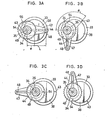
- Figures 2 and 3A illustrate a starting position in which the guide hole 43 in the guide rotor 47 is located farthest from the warp threads 16 and the guide pin 44 is located closest to the warp threads 16.
- the drive gear 49 is angularly moved clockwise in the direction of the arrow 56 through 90 degrees from the position of Figure 3A to that of Figure 3B
- the arm 47 is also angularly moved with the drive gear 49 through 90 degrees with the guide pin 44 as slidably guided in the slot 48 being angularly displaced through more than 90 degrees due to the eccentricity of the guide rotor 33 with respect to the stationary shaft 34.
- the guide hole 43 is therefore angularly moved through a corresponding angle of a which is approximately 129 degrees in the illustrated embodiment.
- the guide rotor 33 is angularly moved through approximately 51 degrees, whereupon the guide hole 43 is located closest to the warp threads 16.
- the guide hole 43 is further angularly moved through about 129 degrees from the position of Figure 3D back to the starting position of Figure 3A by continued 90-degree angular movement of the drive gear 49.
- the guide hole 43 angularly moves through only about 102 degrees, that is, it moves at a lower speed of rotation than that of the drive gear 49.
- the guide hole 43 angularly moves through about 258 degrees, that is, moves at a speed of rotation higher than that of the drive gear 49.
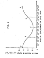
- Figure 4 is a diagram of the angular velocity of the rotor 33 which varies during one cycle of revolution as a function of angular displacement of the drive gear 49, it being assumed that the amount of eccentricity of the guide disk 36 with respect to the stationary shaft 34 is 12 mm, the distance between the axis of rotation of the rotor 33 and the central axis of the pin 44 is 20 mm, and the drive gear 49 is rotated at a constant angular velocity w (rad/sec).
- the angular velocities of the rotor 33 at the respective positions shown in Figures 3A through 3D correspond to the points a through d, respectively, on the curve illustrated in Figure 4.
- the harnesses 31 for the binding warp threads 30 are located off center with respect to a conical orbital path 55 for the monofilament 14 and as closely to the warp threads 16 as possible to maintain the binding warp threads 30 substantially parallel to the warp threads 16.
- the guide hole 43 and hence the monofilament l4 carried therein are relatively slow in their angular movement adjacent to the warp threads 16 during a half cycle of revolution of the drive gear 49, so that the harnesses 3l can be moved up and down across the conical orbital path 55 reliably without hitting the monofilament 14 being circled.
- the monofilament 14 angularly moves relatively rapidly through a portion of the conical orbital path 55 which is remote from the binding warp threads 30, and hence is free from interference with the harnesses 31.
- the speed of revolution of the drive gear 49 can therefore be increased as a whole for a larger rate of production of a slide fastener stringer inasmuch as the monofilament 14 moves adjacent to the warp threads 16 slowly enough to allow reliable operation of the harnesses 31.
- the tangential velocity V of the pin 44 on the rotor 33 can be determined by the formula:
- the speed of rotation of the guide hole 43 can thus be adjusted by selecting the distance L and the amount e of eccentricity. Stated otherwise, the interval of time in which the guide hole 43 moves angularly from the position of Figure 3B to the position of Figure 3D can be varied by changing these parameters L and e.
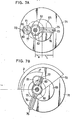
- a rotor assembly 60 as shown in Figures 6 and 7A - 7B comprises a stationary shaft 61 having a central axial hole 62 for passage therethrough of the monofilament 14, and a circular guide disk 63 attached eccentrically to the stationary shaft 61 lying in a plane extending at a right angle to the shaft 61.
- the guide disk 63 is comprised of a pair of circular plates 64,65 fixed together by a screw 66, the circular plate 65 being secured by a screw 67 to a sleeve 68 fitted over a small-diameter end portion of the stationary shaft 61.
- the sleeve 68 is nonrotatably fixed to the shaft 61 by a radially extending setscrew 69.
- An annular groove 70 is defined jointly by and between the circular plates 64,65, and an annular guide rotor 71 is rotatably received in the annular groove 70.
- the rotor 71 has an axial guide hole 72 and an axial pin 73 which are diametrically opposite to or angularly spaced 180 degrees from each other.
- the circular plate 64 has a hole 74 axially aligned for communication with the axial hole 62 for passage therethrough of the core thread 29.
- An arm 75 rotatably mounted on the sleeve 68 has a pair of diametrically opposite radial slots 76,77, the axial pin 73 on the rotor 71 being slidably received in the radial slot 76.
- a drive gear 78 is rotatably supported by a bearing 79 on the stationary shaft 61 and is held in mesh with a gear 80 drivable by a motor (not shown).
- the drive gear 78 supports an eccentric gear 81 mounted thereon by a pin 84 and meshing with a fixed gear.82 that is integral with the sleeve 68 and coaxial with the stationary shaft 61, the gears 81,82 having the same dimensions.
- the eccentric gear 81 has an axial off-center pin 83 slidably received in the radial slot 77 in the arm 75.
- the drive gear 78 is rotated to enable the eccentric gear 81 to revolve therewith around the stationary shaft 61 and at the same time to rotate about the pin 84 by meshing engagement with the fixed gear 82.
- the rotor 71 now starts rotating clockwise from the position of FIG. 7A.
- the drive gear 78 angularly moves through 90 degrees
- the arm 75 angularly moves through an angle of ⁇ ( Figure 7B) which is greater than 90 degrees because the gear 81 is turned about the pin 84 to advance the arm 75 angularly ahead of the drive gear 78 through angular displacement of the pin 83.
- the rotor 71 and hence the guide 72 therein are-angularly moved through an angle of y which is much greater than the angle S because of the pin 73 trapped radially movably in the radial slot 76 being angularly moved.
- the angle y is approximately 142.5 degrees in the illustrated embodiment.
- the drive gear 78 continues to move angularly through another 90 degrees, whereupon the arm 75 is angularly moved through 180 degrees from the starting position.
- the guide hole 72 is angularly moved through approximately 37.5 degrees from the position of Figure 7B to the position of Figure 7C wherein the guide hole 72 is located closest to the warp threads 16.
- the guide hole 72 angularly moves only through about 75 degrees and hence at a low speed of rotation. While the drive gear 78 is angularly moved from the position of Figure 7D through the position of Figure 7A to the position of Figure 7B, the guide hole 72 angularly moves through about 285 degrees and hence at a high speed of rotation.
- the tangential velocity of the pin 73 and hence the speed of rotation of the guide hole 72 can be adjusted by changing the distance L between the rotational axis of the rotor 71 and the central axis of the pin 73, the amount e of eccentricity of the guide disk 63 with respect to the shaft 61, and the amount r of eccentricity of the pin 83 with respect to the pin 84 of the gear 81. Accordingly, the interval of time in which the guide hole 72 moves from the position of Figure 7B to the position of Figure 7D can be varied by changing the parameters L, e and r.
- the fixed gear 82 has a radius of 12 mm, the distance L is 29 mm, and the drive gear 78 is rotated at a constant angular velocity w (rad/sec), the angular velocity of the rotor 71 changes as a function of the.angular displacement of the drive gear 78 as illustrated in Figure 8.
- the points a through d on the curve of Figure 8 correspond to the positions of Figures 7A through 7D, respectively.
- the rotor 71 according to the embodiment shown in Figure 6 angularly moves more rapidly during the interval between the Figure 7B and Figure 7D positions than the rotor 33 of the embodiment shown in Figure 2 angularly moves from the Figure 3B to the Figure 3D position.
Landscapes
- Engineering & Computer Science (AREA)
- Textile Engineering (AREA)
- Looms (AREA)
- Slide Fasteners (AREA)
- Braiding, Manufacturing Of Bobbin-Net Or Lace, And Manufacturing Of Nets By Knotting (AREA)
- Treatment Of Fiber Materials (AREA)
Applications Claiming Priority (2)
| Application Number | Priority Date | Filing Date | Title |
|---|---|---|---|
| JP54084657A JPS5933368B2 (ja) | 1979-07-04 | 1979-07-04 | 織込みスライドフアスナ−製造機におけるエレメント成形用線条の導入装置 |
| JP84657/79 | 1979-07-04 |
Publications (2)
| Publication Number | Publication Date |
|---|---|
| EP0022190A1 true EP0022190A1 (fr) | 1981-01-14 |
| EP0022190B1 EP0022190B1 (fr) | 1984-05-16 |
Family
ID=13836782
Family Applications (1)
| Application Number | Title | Priority Date | Filing Date |
|---|---|---|---|
| EP80103319A Expired EP0022190B1 (fr) | 1979-07-04 | 1980-06-13 | Appareil pour fabriquer un ruban de bande tissée pour fermeture à glissière |
Country Status (10)
| Country | Link |
|---|---|
| US (1) | US4331180A (fr) |
| EP (1) | EP0022190B1 (fr) |
| JP (1) | JPS5933368B2 (fr) |
| AU (1) | AU528782B2 (fr) |
| BR (1) | BR8004245A (fr) |
| CA (1) | CA1147537A (fr) |
| DE (1) | DE3067820D1 (fr) |
| ES (1) | ES493575A0 (fr) |
| HK (1) | HK20188A (fr) |
| MY (1) | MY8700567A (fr) |
Families Citing this family (1)
| Publication number | Priority date | Publication date | Assignee | Title |
|---|---|---|---|---|
| JPS5951814B2 (ja) * | 1980-12-18 | 1984-12-15 | ワイケイケイ株式会社 | 織り込みスライドフアスナ−とその製造装置 |
Citations (6)
| Publication number | Priority date | Publication date | Assignee | Title |
|---|---|---|---|---|
| FR2088507A1 (fr) * | 1970-05-12 | 1972-01-07 | Prym Werke William | |
| FR2235218A1 (fr) * | 1973-06-29 | 1975-01-24 | Prym Werke William | |
| FR2400860A1 (fr) * | 1977-08-27 | 1979-03-23 | Yoshida Kogyo Kk | Appareil pour la fabrication d'une ganse de fermeture a glissiere |
| GB2008159A (en) * | 1977-11-09 | 1979-05-31 | Yoshida Kogyo Kk | Apparatus for manufacturing a sliding clasp fastener stringer having a woven coeles coupling element |
| GB2033934A (en) * | 1978-10-24 | 1980-05-29 | Yoshida Kogyo Kk | Stringer tape loom |
| GB2034770A (en) * | 1978-11-20 | 1980-06-11 | Yoshida Kogyo Kk | Loom for weaving a slide fastener stringer having a woven coiled coupling element |
-
1979
- 1979-07-04 JP JP54084657A patent/JPS5933368B2/ja not_active Expired
-
1980
- 1980-06-13 EP EP80103319A patent/EP0022190B1/fr not_active Expired
- 1980-06-13 DE DE8080103319T patent/DE3067820D1/de not_active Expired
- 1980-06-19 AU AU59414/80A patent/AU528782B2/en not_active Expired
- 1980-07-02 US US06/165,293 patent/US4331180A/en not_active Expired - Lifetime
- 1980-07-03 CA CA000355368A patent/CA1147537A/fr not_active Expired
- 1980-07-04 BR BR8004245A patent/BR8004245A/pt not_active IP Right Cessation
- 1980-07-04 ES ES493575A patent/ES493575A0/es active Granted
-
1987
- 1987-12-30 MY MY567/87A patent/MY8700567A/xx unknown
-
1988
- 1988-03-17 HK HK201/88A patent/HK20188A/en not_active IP Right Cessation
Patent Citations (7)
| Publication number | Priority date | Publication date | Assignee | Title |
|---|---|---|---|---|
| FR2088507A1 (fr) * | 1970-05-12 | 1972-01-07 | Prym Werke William | |
| FR2235218A1 (fr) * | 1973-06-29 | 1975-01-24 | Prym Werke William | |
| US3941163A (en) * | 1973-06-29 | 1976-03-02 | William Prym-Werke Kg | Method of making a woven zipper |
| FR2400860A1 (fr) * | 1977-08-27 | 1979-03-23 | Yoshida Kogyo Kk | Appareil pour la fabrication d'une ganse de fermeture a glissiere |
| GB2008159A (en) * | 1977-11-09 | 1979-05-31 | Yoshida Kogyo Kk | Apparatus for manufacturing a sliding clasp fastener stringer having a woven coeles coupling element |
| GB2033934A (en) * | 1978-10-24 | 1980-05-29 | Yoshida Kogyo Kk | Stringer tape loom |
| GB2034770A (en) * | 1978-11-20 | 1980-06-11 | Yoshida Kogyo Kk | Loom for weaving a slide fastener stringer having a woven coiled coupling element |
Also Published As
| Publication number | Publication date |
|---|---|
| ES8102462A1 (es) | 1981-02-16 |
| JPS5611004A (en) | 1981-02-04 |
| AU5941480A (en) | 1981-01-15 |
| ES493575A0 (es) | 1981-02-16 |
| AU528782B2 (en) | 1983-05-12 |
| CA1147537A (fr) | 1983-06-07 |
| US4331180A (en) | 1982-05-25 |
| MY8700567A (en) | 1987-12-31 |
| BR8004245A (pt) | 1981-01-21 |
| JPS5933368B2 (ja) | 1984-08-15 |
| DE3067820D1 (en) | 1984-06-20 |
| EP0022190B1 (fr) | 1984-05-16 |
| HK20188A (en) | 1988-03-25 |
Similar Documents
| Publication | Publication Date | Title |
|---|---|---|
| US3941163A (en) | Method of making a woven zipper | |
| EP0022190B1 (fr) | Appareil pour fabriquer un ruban de bande tissée pour fermeture à glissière | |
| US4184518A (en) | Apparatus for manufacturing a slide fastener stringer having a woven coiled element | |
| US4263943A (en) | Apparatus for manufacturing a slide fastener stringer having a woven coiled coupling element | |
| EP0099063B1 (fr) | Appareil pour la frappe d'éléments d'accouplement hélicoidaux destinés à des fermetures à glissière | |
| US4278111A (en) | Apparatus for manufacturing a woven slide fastener stringer | |
| US4174736A (en) | Apparatus for manufacturing a slide fastener stringer having a woven coiled coupling element | |
| US3827463A (en) | Method of and apparatus for the production of a slide fastener | |
| US4287918A (en) | Apparatus for manufacturing a slide fastener stringer having a woven coiled coupling element | |
| US4557299A (en) | Method of and apparatus for selectively releasing a predetermined length of weft thread in shuttleless looms | |
| US4390046A (en) | Apparatus for manufacturing woven slide fastener stringers | |
| WO1993025742A1 (fr) | Procede et dispositif d'alimentation en fils de trame | |
| US3982566A (en) | Method and apparatus of making a woven zipper | |
| CS196342B2 (en) | Method of and apparatus for forming fabric selvedge | |
| US3828825A (en) | Apparatus for manufacturing sliding clasp fasteners having coupling links woven into the edge of a supporting tape | |
| JPS6118054Y2 (fr) | ||
| DE22190T1 (de) | Vorrichtung zum Herstellen eines gewebten Reißverschlußträgerbandes | |
| DE2516130A1 (de) | Bandwebmaschine zum herstellen von reissverschluessen | |
| CN209602715U (zh) | 一种可实现经纬向同步送料的无梭织机 | |
| KR820000266B1 (ko) | 코일상의 파스너 엘레멘트를 가진 직입 슬라이드 파스너의 제조장치 | |
| KR800000470Y1 (ko) | 직기에 있어서 이(耳) 형성장치의 구동장치 | |
| PL41644B1 (fr) | ||
| JPS58202262A (ja) | 自動管巻き機 | |
| GB2031965A (en) | Improvements in or relating to apparatuses for winding weft threads onto spools of carriers in travelling-wave looms | |
| PL42255B1 (fr) |
Legal Events
| Date | Code | Title | Description |
|---|---|---|---|
| PUAI | Public reference made under article 153(3) epc to a published international application that has entered the european phase |
Free format text: ORIGINAL CODE: 0009012 |
|
| AK | Designated contracting states |
Designated state(s): BE CH DE FR GB IT NL |
|
| ITCL | It: translation for ep claims filed |
Representative=s name: JACOBACCI CASETTA & PERANI S.P.A. |
|
| 17P | Request for examination filed |
Effective date: 19810414 |
|
| DET | De: translation of patent claims | ||
| ITF | It: translation for a ep patent filed | ||
| GRAA | (expected) grant |
Free format text: ORIGINAL CODE: 0009210 |
|
| AK | Designated contracting states |
Designated state(s): BE CH DE FR GB IT LI NL |
|
| REF | Corresponds to: |
Ref document number: 3067820 Country of ref document: DE Date of ref document: 19840620 |
|
| ET | Fr: translation filed | ||
| PLBE | No opposition filed within time limit |
Free format text: ORIGINAL CODE: 0009261 |
|
| STAA | Information on the status of an ep patent application or granted ep patent |
Free format text: STATUS: NO OPPOSITION FILED WITHIN TIME LIMIT |
|
| 26N | No opposition filed | ||
| ITTA | It: last paid annual fee | ||
| REG | Reference to a national code |
Ref country code: CH Ref legal event code: PFA Free format text: YKK CORPORATION |
|
| ITPR | It: changes in ownership of a european patent |
Owner name: CAMBIO RAGIONE SOCIALE;YKK CORPORATION |
|
| REG | Reference to a national code |
Ref country code: FR Ref legal event code: CD |
|
| NLT1 | Nl: modifications of names registered in virtue of documents presented to the patent office pursuant to art. 16 a, paragraph 1 |
Owner name: YKK CORPORATION TE TOKIO, JAPAN. |
|
| PGFP | Annual fee paid to national office [announced via postgrant information from national office to epo] |
Ref country code: FR Payment date: 19990310 Year of fee payment: 20 |
|
| PGFP | Annual fee paid to national office [announced via postgrant information from national office to epo] |
Ref country code: BE Payment date: 19990323 Year of fee payment: 20 |
|
| PGFP | Annual fee paid to national office [announced via postgrant information from national office to epo] |
Ref country code: GB Payment date: 19990609 Year of fee payment: 20 Ref country code: CH Payment date: 19990609 Year of fee payment: 20 |
|
| PGFP | Annual fee paid to national office [announced via postgrant information from national office to epo] |
Ref country code: NL Payment date: 19990630 Year of fee payment: 20 |
|
| PGFP | Annual fee paid to national office [announced via postgrant information from national office to epo] |
Ref country code: DE Payment date: 19990728 Year of fee payment: 20 |
|
| BE20 | Be: patent expired |
Free format text: 20000613 *YKK CORP. |
|
| PG25 | Lapsed in a contracting state [announced via postgrant information from national office to epo] |
Ref country code: LI Free format text: LAPSE BECAUSE OF NON-PAYMENT OF DUE FEES Effective date: 20000612 Ref country code: GB Free format text: LAPSE BECAUSE OF EXPIRATION OF PROTECTION Effective date: 20000612 Ref country code: CH Free format text: LAPSE BECAUSE OF NON-PAYMENT OF DUE FEES Effective date: 20000612 |
|
| PG25 | Lapsed in a contracting state [announced via postgrant information from national office to epo] |
Ref country code: NL Free format text: LAPSE BECAUSE OF EXPIRATION OF PROTECTION Effective date: 20000613 |
|
| REG | Reference to a national code |
Ref country code: GB Ref legal event code: PE20 Effective date: 20000612 |
|
| REG | Reference to a national code |
Ref country code: CH Ref legal event code: PL |
|
| NLV7 | Nl: ceased due to reaching the maximum lifetime of a patent |
Effective date: 20000613 |