EP0022363A1 - Positions- oder Bewegungsdetektor, z.B. für Beförderungsmittel wie Aufzüge - Google Patents
Positions- oder Bewegungsdetektor, z.B. für Beförderungsmittel wie Aufzüge Download PDFInfo
- Publication number
- EP0022363A1 EP0022363A1 EP80302273A EP80302273A EP0022363A1 EP 0022363 A1 EP0022363 A1 EP 0022363A1 EP 80302273 A EP80302273 A EP 80302273A EP 80302273 A EP80302273 A EP 80302273A EP 0022363 A1 EP0022363 A1 EP 0022363A1
- Authority
- EP
- European Patent Office
- Prior art keywords
- cable
- cage
- standing wave
- resonator
- movement
- Prior art date
- Legal status (The legal status is an assumption and is not a legal conclusion. Google has not performed a legal analysis and makes no representation as to the accuracy of the status listed.)
- Ceased
Links
- 239000004020 conductor Substances 0.000 claims description 6
- 239000000523 sample Substances 0.000 abstract description 16
- 238000001514 detection method Methods 0.000 abstract description 5
- 238000004891 communication Methods 0.000 description 5
- 238000012544 monitoring process Methods 0.000 description 4
- 230000005540 biological transmission Effects 0.000 description 3
- 238000005259 measurement Methods 0.000 description 3
- 238000004804 winding Methods 0.000 description 3
- 238000010586 diagram Methods 0.000 description 2
- 238000010521 absorption reaction Methods 0.000 description 1
- 230000003321 amplification Effects 0.000 description 1
- 230000003466 anti-cipated effect Effects 0.000 description 1
- 238000009954 braiding Methods 0.000 description 1
- 238000010276 construction Methods 0.000 description 1
- 238000011109 contamination Methods 0.000 description 1
- 230000000694 effects Effects 0.000 description 1
- 238000000034 method Methods 0.000 description 1
- 238000012986 modification Methods 0.000 description 1
- 230000004048 modification Effects 0.000 description 1
- 238000003199 nucleic acid amplification method Methods 0.000 description 1
- 230000003287 optical effect Effects 0.000 description 1
- 230000003534 oscillatory effect Effects 0.000 description 1
- 230000003071 parasitic effect Effects 0.000 description 1
- 229920003023 plastic Polymers 0.000 description 1
- 239000004033 plastic Substances 0.000 description 1
- 230000011664 signaling Effects 0.000 description 1
Images




Classifications
-
- G—PHYSICS
- G01—MEASURING; TESTING
- G01D—MEASURING NOT SPECIALLY ADAPTED FOR A SPECIFIC VARIABLE; ARRANGEMENTS FOR MEASURING TWO OR MORE VARIABLES NOT COVERED IN A SINGLE OTHER SUBCLASS; TARIFF METERING APPARATUS; MEASURING OR TESTING NOT OTHERWISE PROVIDED FOR
- G01D5/00—Mechanical means for transferring the output of a sensing member; Means for converting the output of a sensing member to another variable where the form or nature of the sensing member does not constrain the means for converting; Transducers not specially adapted for a specific variable
- G01D5/48—Mechanical means for transferring the output of a sensing member; Means for converting the output of a sensing member to another variable where the form or nature of the sensing member does not constrain the means for converting; Transducers not specially adapted for a specific variable using wave or particle radiation means
-
- B—PERFORMING OPERATIONS; TRANSPORTING
- B66—HOISTING; LIFTING; HAULING
- B66B—ELEVATORS; ESCALATORS OR MOVING WALKWAYS
- B66B1/00—Control systems of elevators in general
- B66B1/34—Details, e.g. call counting devices, data transmission from car to control system, devices giving information to the control system
- B66B1/3492—Position or motion detectors or driving means for the detector
Definitions
- This invention relates to a position or movement sensor.
- the invention is in particular applicable to systems for monitoring the position or movement of a conveyance such as a lift (or elevator) .
- a conveyance such as a lift (or elevator) .
- An example of such an application is with mine cages, which are used for transporting miners and equipment up and down mine shafts.
- Leaky radiating cables are known for use in communication systems, particularly for use in railway systems and mines. The idea of using such a cable for communication purposes has been known for many years (see N. Monk and H.S. Winbigler "Communication with moving trains in tunnels" IRE Trans. Vehic. Comm. , Dec. 1956, PGVC-7, pages 21 to 28).
- Such cables are usually coaxial cables and differ from a standard braided type of cable in that the outer conductor is incomplete, having an overall optical cover typically of 60 to 70%. This may be achieved by opening out the braiding, or by forming the outer conductor with slots or holes.
- the cables have the advantage that attenuation along the cable is very little influenced by contamination and moisture on the cable surface.
- Such cables can be obtained for example from BICC Wiring and General Cables Division, Helsby, Warrington, Lancashire, England.
- a brief outline of the theory of such cables is to be found in Electronics Letters VOL.8, No. 18, 7th September, 1972, pages 465 to 466, and examples of their use in "Radiocommunications in Confined Spaces" Pye Telecom Engineering Notes, publication TSP 394/1. Fuller theoretical details are to be found in the various papers presented at the Colloquium on Leaky Feeder Radio Communication Systems held at the University of Surrey, Guildford from 8th to lOth April, 1974.
- leaky radiating cables of this type are particularly suitable for use in a sensor embodying this invention.
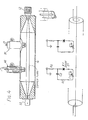
- the sensor 10 includes a leaky radiating cable 12 typically of one inch (25mm) diameter which extends between a coaxial cavity 14 at one end and a terminating impedance 16 at the other end.
- An R.F. signal source 20 feeds the cavity 14 via a coaxial feeder 22.
- the source is initially tuned to set up a standing wave in the cable 12, as indicated diagrammatically at 24.
- the load impedance 16 is tuned so as to give the most suitable voltage standing wave ratio.
- the object 26 to be monitored moves parallel to the cable 12 and carries a passive resonator 28 which is likewise tuned to the source frequency.
- the resonator does not contact the cable 12, but is placed on the object 26 so as to be close to the cable.
- the resonator 28 can take the form of a dipole aerial; examples of suitable resonators are given below with reference to Figs. 5 and 6.
- standing waves are undesirable and steps are taken to reduce them.
- This invention is based on the appreciation that such standing waves can in fact provide a particularly elegant way of sensing position or movement.
- the standing waves define a reference which depends only on the frequency of the source and the propagation velocity of the wave in the cable. If frequencies greater than 10 MHz are used, then the wavelength will be less than 30 metres and nodes will occur down the cable at intervals of not more than 15 metres. These nodes and/or the antinodes can be detected and counted to give a distance measure in terms of the number of wavelengths traversed by the object.
- the measurement could be made by detection equipment on the object 26 itself. However, it is preferred to have the measuring equipment at one end of the cable.
- a detector probe 30 is incorporated in the cavity 14 and is connected to a detection circuitry 32, described below, to monitor the characteristics of the standing wave pattern.
- the resonator when placed adjacent to the nodes on the leaky transmission line will cause a change in - the characteristics of the standing wave. As the resonator moves along the cable, there will be a cyclical change in the characteristics as the object passes each node. Monitoring these characteristics enables the movement of the object to be detected.
- the characteristic detected may be phase, current or voltage.
- Fig. 2 illustrates the use of the sensor to monitor movement of a mine cage.
- the mine cage 26 is in a vertical shaft 34, and the resonator 28 is mounted at any convenient point on the outside of the cage adjacent to the cable 12.
- the cable 12 runs down the shaft 34 and is attached to the shaft at intervals.
- the cavity 14 is mounted at the shaft head, and the source and detector are at any convenient remote location.
- the system does not rely on detecting the winding of the main cable or hawser 36, nor are electrical cables required from the mine cage 26 to the winding control room.
- the sensor could be used in other systems where movement detection is required.
- Such systems would include objects moving in horizontal or sloping tunnels, transporting or haulage systems such as tracked conveyances or underground railway systems whether in a mine or public transport system, and numerous other types of moving machinery or vehicles.
- R.F. source 20 includes an oscillator 40 coupled through an R.F. amplifier 42 and a filter 44 to the feeder 22 and hence to the.probe cavity 14.
- the cavity operates as a reflectometer and includes in addition to the detector probe 30, a second probe 46 which monitors the amplitude of the standing wave and applies it to a meter 48. The meter reading is used in the manual adjustment of the oscillator 40 in the setting up of the system.
- the cable 12 has a continuous slot axially disposed along the length of the cable, and provides a polar radiating characteristic with a fixed major lobe.
- the resonator 28 is positioned to be in the direction of this lobe.
- the detector circuit 32 is connected to the detector probe 30. This probe 30 forms the datum position with respect to which distances are measured.
- the probe output is applied to a rectifying amplifier 50, which is in turn connected to an analogue to digital converter 52, and a counter 54.
- the counter holds a count which represents the number of standing wave nodes which the resonator has passed in moving from a reference position.
- the count is applied in multiplexed -form to a display 58. This is a position display and is scaled to show the number of feet or metres by which the cage 26 has descended.
- the signal received by the detector 32 as the cage moves is a sine wave in which each pulse or cycle corresponds to one wavelength travelled.
- the measurement is thus made in terms of the number of wavelengths.
- the wavelength can be accurately known and thus the measurement can be converted to feet or metres.
- the amplitude of the signal from the probe after rectification and amplification in amplifier 50 varies between a maximum value when the resonator 28 is at a node of the standing wave pattern to a minimum value at an anti-node with a sinusoidal waveform in between.
- the converter 52 converts the signal amplitude into a linear waveform representative of distance. Whenever the maximum or minimum value is reached the converter is switched over so as to continue adding distance increments despite the fact that the signal is now changing in the opposite direction.
- suitable logic circuitry is provided to determine the direction of change of the signal.
- the counter 54 thus holds a count which defines the distance travelled by the cage 36 to an accuracy of a small fraction of a wavelength, e.g. a few centimetres.
- a rate comparator 60 determines the rate of change of the count in counter 54. This is a measure of the speed of the cage, and is applied to a velocity display 64, in feet or metres per second.
- the system can be electronically zeroed to any desired reference position, by presetting the.count in counter 54 by means of logic circuitry 66, the accuracy of the positioning of the cable and the cavity 14 is unimportant.
- the output from the analogue to digital converter 52 can also be used to control the movement of the cage, e.g. to slow it when approaching a level at which it is to stop and to stop it at the appropriate point.
- the signals can also be compared with signals from the winding machinery to indicate rope slip.
- the oscillator frequency used is related to the linear resolution required, the best transmission line stability, the most advantageous transmission line current, and other factors affecting the stability of the standing waves. It is anticipated that frequencies in the range 150 MHz to 1000 MHz may be suitable.
- Fig. 4 also illustrates the theoretical equivalent circuits for the probes 30 and 46.
- the probe 30 detects the reflected standing wave and the probe 46 detects the forward standing wave.
- Probe 30 is used to detect a change in a characteristic of the standing wave which will occur when the resonator is coincident with a standing wave anti-node.
- Figs. 5 and 6 Two possible forms for the resonator 28 are shown in Figs. 5 and 6 respectively. In its simplest form it is: ahalf-wave dipole.
- the resonator of Fig. 5 includes a folded dipole 80 and a director element 82. The dipole is tuned by an impedance 84.
- the resonator of Fig. 5 relies on parasitic resonance by absorption and reflection.
- the unit is preferably enclosed in a plastics cover which can be bolted onto the cage 36 without modification of the cage. '
- a -multi-element resonator is shown in Fig. 6, which includes more complex circuitry 86 connected to the dipole 80 and to an exciter element 88.
- an R.F. diode is used as a detector stage and a varactor diode is used as an oscillatory element to feed the exciter element.
- the resonator can be turned into an active resonator by the addition of a low-power source such as battery across the terminals X-X, if this is found to be necessary.
- a narrow band frequency modulated signal (N.B.F.M.) may be used.
- N.B.F.M. narrow band frequency modulated signal
- a system of frequency pulse modulation might be used either in the indirect or direct phase mode.
- the resonator is in fact an aerial driven into resonance by the standing wave current.
- a separate N.B.F.M. signal might be used for each cage to identify with its particular resonator.
- the stage after detection at the cavity probe will then -include a discriminator circuit.
- the standing wave nodes will be constantly changing, and this will be further complicated by the fact that more than one FM signal may be transmitted on the feeder cable if a multiple cage system is used.
- the transmitted signal, one for each cage must be accurately strobed, and the strobed sync pulse will be fed by suitable circuitry into the logic circuitry after the analogue to digital converter.
- a sample of part of the standing wave complex signal that is typical of a particular -cage signal can be logically processed and read out on the digit display peculiar to that cage.
- Another method of approaching this problem would be to use a microprocessor with a dedicated firmware programme to perform a fast Fourier transform in real time and multiplexed directly to the logic circuitry.
- the oscillator output would be modulated and variations in output current will occur.
- the oscillator 40 would be controlled by a feedback loop from the probe 46 to maintain the desired signal amplitude.
- the system illustrated has a number of advantages. It is electronic and has no moving parts which are liable to wear.
- the output signals are readily derived in digital form and can easily be interfaced with digital control circuitry. Also, high resolution can be obtained irrespective of cable length, so long as the standing wave can be set up.
Landscapes
- Engineering & Computer Science (AREA)
- Automation & Control Theory (AREA)
- Physics & Mathematics (AREA)
- General Physics & Mathematics (AREA)
- Computer Networks & Wireless Communication (AREA)
- Geophysics And Detection Of Objects (AREA)
- Measurement Of Length, Angles, Or The Like Using Electric Or Magnetic Means (AREA)
- Radar Systems Or Details Thereof (AREA)
Applications Claiming Priority (2)
| Application Number | Priority Date | Filing Date | Title |
|---|---|---|---|
| GB7923672A GB2053480B (en) | 1979-07-06 | 1979-07-06 | Position or movement sensor |
| GB7923672 | 1979-07-06 |
Publications (1)
| Publication Number | Publication Date |
|---|---|
| EP0022363A1 true EP0022363A1 (de) | 1981-01-14 |
Family
ID=10506354
Family Applications (1)
| Application Number | Title | Priority Date | Filing Date |
|---|---|---|---|
| EP80302273A Ceased EP0022363A1 (de) | 1979-07-06 | 1980-07-04 | Positions- oder Bewegungsdetektor, z.B. für Beförderungsmittel wie Aufzüge |
Country Status (8)
| Country | Link |
|---|---|
| US (1) | US4342021A (de) |
| EP (1) | EP0022363A1 (de) |
| AU (1) | AU6015080A (de) |
| CA (1) | CA1146233A (de) |
| GB (1) | GB2053480B (de) |
| ZA (1) | ZA803956B (de) |
| ZM (1) | ZM5880A1 (de) |
| ZW (1) | ZW15480A1 (de) |
Cited By (5)
| Publication number | Priority date | Publication date | Assignee | Title |
|---|---|---|---|---|
| FR2523719A1 (fr) * | 1982-03-17 | 1983-09-23 | Merlin Gerin | Detecteur de position d'un element mobile, notamment d'une barre de controle d'un reacteur nucleaire |
| GB2146864A (en) * | 1983-09-14 | 1985-04-24 | David James Reginald Martin | Vehicle location system |
| EP0266606A3 (en) * | 1986-11-03 | 1989-06-28 | Vickers, Incorporated | Position determining apparatus |
| EP0694792A1 (de) * | 1994-07-28 | 1996-01-31 | K.A. SCHMERSAL GmbH & Co. | Einrichtung zur Positionserfassung |
| DE102014000503A1 (de) * | 2014-01-20 | 2015-07-23 | Sew-Eurodrive Gmbh & Co Kg | System und Verfahren zur Erfassung der relativen Lage zweier Teile |
Families Citing this family (6)
| Publication number | Priority date | Publication date | Assignee | Title |
|---|---|---|---|---|
| GB2154742B (en) * | 1984-02-21 | 1987-12-02 | Edeco Petroleum Services | Measuring length of electrical conductor |
| CA2105409A1 (en) * | 1993-09-02 | 1995-03-03 | Frank Chalmers | Communication system for use in a mine |
| CN100361167C (zh) * | 2006-02-17 | 2008-01-09 | 南京泰通科技有限公司 | 漏缆工作状态监控系统及其监控方法 |
| DE102007037723A1 (de) * | 2007-08-09 | 2009-02-12 | Fachhochschule Gießen-Friedberg | Positionsbestimmung eines mobilen Funkgerätes in Bezug auf Leckwellenleiter |
| US8121805B2 (en) * | 2009-09-30 | 2012-02-21 | Mitsubishi Electric Research Laboratories, Inc. | Method and system for determining locations of moving objects with maximum length sequences |
| EP3403971B1 (de) * | 2017-05-19 | 2020-10-21 | KONE Corporation | Verfahren zur durchführung eines handantriebs in einem aufzug nach einer stromnetzabschaltung |
Citations (4)
| Publication number | Priority date | Publication date | Assignee | Title |
|---|---|---|---|---|
| US3648228A (en) * | 1970-02-09 | 1972-03-07 | Bendix Corp | Control system for vehicles |
| US3757330A (en) * | 1971-11-29 | 1973-09-04 | Atomic Energy Authority Uk | Microwave interferometers |
| FR2192344A1 (de) * | 1972-07-07 | 1974-02-08 | Thomson Csf | |
| DE2610127A1 (de) * | 1976-03-11 | 1977-09-22 | Roland Dipl Ing Kissling | Vorrichtung zur absolutwertmessung von bewegungsstrecken an maschinen |
Family Cites Families (6)
| Publication number | Priority date | Publication date | Assignee | Title |
|---|---|---|---|---|
| US2580155A (en) * | 1949-06-04 | 1951-12-25 | Westinghouse Air Brake Co | Proximity detector employing microwaves |
| GB1113665A (en) * | 1964-04-30 | 1968-05-15 | Hitachi Ltd | Leaky waveguide aerials |
| JPS515308B1 (de) * | 1969-11-25 | 1976-02-19 | ||
| US3668625A (en) * | 1970-09-21 | 1972-06-06 | David Wolf | Monitoring system |
| CA1093655A (en) * | 1977-01-19 | 1981-01-13 | Martin T. Cole | Intrusion or movement detector |
| US4218671A (en) * | 1977-10-10 | 1980-08-19 | Coal Industry (Patents) Limited | Mine cage position describer |
-
1979
- 1979-07-06 GB GB7923672A patent/GB2053480B/en not_active Expired
-
1980
- 1980-07-01 ZA ZA00803956A patent/ZA803956B/xx unknown
- 1980-07-03 US US06/165,828 patent/US4342021A/en not_active Expired - Lifetime
- 1980-07-04 ZM ZM58/80A patent/ZM5880A1/xx unknown
- 1980-07-04 ZW ZW154/80A patent/ZW15480A1/xx unknown
- 1980-07-04 CA CA000355488A patent/CA1146233A/en not_active Expired
- 1980-07-04 EP EP80302273A patent/EP0022363A1/de not_active Ceased
- 1980-07-04 AU AU60150/80A patent/AU6015080A/en not_active Abandoned
Patent Citations (4)
| Publication number | Priority date | Publication date | Assignee | Title |
|---|---|---|---|---|
| US3648228A (en) * | 1970-02-09 | 1972-03-07 | Bendix Corp | Control system for vehicles |
| US3757330A (en) * | 1971-11-29 | 1973-09-04 | Atomic Energy Authority Uk | Microwave interferometers |
| FR2192344A1 (de) * | 1972-07-07 | 1974-02-08 | Thomson Csf | |
| DE2610127A1 (de) * | 1976-03-11 | 1977-09-22 | Roland Dipl Ing Kissling | Vorrichtung zur absolutwertmessung von bewegungsstrecken an maschinen |
Non-Patent Citations (1)
| Title |
|---|
| ELECTRONICS LETTERS, Vol. 12, 28th October 1976 Stevenhage GB N.A. MACKAY et al.: "High-resolution guided RADAR system", pages 583, 584. * The whole document * * |
Cited By (9)
| Publication number | Priority date | Publication date | Assignee | Title |
|---|---|---|---|---|
| FR2523719A1 (fr) * | 1982-03-17 | 1983-09-23 | Merlin Gerin | Detecteur de position d'un element mobile, notamment d'une barre de controle d'un reacteur nucleaire |
| US4604576A (en) * | 1982-03-17 | 1986-08-05 | Merlin Gerin | Electromagnetic delay line incorporated in a position detector for a movable nuclear reactor control rod |
| GB2146864A (en) * | 1983-09-14 | 1985-04-24 | David James Reginald Martin | Vehicle location system |
| EP0266606A3 (en) * | 1986-11-03 | 1989-06-28 | Vickers, Incorporated | Position determining apparatus |
| EP0694792A1 (de) * | 1994-07-28 | 1996-01-31 | K.A. SCHMERSAL GmbH & Co. | Einrichtung zur Positionserfassung |
| US5736695A (en) * | 1994-07-28 | 1998-04-07 | K.A. Schmersal Gmbh & Co. | Device for detecting position |
| DE102014000503A1 (de) * | 2014-01-20 | 2015-07-23 | Sew-Eurodrive Gmbh & Co Kg | System und Verfahren zur Erfassung der relativen Lage zweier Teile |
| DE102014000503B4 (de) | 2014-01-20 | 2018-06-28 | Sew-Eurodrive Gmbh & Co Kg | System und Verfahren zur Erfassung der relativen Lage zweier Teile |
| EP3097381B1 (de) * | 2014-01-20 | 2021-03-24 | Sew-Eurodrive GmbH & Co. KG | System und verfahren zur erfassung der relativen lage zweier teile |
Also Published As
| Publication number | Publication date |
|---|---|
| GB2053480A (en) | 1981-02-04 |
| ZA803956B (en) | 1981-08-26 |
| CA1146233A (en) | 1983-05-10 |
| ZW15480A1 (en) | 1982-02-03 |
| GB2053480B (en) | 1983-05-18 |
| AU6015080A (en) | 1981-01-15 |
| ZM5880A1 (en) | 1982-03-22 |
| US4342021A (en) | 1982-07-27 |
Similar Documents
| Publication | Publication Date | Title |
|---|---|---|
| US4342021A (en) | Position or movement sensor, e.g. for conveyances such as lifts | |
| US4985705A (en) | Method and apparatus for compiling and evaluating local traffic data | |
| US4389645A (en) | Well logging fiber optic communication system | |
| US2818732A (en) | Device for remote temperature measurement | |
| KR100799275B1 (ko) | 거리측정장치, 거리측정설비 및 거리측정방법 | |
| FI83999C (fi) | Foerfarande och anordning foer maetning av hastigheten av ett objekt genom att utnyttja doppler -foerskjutningen av elektromagnetisk straolning. | |
| US4599618A (en) | Nearest return tracking in an FMCW system | |
| US4041495A (en) | Apparatus for determining the position of a object | |
| US4210902A (en) | Device for telemetering loads on power transmission line conductors | |
| US4887069A (en) | Perimeter intrusion detection system with block ranging capabilities | |
| US4053877A (en) | Method of and apparatus for surveying an area | |
| US5525976A (en) | Temperature measuring system | |
| FI91809B (fi) | Menetelmä ja laite liikkuvan kohteen nopeuden mittaamiseksi sähkömagneettisen säteilyn Doppler-siirtymää hyväksikäyttäen | |
| US5557281A (en) | Device for measuring the velocity of vehicles for traffic monitoring | |
| JP7276709B2 (ja) | 生体情報検出装置 | |
| WO2019125197A1 (ru) | Способ и система автоматического контроля контактного провода электротранспорта | |
| CN117805800A (zh) | 一种基于毫米波雷达的皮带测速方法及系统 | |
| NO304125B1 (no) | FremgangsmÕte og anordning for Õ overvÕke tilstanden for en mottakerantenne | |
| US3548310A (en) | Antenna current distribution measurement system | |
| JP3150765B2 (ja) | 送電線近接監視システム | |
| EP0416745A2 (de) | Alarmsystem für Eindringlinge | |
| AU6265200A (en) | Data transmission of control information by means of a telemeter | |
| SU1191405A1 (ru) | Способ контрол перемещени подъемного сосуда в стволе шахты и устройство дл его осуществлени | |
| DE69907760D1 (de) | Elektronische anwesenheitsüberwachung | |
| JPS5513404A (en) | Self-detector for stop position of moving object |
Legal Events
| Date | Code | Title | Description |
|---|---|---|---|
| PUAI | Public reference made under article 153(3) epc to a published international application that has entered the european phase |
Free format text: ORIGINAL CODE: 0009012 |
|
| AK | Designated contracting states |
Designated state(s): BE DE FR SE |
|
| 17P | Request for examination filed |
Effective date: 19810624 |
|
| STAA | Information on the status of an ep patent application or granted ep patent |
Free format text: STATUS: THE APPLICATION HAS BEEN REFUSED |
|
| 18R | Application refused |
Effective date: 19830819 |
|
| RIN1 | Information on inventor provided before grant (corrected) |
Inventor name: SCHALLER, RONALD WILLIAM |