EP0022656B1 - Antennesystem mit steuerbarem Strahlungsdiagramm - Google Patents
Antennesystem mit steuerbarem Strahlungsdiagramm Download PDFInfo
- Publication number
- EP0022656B1 EP0022656B1 EP80302320A EP80302320A EP0022656B1 EP 0022656 B1 EP0022656 B1 EP 0022656B1 EP 80302320 A EP80302320 A EP 80302320A EP 80302320 A EP80302320 A EP 80302320A EP 0022656 B1 EP0022656 B1 EP 0022656B1
- Authority
- EP
- European Patent Office
- Prior art keywords
- antenna
- signal
- directivity
- mixer
- dipole
- Prior art date
- Legal status (The legal status is an assumption and is not a legal conclusion. Google has not performed a legal analysis and makes no representation as to the accuracy of the status listed.)
- Expired
Links
- 239000003990 capacitor Substances 0.000 claims description 15
- 238000001514 detection method Methods 0.000 claims description 7
- 230000010363 phase shift Effects 0.000 claims description 7
- 230000005540 biological transmission Effects 0.000 claims description 3
- 238000012545 processing Methods 0.000 claims description 2
- 238000003491 array Methods 0.000 claims 1
- 238000010586 diagram Methods 0.000 description 11
- 230000035945 sensitivity Effects 0.000 description 6
- 239000000654 additive Substances 0.000 description 5
- 230000000996 additive effect Effects 0.000 description 5
- 230000008859 change Effects 0.000 description 5
- 230000005855 radiation Effects 0.000 description 5
- 230000000903 blocking effect Effects 0.000 description 4
- 230000006870 function Effects 0.000 description 3
- XEEYBQQBJWHFJM-UHFFFAOYSA-N Iron Chemical compound [Fe] XEEYBQQBJWHFJM-UHFFFAOYSA-N 0.000 description 2
- 230000003044 adaptive effect Effects 0.000 description 2
- 230000000694 effects Effects 0.000 description 2
- 239000011888 foil Substances 0.000 description 2
- 230000004044 response Effects 0.000 description 2
- 238000012546 transfer Methods 0.000 description 2
- RYGMFSIKBFXOCR-UHFFFAOYSA-N Copper Chemical compound [Cu] RYGMFSIKBFXOCR-UHFFFAOYSA-N 0.000 description 1
- 239000004411 aluminium Substances 0.000 description 1
- 229910052782 aluminium Inorganic materials 0.000 description 1
- XAGFODPZIPBFFR-UHFFFAOYSA-N aluminium Chemical compound [Al] XAGFODPZIPBFFR-UHFFFAOYSA-N 0.000 description 1
- 230000003321 amplification Effects 0.000 description 1
- 230000008901 benefit Effects 0.000 description 1
- 238000004891 communication Methods 0.000 description 1
- 239000002131 composite material Substances 0.000 description 1
- 238000010276 construction Methods 0.000 description 1
- 229910052802 copper Inorganic materials 0.000 description 1
- 239000010949 copper Substances 0.000 description 1
- 230000003247 decreasing effect Effects 0.000 description 1
- 238000011161 development Methods 0.000 description 1
- 238000005516 engineering process Methods 0.000 description 1
- 229910052742 iron Inorganic materials 0.000 description 1
- 229910052751 metal Inorganic materials 0.000 description 1
- 239000002184 metal Substances 0.000 description 1
- 238000000034 method Methods 0.000 description 1
- 230000004048 modification Effects 0.000 description 1
- 238000012986 modification Methods 0.000 description 1
- 238000003199 nucleic acid amplification method Methods 0.000 description 1
- 230000009467 reduction Effects 0.000 description 1
Images









Classifications
-
- H—ELECTRICITY
- H01—ELECTRIC ELEMENTS
- H01Q—ANTENNAS, i.e. RADIO AERIALS
- H01Q3/00—Arrangements for changing or varying the orientation or the shape of the directional pattern of the waves radiated from an antenna or antenna system
- H01Q3/44—Arrangements for changing or varying the orientation or the shape of the directional pattern of the waves radiated from an antenna or antenna system varying the electric or magnetic characteristics of reflecting, refracting, or diffracting devices associated with the radiating element
-
- H—ELECTRICITY
- H01—ELECTRIC ELEMENTS
- H01Q—ANTENNAS, i.e. RADIO AERIALS
- H01Q3/00—Arrangements for changing or varying the orientation or the shape of the directional pattern of the waves radiated from an antenna or antenna system
- H01Q3/26—Arrangements for changing or varying the orientation or the shape of the directional pattern of the waves radiated from an antenna or antenna system varying the relative phase or relative amplitude of energisation between two or more active radiating elements; varying the distribution of energy across a radiating aperture
- H01Q3/2605—Array of radiating elements provided with a feedback control over the element weights, e.g. adaptive arrays
- H01Q3/2611—Means for null steering; Adaptive interference nulling
- H01Q3/2617—Array of identical elements
- H01Q3/2623—Array of identical elements composed of two antennas
Definitions
- This invention relates to a directivity-controllable antenna system for receiving television wave signals in VHF and UHF bands and FM radio wave signals and also relates to a transmitting-receiving antenna system for other communications.
- the present invention is directed to electronically controlling the direction of directivity antenna systems which eliminates the above- mentioned disadvantages.
- variable directional antenna have already been proposed and are often known as adaptive antennas. Much development work has been undertaken in relation to such antennas and it is also known that variable capacitors can be used for controlling antenna reactance as disclosed in patent specification U.S.-A-3,209,358 and in Electronics Letters, Volume 9 No. 19. The use of an impedance adjusting capacitor across the terminals of a dipole is disclosed in Wireless World, Volume 85, March 1979.
- US-A-3,996,592 and U.S.-A-2,761,134 disclose the use of a variable reactance in series with the elements of a dipole antenna to control the pattern of an array by enabling the elements to serve either as radiators or reflectors, and the use of reactance elements to control array pattern is disclosed in B.B.C. Engineering No, 100, June 1975, pages 39 to 50.
- the use of a directivity array to discriminate against multipath reception is disclosed in patent specification JP-A-53, 10722,9 and in the NTC 1977 Conference record, volume 1, Hansen: "Application of adaptive array technology".
- the present invention provides a directivity control system for controlling the directivity of an antenna array and comprising an antenna array comprising first and second dipole antennas disposed parallel to each other at a predetermined distance, a respective variable reactance circuit connected to each antenna element of each dipole antenna each variable reactance circuit having an input for a control signal and an output terminal, an impedance adjusting capacitor connected between the output terminals of each dipole antenna, a mixer circuit connected to the terminals of respective dipole antennas; variable tuning control means for generating control signals to variably control the reactance of the variable reactance circuits; a multipath interference detector for detecting the quantity of multipath interference included in a signal derived from an intermediate frequency processing portion of a receiver connected to the mixer; a comparator for comparing a signal derived from said multipath detector with a reference signal; and rotation control means for controlling said variable tuning control means as a function of the output signal from said comparator so that the directivity of said antenna unit is automatically variably controlled to reduce the detected output signal from said multipath detector down to a given
- the preferred embodiment of the present invention provides a relatively small antenna system which is electronically controlled to effectively rotate at a relatively high speed to the optimum direction and which has a good follow up performance and a high gain factor.
- the antenna system advantageously comprises an antenna unit made up from a plurality of reference dipole antennas grouped together to form a phased array or Yagi-Uda array.
- the antenna unit receives rf signals which are transmitted via a coaxial cable to a remote radio receiver. From the feed side of the antenna elements a transmission line bent into zig-zag form having a distributed inductance is connected to a variable tuning unit comprising a voltage variable reactance circuit having inter-connected voltage variable capacitors.
- the radio receiver includes a generator circuit for generating a tuning control d.c. voltage in response to the incoming rf signals which is supplied via a coaxial cable to the tuning circuit for varying the capacitance of the voltage variable capacitors.
- the directivity of the antenna unit is controlled by supplying slightly different tuning control d.c. voltages to respective dipole antennas to generate a phase difference between the dipole antennas.
- the antenna system can form a closed loop for controlling the directivity of the antenna unit by using the incoming radio wave signal.
- An optimum antenna pattern is advantageously achieved in which multipath interference has minimal effect.
- the antenna system has a narrow band characteristic for tuning the desired tuning signal and comprises means for eliminating jamming signals for improving the receiving performance.
- FIGS 1 to 9 explain this invention in relation to a system in which the elements of a dipole antenna are disposed opposite to each other and perpendicularly to the elements of a further pair of dipole antennas also disposed opposite to each other so that an antenna unit comprising all four dipole antenna elements may be automatically oriented in the optimum direction.
- Such an antenna unit is of small size using short lengths of dipole antenna elements which allows the orientation of the antenna unit to be automatically and purely electronically controlled for minimizing multipath interference on a received signal.
- dipole antenna elements used in a four element antenna unit when the length of the antenna elements is small in comparison with the wavelength of the signal in use, considerably decrease in radiation resistance as compared with radiation reactance, whereby radiation efficiency falls and reduces the actual gain of the antenna unit. Therefore, it is diffiult to make a small-sized antenna unit which does not lower the radiation efficiency even when using small-sized antenna elements and which has a high actual gain even when making the antenna elements as small in length as in a conventional small size antenna.
- FIGS 1(a) and 1(b) Such a conventional dipole antenna is shown in Figures 1(a) and 1(b).
- Figure 1(a) shows a shortened dipole antenna having elements 1 and 1' provided with coils 2 and 2' having reactance components which cancel the reactance components of the elements 1 and 1' so that the impedance when viewed from the input terminals 3 and 3' has the required resistance value for the desired frequency.
- Figure 1(b) shows a dipole antenna having a first element constructed from sections 4 and 5 connected together by a coil 6 and a second element constructed from sections 4' and 5' connected together by a coil 6'.
- the coils 6 and 6' cancel the reactance components of the short antenna elements, so that the impedance when viewed from input terminals 7, 7' has the required resistance value for the desired frequency.
- These dipole antenna elements require very large reactances to be added, which thus creates a problem due to the loss of each coil. The loss reduces the radiation efficiency and lowers the performance gain of the dipole antenna, which means that this is not a practical solution for a four element dipole antenna unit.
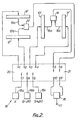
- An embodiment of an antenna unit of the invention comprises first and second dipole antennas 8' and 9' respectively, which are disposed opposite each other and third and fourth dipole antennas 10' and 11' respectively, which are disposed opposite to each other.
- a signal mixer 12 is connected by two coaxial cables 13a and 13b of equal length to the first and second antennas 8' and 9' and a further signal mixer 14 is connected by two coaxial cables 15a and 15b of equal length to the third and fourth antennas 10' and 11'.
- a further signal mixer 16 is provided for mixing signals from the mixers 12 and 14 and produces a composite output signal from its output terminal 17.
- Atuning control means 18 is provided for controlling the variation of the tuning circuits for the first to fourth antenna 8' to 11'.
- the tuning control means 18 is provided with a control signal source 19a for providing a control signal V, a second control signal source 19b for providing a control signal V-AV, and a third signal source 19c for providing a control signal V+AV.
- a changeover control unit 20 is provided for supplying the control signals fed to input terminals 7, 8 and 9 from the control signal sources 19a to 19c respectively in various combinations to the output terminals 1, 2, 3 and 4 of the unit 20 which are connected to the antenna elements 8' to 11' respectively.
- the changeover control unit 20 includes a changeover control section 21 for controlling connection between output terminals 10 and 11 connected to the signal mixer 16 and input terminals 5 and 6 which are connected to the mixers 14 and 12 respectively.
- the antenna elements 8' to 11' may alternatively be disposed as shown in Figure 3, in which the elements 8' and 9' of one dipole antenna are still perpendicular to the elements 10' and 11' of the other dipole antenna though they are disposed between the elements 10' and 11'.
- Each dipole antenna in Figure 2 or 3 is constructed as shown in Figure 4.
- Shortened antenna elements 22 and 22' having evenly distributed inductance are made from metallic foil, metallic wire, or conductive foil on a printed circuit board, using a metal having a low electrical resistance value, such as copper, aluminium or iron.
- the elements 22 and 22' are formed into a sinuous substantially square waveform pattern by having been bent a required number of times at a number of points, in the required direction. This square waveform pattern produces the necessary distributed inductance which is equivalent to providing a conventional element with a coil for cancelling the reactance of conventional elements as shown in Figures 1(a) and (b). Hence, the elements 22 and 22' need not use the conventional coils.
- elements having a wide surface area and of foil-like or thin-tubular shape may be used thereby making it possible to considerably reduce losses.
- the elements 22 and 22' are tunable over a limited range of frequencies by connection to a variable reactance circuit.
- the variable reactance circuit can employ a parallel resonance circuit or a series resonance circuit.
- a resonant circuit when in use, has a large reactance value at frequencies on either side of the resonance frequency fr, as shown in Figure 5, so that fr may be set to enable control of reactance components of the elements 22 and 22'.
- the antenna element pattern is so designed that the impedance of the elements 22 and 22' when fr is set at frequency f 1 to f 2 to f 3 describes a curve A in Figure 6.
- the elements 22 and 22' as shown in Figure 4 are connected to respective parallel resonance circuits each comprising a coil 23, 23'; a variable capacitor 24, 24' and capacitor 25, 25'.
- the resonance frequency changes from f 1 to f 2 to f 3
- the impedance forms a curve B as shown in Figure 6.
- a capacitor 30 of a suitable value is connected between the input terminals 29 and 29', the impedance describes a curve as shown at C in Figure 6 to obtain resonance at frequency f 2 .
- the variable reactance circuit may use series resonance circuits for obtaining the same tuning as the above.
- the capacitor value may of course be fixed to change the inductance value of the coil.
- Bias voltage for the variable capacitance diodes used as the variable capacitors 24, 24' in Figure 4 is supplied through high-frequency blocking resistances 28, 28' supplied from a d.c. voltage power supply 26 via the slider of a potentiometer 27.
- the capacitors 24, 24' are grounded at the other ends through high resistances 31, 31'.
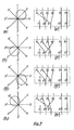
- the directivity characteristics of the antenna unit are controlled in a number of ways as shown in Figures 7(a) to (k) by changing over the changeover control unit 20 and control section 21.
- a matching resistance R is interposed between ground and either the terminal 10 or terminal 11 and the change over control unit 20 is changed to give four directivity characteristics.
- the changeover control unit 20 and control section 21 are changed over as shown in Figures 7(e) to (h) so as to enable an additional four ways of directional control of directivity characteristics.
- the directivity characteristic is directionally controllable in eight ways.
- the changeover control unit 20 and control section 21 can be operated so that the directivity characteristic forms the shape of a figure “8" or " 00 " as shown in Figures 7(i) and (j) respectively.
- the changeover control unit 20 and control section 21 are changed over as shown in Figure 7(k) to form a nearly omnidirectional antenna characteristic.
- FIG 8 is a block diagram of the receiving system of the invention, in which reference numeral 32 designates the antenna unit shown in Figure 2, including the antenna elements 8' to 11' with associated circuitry; the reference numeral 34 represents the control unit 20 and control section 21 with mixer 16; and the reference numeral 35 represents the tuning control 18 including the control signal sources 19a to 19c.
- the output terminal 17 of the mixer 16 within the changeover control unit 34 provides the output from the antenna unit 32 and is connected to an antenna terminal of a receiver 37 by a coaxial cable 36a, for feeding received signals to the receiver 37.
- Station-selection of receiver 37 is controlled by an output signal from a station-selection controller 51.
- the receiver 37 and antenna unit 32 are tuned to the desired frequency by means of a tuning control voltage V supplied to the antenna unit 32 by tuning control line 36b.
- An intermediate-frequency signal picked up from a wide dynamic range portion of an intermediate-frequency amplifier within the receiver 37 is supplied to an intermediate-frequency buffer amplifier 38 for amplification to the required level, and is further supplied to a multipath detector 39 which converts the multipath influence included in the amplifier intermediate frequency signal to an analog d.c. signal which is supplied to an analog d.c. signal which is supplied to an analog-digital converter 40 (hereinafter referred to as A/D converter) and converted into a digital signal.
- A/D converter analog-digital converter
- Directivity control of antenna unit 32 is carried out by a changeover control signal from a controller 42 supplied with a clock signal from a clock signal generator 41.
- the clock signal from clock signal generator 41 is also fed to a rotation detector 43 which detects the direction and angle of rotation of direction of the pattern of antenna unit 32.
- the output of rotation detector 43 controls the condition of a changeover switch 44 so that one input terminal 45a of the switch 44 is connected to an output terminal 45b of the switch 44 until the antenna unit ends its rotation. Then, after the rotation to the required angle, the changeover switch 44 is controlled to connect the other input terminal 45c of the output terminal 45b.
- a digital output signal from the A/D converter 40 is supplied to one input terminal 47a of a comparator 46 and a first latch 48, which temporarily stores the signal therein.
- the output from the first latch 48 is supplied to the other input terminal 47b of the comparator 46.
- the output which is also supplied to the first latch 48 outputs a digital signal "1" from its output 47c.
- This output is fed to one input of a second latch 49 which temporarily stores a changeover control signal from the rotation controller 42 in response to the digital signal "1" for application to the input terminal 45c of the changeover switch from an output terminal 50.
- the changeover switch 44 has its input terminal 45a connected to its output terminal 45b until the antenna unit 37 is directed at a required angle, whereupon its input terminal 45c is connected to the output terminal 45b. Hence, after rotation to the required angle, the directivity changeover controller 34 is supplied with the changeover signal temporarily stored in the second latch 49 to set the antenna unit 32 in the direction determined by the changeover signal.
- the digital comparator 46 and the first latch 48 function to sequentially compare the digital signal fed into the input terminal 47a with the digital signal fed to the input terminal 47b and, prior to the comparison, temporarily store in the first latch 48 the smaller of the two signals resulting in that the first latch 48 stores the smaller digital signal while the directivity of antenna 32 is being altered. Simultaneously, a digital signal "1" is present at the comparison output terminal 47c of the digital comparator 46 when the smaller digital signal is supplied to the input terminal 47a. Consequently, the second latch 49 stores the rotation control signal when the smaller digital signal is fed into the input terminal 47a of the digital comparator 46. As a result, the antenna unit 32 is automatically set to orient its directivity in the direction for minimizing the amount of multipath interference in input signal fed to the antenna terminal of the receiver 37.
- the directivity of the antenna unit and the rotation control signal supplied to the changeover control unit 34 are previously set in the appropriate conditions to correspond to each of the independent combinations as shown in Figure 7.
- the rotation control signal employs a simple relay switch for switching the combination of terminals 1 to 4 and 7 to 9 of the changeover control unit 20 and coaxial relay switches for switching the terminals 5, 6 and 10, 11 and the position of the matching resistance R of the control section 21.
- Receiver 37 may either use a digital control station-selection receiver having a closed loop block system using a PLL synthesizer, or have an open loop block system using a D/A converter.
- An electronic tuning receiver using d.c. voltages as the station-selection control signals, or a variable capacitor system receiver outputting a d.c. voltage signal changed in accordance with the required rotary angle, is of course applicable. Needless to say, it is of advantage if each unit is reset at every station-selection changeover operated by the station selection controller 51, so that the clock generator 41 may generate a clock pulse.
- the multipath detector 39 detects the amplitude modulation component by multipath interference of the intermediate-frequency signal, for example, in a level, unlimited signal, thereby detecting it as a d.c. voltage output.
- Figure 10 shows a modified embodiment of the antenna unit as shown in Figure 2 and the same reference numerals have been used to designate the same components as shown in Figure 2. For simplicity their operation is not repeated.
- Figure 10 differs from Figure 2 in that a tuning control means 69 is provided for variably controlling the tuning circuits of the elements 8' to 11'.
- first and second phase shifters 62 and 63 are interposed at desired equally spaced intermediate positions along the coaxial cables 13a and 13b between the elements 8', 9' and the mixer 12 while third and fourth phase shifters 64 and 65 are interposed at desired equally spaced intermediate positions along the coaxial cables 15a, 15b between the elements 10', 11' and the mixer 14.
- Control means 18 for variably controlling the first to fourth phase shifters 62 to 65 including a first control signal source 66a for generating a digital signal "0" and a second signal source 66b for generating a digital signal "1" are provided and the changeover control unit 20 provides a combination of control signals from the output of the first and second control signal sources 66a and 66b constituting the control means 18 for reception by the first to fourth phase shifters 62, 63, 64 and 65.
- the terminal 1 of the changeover control unit 20 is connected to the first phase shifter 62; the terminal 2 with the second phase shifter 63; the terminal 3 with the third phase shifter 64; the terminal 4 with the fourth phase shifter 65; the terminal 7 with the first control signal source 66a, and the terminal 8 with the control signal source 66b.
- the changeover control section 21 is connected as in Figure 2.
- the first, second, third and fourth phase shifters 62, 63, 64 and 65 in Figure 10 have for example a zero phase shift when the changeover control unit 20 gives a digital output signal "0" from the first control signal source 66a and a phase shift - ⁇ equal to space propagation phase shift of the radio wave in the space d between the opposite facing elements of each dipole when the digital output signal "1" is present from the second control signal source 66b.
- the first to fourth elements 8' to 11' are arranged as shown in Figure 11 where the elements 8' and 9' are between the elements 10' and 11'.
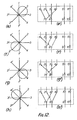
- the changeover unit 20 and section 21 are changed over as shown in Figures 12a' to p', so that the directivity characteristic is directionally controllable in sixteen ways as shown in Figures 12a to p, respectively.
- a matching resistance R is interposed between ground and either the terminal 9 or 10 in Figures 12a' to d' and i' to I' where the directivity characteristic forms the figure "8" in two ways as shown in Figures 12i to I.
- the changeover control means unit 20 is set as shown in Figures 12m' to p' the directivity characteristics are nearly omni-directional.
- FIG. 13 Another modified embodiment of the antenna unit is shown in Figure 13, and the same reference numerals are used to designate the same components as shown in Figure 2.
- a first, radiating dipole antenna element 70 and first and second dipole antenna elements 71, 72 serving as directors and/or reflectors are arranged side by side.
- a second radiating dipole antenna element 73 and first and second dipole antenna elements 74, 75 serving as directors and/or further reflectors are arranged side by side, but at right angles to the elements 70, 71 and 72.
- the changeover control unit 20 is provided with ten terminals but now the terminal 1 is connected to both the elements 70 and 73; the terminal 2 is connected to the antenna element 71; the terminal 3 is connected to the antenna element 72; the terminal 4 is connected to the antenna element 74; the terminal 5 is connected to the antenna element 75; the terminal 8 is connected to a first control signal source 17a; the terminal 9 is connected to a second control signal source 17b; and the terminal 10 is connected to a third control signal source 17c.
- the changeover control section 21 has its terminal 6 connected to the antenna element 73; its terminal 7 connected to the antenna element 70, and its terminals 11 and 12 to the mixer 16.
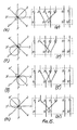
- the changeover control unit 20 and the control section 21 are set as shown in Figures 15a' to k' to enable eleven ways of directional control of the directivity characteristic as shown in Figures 15a to k.
- a matching resistance R is interposed between ground and either the terminal 11 or 12 in the case of Figures 15a' to d' and i' and k'.
- the directivity characteristic of a three-element Yagi antenna is controllable in eight ways as shown in Figures 15a to h.
- the antenna unit is directionally controllable in two ways when its directivity characteristic is in the shape of the figure "8" as shown in Figures 15i to j.
- the changeover control unit 20 and the changeover control section 21 are set as shown in Figure 15k' the antenna becomes almost omnidirectional as shown in Figure 15k.
- the six elements are arranged as shown in Figure 14, so that the elements 70 and 73 form a cross in the centre of a box whose opposite walls are formed by the elements of the remaining dipoles.
- Figures 16 to 24 show an embodiment of an antenna unit according to the invention, which is provided with at least two antenna elements arranged parallel to each other at a set distance.
- Figure 16 shows the antenna unit in which reference numerals 103 and 104 designate first and second dipole antenna elements.
- a signal mixer 105 is connected to the antenna elements 103 and 105 by equal length coaxial cables 106a and 106b.
- An output terminal 107 of the signal mixer 105 is connected to a receiver 108 which in turn is connected to a multipath detector 109 which converts the detected multipath interference included in the intermediate-frequency picked up from a wide dynamic range portion by an intermediate-frequency buffer and changed into a d.c. component to be supplied to a comparator 110 for comparison with a reference signal generated by a reference signal generator 111. If the multipath detection signal is higher in level than the reference signal level, the comparator 110 delivers a "1" from its output. When the multipath detection signal is lower than the reference level, the comparator 110 delivers a "0" from the output.
- the reference signal is previously set at a level equivalent to the multipath D/U (desired/unwanted) ratio under the detection limit where the multipath influence is not detected in the demodulated output from the receiver 108.
- the output signal from the comparator 110 is supplied as a control signal to a sweep controller 112, the output signal AV therefrom being supplied to the signal adders 113 and 114.
- the adders 113 and 114 receive as well as the signal AV from the sweep controller 112 a tuning control signal V from a tuning controller 115, polarity controllers 116 and 117 determining whether the adders serve to add or subtract, i.e.
- the output voltage is V+AV when adding, and V ⁇ V when subtracting, and is supplied as the tuning signals V, or V 2 for the dipole antenna elements 103 and 104 respectively.
- the input signal to the sweep controller 112 is "1" its output operates in the direction of increasing sweep, and when the input signal is "0" its output operates in the direction of decreasing sweep.
- the phase characteristics for tuning the elements 103 and 104 are shown in Figure 18.
- the adders output a control signal V+AV, larger than control signal V, the phase leads and, when they output a control signal V-AV, smaller than the control signal V, the phase lags.
- the antenna elements 103 and 104 have a phase difference of -2 ⁇ e when viewed from the signal mixer 105 as shown in Figure 19a, thus making the directivity characteristic have the maximum sensitivity axis at the B side as shown in Figure 19b.
- a phase difference feed type antenna unit is provided.
- antenna elements 103 and 104 have a phase difference of -2 ⁇ e when viewed from the signal mixer 105 as shown in Figure 20a.
- the directivity characteristic has the maximum sensitivity axis at the A side as shown in Figure 20b.
- a phased array antenna device is provided.
- the relative performance gain characteristics has a relationship as shown in Figure 22, and in particular Figure 22c with respect to Figure 19, Figure 23a with respect to Figure 20, and Figure 23e with respect to Figure 21.
- a back gain on the A side becomes zero so that the so-called front-to-back ratio becomes infinite, but a front gain on the B side becomes lower.
- the back gain on the B side becomes zero when sub-control signal AV is AV", and the so-called front-to-back ratio becomes infinite, but the front gain on the A side becomes lower.
- ⁇ V ⁇ 0 hereinafter referred to as ⁇ V'
- the front-to-back ratio and forward gain are present in the intermediate range of the relative performance gain characteristic.
- the maximum sensitivity axes lies on the A and B sides respectively, whereby the front to back ratio is 1 and has a performance gain which is the highest in comparison with other cases.
- Figure 22 represent the envelopes for the gain values on the A and B sides, and the corresponding characteristics are shown in Figures 23a and b, where Figures 23 shows the characteristics for Figures 22a to c, and Figure 22b shows those for Figures 22c to e.
- Additive polarity controllers 116 and 117 are set so that when the desired signal D comes from the A side and the unwanted signal U giving the multipath interference comes from the B side of the directivity characteristic as shown in Figure 25a, V, is made greater than V 2 , that is the additive polarity controllers 116 and 117 are set to be plus addition and a minus addition respectively.
- the additive polarities are set to the opposite sign.
- the antenna unit's directivity is automatically set so that the multipath D/U supplied to the receiver 108 becomes under the previously set detection limit.
- the directivity is automatically set to make the multipath D/U maximum under the detection limit and the desired signal D a maximum, the directivity is set in the best receiving position relative to the distribution of radio waves.
- the control signal V is advantageously variably controlled by the tuning controller 115 so that the tuning frequency of the antenna unit may be desirably variably controlled.
- Figures 25 to 28 show an embodiment of a receiving device according to the invention having at least two antenna elements disposed parallel to each other at a desired distance d.
- First and second variable phase shifters 123 and 124 are interposed at desired positions intermediate the ends of the coaxial cables 106a and 106b.
- a tuning controller 125 is provided for variably controlling the elements 103 and 104.
- a relationship between the phase shifts amounts ⁇ 1 and ⁇ 2 and the phase shift space propagation delay ⁇ d of the radio wave are shown in the directivity characteristic of the antenna unit in Figure 26.
- the characteristic is the shape of the figure "8" as shown in Figure 26c and the maximum sensitivity axes lie on both the A and B sides and its performance gain is the highest in comparison with other cases.
- the directivity characteristic becomes unilateral and if
- ⁇ d.
- the characteristic is as shown in Figure 26a, in which the maximum sensitivity axis and the front gain lie on the B side and the back gain which lies on the A side becomes zero so that the front-to-back ratio becomes infinite, but the performance gain degrades.
- ⁇ d the characteristic is as shown in Figure 26b, in which the front-to-back ratio and performance gain are in the intermediate range.
- the directivity characteristic is as shown in Figure 28a, and the additive polarity controllers 116 and 117 are set in a minus addition and a plus addition respectively so LP1 ⁇ LP2-
- the directivity characteristics are as shown in Figure 28b and the additive polarity controllers 116 and 117 are changed around. Thereafter, the antenna directivity is automatically set so that the multipath D/U fed into the receiver 126 is under the previously set detection limit.
- the multipath detector 127 can use a detecting system which detects the amplitude modulation component by the multipath interference in intermediate frequency in a level zone free from a limiter and detects a d.c. voltage output.
- FIG 29 is a block diagram of an embodiment of the antenna unit of the invention, in which the same reference numerals have been used to designate the same components as in the unit shown in Figure 8.
- the output from the station-selection control 51 is simultaneously supplied to the receiver 37, a comparator 142 and to the input terminal 144a of a memory unit 143.
- the output from the memory unit 143 is supplied from the output terminal 144c to the other input of the comparator 142.
- the comparator output signal supplied to a memory readout control unit 145 stops the former transfer operation of the stored content in the memory unit 143.
- Another input terminal 144b of the memory 144 receives a control output from a manual changeover control unit 146 and in accordance with the output signal from the readout control unit 145 is then supplied to the input terminal of the line changeover unit 144.
- the changeover control output from the manual changeover unit 146 is supplied into the other input terminal of the line changeover unit 144.
- Both the station-selection control output and the line changeover control output can be stored simultaneously at the same address in the memory unit 143 when a memory mode change- over control unit 148 is set in the write-in mode and the memory instruction output from the memory instruction unit 149 are supplied to the memory unit 143.
- the memory mode changeover control unit 148 is switched to the readout mode, the two kinds of control signals are supplied from the readout output terminals 144c and 144d.
- a desired combination of a plurality of different codes of the station-selection output signal and the optimum antenna direction changeover control signal are stored in the memory unit 143. Thereafter, only the station-selection control signal set by the station-selection control unit 51 can simultaneously set the antenna unit electronically in the optimum direction.
- the transfer of the stored content in the memory unit 143 is carried out in a ring shift type of sequentially shifting from the write-in input terminals 144a, 144b to the readout output terminals 144c and 144b and of returning to the write-in input terminals 144a and 144b.
- the antenna element unit 32 in Figure 29 may use the modified embodiment of the antenna element in Figures 10 to 12, or alternatively the modified embodiment of the same as shown in Figures 13 to 15.
- Figure 30 shows an embodiment of the antenna device according to the invention, which is so constituted that four antenna elements may either be disposed as shown in Figure 2 or 3.
- the antenna system uses some of the components shown in the antenna system shown in Figure 8 and these will have the same reference numerals.
- the preferred embodiment of the invention allows the tuning control signal of each antenna element, the directive signal controlling the directivity of the antenna unit, and the receiving or transmitting signal to communicate with each other by a coaxial cable connecting the antenna unit with the receiver or transmitter.
- the terminal 17 of the mixer 16 within the changeover control unit 34 is connected to the input terminal for the antenna unit 32 and to the terminal 157 of the receiver 156 by a coaxial cable 155.
- the receiver 156 is provided with a pretuning circuit comprising a coil 158, a voltage control variable reactance element 159 and a condenser 160, and is connected to the terminal 157 through a capacitor 161.
- the tuning control signal V from a tuning controller 163 provided within the receiver 156 is connected to the terminal 157 by a choke coil 162.
- the tuning control signal V is supplied to the voltage control variable reactance element 159 via a high frequency blocking resistance 164.
- the tuning control signal V is supplied through the coaxial cable 155 and is supplied to the change- over control signal generator 35 via a low-pass filter 165.
- the required changeover signals V, V+AV and V-AV are changed over and supplied to the antenna element unit 33 via the changeover control unit 34.
- the antenna tuning frequency of the antenna element unit 32 and the tuning frequency of the receiver 156 become possible for tracking respectively, where the variable reactance element used for the antenna element unit 34 and that used for the receiver 156 are unified in kind.
- the directivity control of the antenna unit is carried out in such a manner that the directivity rotation control signal generated from the directivity rotation control signal generator 168 by means of a signal set by normal rotation directivity setter 166 or the reverse rotation directivity setter 167 is supplied to the terminal 157, then transmitted by the coaxial cable 155, discri- mintated and detected by the normal rotation control signal detector 169 or the reverse rotation control signal detector 170, and supplied into a counter 171, the count output being converted by the signal converter 172 and supplied into the changeover control unit 34 through the change- over switch driver 173, thereby desirably changing over the changeover switch.
- the form of the directivity rotation control signal in a case of normal rotation control signal, can be distinguished in polarity direction by a positive polarity pulse signal, and, in a case of reverse rotation control signal, by a negative polarity pulse signal.
- Another form of the directivity rotation control signal in a case of normal rotation control signal, can be distinguished by a pulse signal frequency of relatively high frequency pulse signal, and, in a case of reverse rotation control signal, for relatively low frequency pulse signal.
- the above pulse signal itself or its high frequency does not affect the receiving frequency zone of the receiver 156.
- Normal or reverse rotation control signal generator 169 or 170 when the directivity rotation control signal is distinguished directionally by the polarity direction of the pulse signal, detects each polarity, discriminates passing or blocking the pulse signal, and supplies the pulse signal into the control signal counter 171 to be added or subtracted.
- the directional distinction is due to pulse signal frequency, the inherent frequency of each pulse signal is detected to discriminate passing or blocking the pulse signal and then similarly processed.
- a relation between the pulse signal of the directivity rotation control signal and the antenna direction changeover of the antenna element unit 32 allows rotation at one degree of the minimum resolution angle at the direction changeover to correspond with respect to one bit of the pulse signal.
- said pulse signal frequency may be desirably variable, or a suitable frequency divider may be provided at the front of control signal counter 170.
- the control signal counter 171 may be a usual pulse counter having addition mode signal input terminal 171a and subtraction mode signal input terminal 171b.
- this antenna system of the invention can fulfill similar functional effect as a transmitter system.
- this invention can overlap-transmit three kinds of receiving or transmitting, directivity rotation control signal, and tuning tracking the control signal without affecting each other by using a coaxial cable connecting the antenna unit with the receiver or transmitter. Therefore, one coaxial cable is sufficient for a connecting cable necessary to perform the directivity rotation remote control of the antenna unit when the antenna system and receiver or transmitter system are separated by a long distance, thereby considerably reducing the cost to install the cable in comparison with the conventional one. Furthermore, the device of the optionally variable directivity rotation direction and the rotation speed can be materialized with simple circuitry and parts, thereby enabling reduction of consumption power and a continuous operation for a long time.
Landscapes
- Variable-Direction Aerials And Aerial Arrays (AREA)
Claims (7)
Applications Claiming Priority (4)
| Application Number | Priority Date | Filing Date | Title |
|---|---|---|---|
| JP86785/79 | 1979-07-09 | ||
| JP8678579A JPS5610742A (en) | 1979-07-09 | 1979-07-09 | Receiving device |
| JP8678879A JPS5610710A (en) | 1979-07-09 | 1979-07-09 | Receiving device |
| JP86788/79 | 1979-07-09 |
Publications (3)
| Publication Number | Publication Date |
|---|---|
| EP0022656A2 EP0022656A2 (de) | 1981-01-21 |
| EP0022656A3 EP0022656A3 (en) | 1981-03-25 |
| EP0022656B1 true EP0022656B1 (de) | 1985-05-02 |
Family
ID=26427873
Family Applications (1)
| Application Number | Title | Priority Date | Filing Date |
|---|---|---|---|
| EP80302320A Expired EP0022656B1 (de) | 1979-07-09 | 1980-07-09 | Antennesystem mit steuerbarem Strahlungsdiagramm |
Country Status (3)
| Country | Link |
|---|---|
| US (1) | US4334230A (de) |
| EP (1) | EP0022656B1 (de) |
| DE (1) | DE3070576D1 (de) |
Cited By (2)
| Publication number | Priority date | Publication date | Assignee | Title |
|---|---|---|---|---|
| TWI682585B (zh) * | 2018-10-04 | 2020-01-11 | 和碩聯合科技股份有限公司 | 天線裝置 |
| US10840610B2 (en) | 2018-02-07 | 2020-11-17 | Pegatron Corporation | Antenna device |
Families Citing this family (19)
| Publication number | Priority date | Publication date | Assignee | Title |
|---|---|---|---|---|
| US4851830A (en) * | 1987-10-20 | 1989-07-25 | Telefind Corp. | Paging receiver with continuously tunable antenna |
| US5136719A (en) * | 1988-12-05 | 1992-08-04 | Seiko Corp. | Automatic antenna tubing method and apparatus |
| US5303240A (en) * | 1991-07-08 | 1994-04-12 | Motorola, Inc. | Telecommunications system using directional antennas |
| US5818385A (en) * | 1994-06-10 | 1998-10-06 | Bartholomew; Darin E. | Antenna system and method |
| JP2783222B2 (ja) * | 1995-11-13 | 1998-08-06 | 日本電気株式会社 | 移動通信システムのアンテナ利得制御装置 |
| JP2003243922A (ja) * | 2002-02-15 | 2003-08-29 | Toyota Central Res & Dev Lab Inc | アンテナ装置 |
| JP4088140B2 (ja) * | 2002-11-21 | 2008-05-21 | Dxアンテナ株式会社 | アンテナシステム |
| EP1530255A1 (de) * | 2003-11-07 | 2005-05-11 | Matsushita Electric Industrial Co., Ltd. | Adaptive Antennenanordnung mit mehreren Paaren bidirektionaler Antennen |
| JP4466827B2 (ja) * | 2003-12-11 | 2010-05-26 | 日本電気株式会社 | アンテナ装置及び無線通信装置 |
| JP4353004B2 (ja) * | 2004-06-25 | 2009-10-28 | 船井電機株式会社 | 放送受信機 |
| JP4270278B2 (ja) * | 2004-09-03 | 2009-05-27 | 株式会社村田製作所 | アンテナ装置 |
| US7813449B2 (en) * | 2005-07-14 | 2010-10-12 | Radio Shack, Corporation | Remotely controlled antenna and method |
| JP4879726B2 (ja) * | 2006-12-28 | 2012-02-22 | Dxアンテナ株式会社 | アンテナ装置 |
| US20090280751A1 (en) * | 2008-05-07 | 2009-11-12 | Ahmadreza Rofougaran | Method And System For On-Demand Beamforming |
| JP2011091682A (ja) * | 2009-10-23 | 2011-05-06 | Murata Mfg Co Ltd | 無線信号受信装置 |
| US10276941B2 (en) * | 2014-01-20 | 2019-04-30 | Qorvo Us, Inc. | Multiple-input multiple-output RF antenna architectures |
| GB2528839B (en) | 2014-07-25 | 2019-04-03 | Kathrein Werke Kg | Multiband antenna |
| WO2018082000A1 (zh) * | 2016-11-04 | 2018-05-11 | 深圳市大疆创新科技有限公司 | 无人机及天线组件 |
| EP4622000A1 (de) * | 2024-03-21 | 2025-09-24 | Siemens Aktiengesellschaft | Schaltbare breitbandantenne |
Family Cites Families (12)
| Publication number | Priority date | Publication date | Assignee | Title |
|---|---|---|---|---|
| US2761134A (en) * | 1952-01-18 | 1956-08-28 | Bendix Aviat Corp | Means for operating antennas |
| US3056961A (en) * | 1957-08-15 | 1962-10-02 | Post Office | Steerable directional random antenna array |
| US3209358A (en) * | 1962-09-24 | 1965-09-28 | Robert A Felsenheld | Electronically tunable antenna |
| US3996592A (en) * | 1965-02-04 | 1976-12-07 | Orion Industries, Inc. | Antenna with rotatable sensitivity pattern |
| US3670335A (en) * | 1967-06-08 | 1972-06-13 | Bell Telephone Labor Inc | Arrays with nulls steered independently of main beam |
| AU418988B2 (en) * | 1968-05-20 | 1971-11-17 | Improved transistorised antenna | |
| US3582953A (en) * | 1969-06-09 | 1971-06-01 | Aerojet General Co | Control circuit for setting phase shifters in scanned antenna array |
| US3981016A (en) * | 1974-03-06 | 1976-09-14 | Matsushita Electric Industrial Co., Ltd. | Antenna apparatus for detecting an optimum directivity |
| DE2634111A1 (de) * | 1976-07-29 | 1978-02-02 | Hans Heinrich Prof Dr Meinke | Antennenanlage zum gerichteten empfang einer elektromagnetischen welle |
| US4123759A (en) * | 1977-03-21 | 1978-10-31 | Microwave Associates, Inc. | Phased array antenna |
| US4193077A (en) * | 1977-10-11 | 1980-03-11 | Avnet, Inc. | Directional antenna system with end loaded crossed dipoles |
| US4213133A (en) * | 1977-11-10 | 1980-07-15 | Tokyo Shibaura Denki Kabushiki Kaisha | Linear antenna arrays |
-
1980
- 1980-07-03 US US06/165,940 patent/US4334230A/en not_active Expired - Lifetime
- 1980-07-09 DE DE8080302320T patent/DE3070576D1/de not_active Expired
- 1980-07-09 EP EP80302320A patent/EP0022656B1/de not_active Expired
Cited By (2)
| Publication number | Priority date | Publication date | Assignee | Title |
|---|---|---|---|---|
| US10840610B2 (en) | 2018-02-07 | 2020-11-17 | Pegatron Corporation | Antenna device |
| TWI682585B (zh) * | 2018-10-04 | 2020-01-11 | 和碩聯合科技股份有限公司 | 天線裝置 |
Also Published As
| Publication number | Publication date |
|---|---|
| EP0022656A2 (de) | 1981-01-21 |
| US4334230A (en) | 1982-06-08 |
| EP0022656A3 (en) | 1981-03-25 |
| DE3070576D1 (en) | 1985-06-05 |
Similar Documents
| Publication | Publication Date | Title |
|---|---|---|
| EP0022656B1 (de) | Antennesystem mit steuerbarem Strahlungsdiagramm | |
| US6933907B2 (en) | Variable directivity antenna and variable directivity antenna system using such antennas | |
| US6407719B1 (en) | Array antenna | |
| US4381566A (en) | Electronic tuning antenna system | |
| US5617102A (en) | Communications transceiver using an adaptive directional antenna | |
| US5450093A (en) | Center-fed multifilar helix antenna | |
| US7142162B2 (en) | Antenna structure and television receiver | |
| JP3029231B2 (ja) | 二重円形偏波temモードのスロットアレーアンテナ | |
| KR20070058009A (ko) | 비동조 배열 안테나 | |
| KR20100134541A (ko) | 차량에서 다이버시티 기능을 갖는 무선 수신용 안테나 | |
| US5521607A (en) | Bandswitched electrically short tactical monopole antenna system | |
| JPH0621711A (ja) | 自動車用アンテナ装置 | |
| US5274388A (en) | Antenna device | |
| US20070087787A1 (en) | Antenna and signal-receiving apparatus using the same | |
| US4477812A (en) | Signal acquisition and tracking system | |
| US2838755A (en) | Cabinet antenna system | |
| JP4509870B2 (ja) | アンテナ装置 | |
| US2187015A (en) | Directional aerial system | |
| US5694140A (en) | Non-squinting mast antenna and closed loop control thereof | |
| US2941206A (en) | Multi-band radio frequency antennas | |
| JP2611883B2 (ja) | 衛星通信用移動局アンテナ | |
| US4947182A (en) | Method of feeding electromagnetic power from an antenna element | |
| JP3374750B2 (ja) | 移動通信用基地局アンテナ | |
| RU2138908C1 (ru) | Способ и устройство для приема радио- и телевизионного сигнала | |
| JP2629219B2 (ja) | 衛星放送用のダイバシティ受信装置 |
Legal Events
| Date | Code | Title | Description |
|---|---|---|---|
| PUAI | Public reference made under article 153(3) epc to a published international application that has entered the european phase |
Free format text: ORIGINAL CODE: 0009012 |
|
| PUAL | Search report despatched |
Free format text: ORIGINAL CODE: 0009013 |
|
| AK | Designated contracting states |
Designated state(s): DE FR GB |
|
| AK | Designated contracting states |
Designated state(s): DE FR GB |
|
| 17P | Request for examination filed |
Effective date: 19810907 |
|
| GRAA | (expected) grant |
Free format text: ORIGINAL CODE: 0009210 |
|
| AK | Designated contracting states |
Designated state(s): DE FR GB |
|
| REF | Corresponds to: |
Ref document number: 3070576 Country of ref document: DE Date of ref document: 19850605 |
|
| ET | Fr: translation filed | ||
| PLBE | No opposition filed within time limit |
Free format text: ORIGINAL CODE: 0009261 |
|
| STAA | Information on the status of an ep patent application or granted ep patent |
Free format text: STATUS: NO OPPOSITION FILED WITHIN TIME LIMIT |
|
| 26N | No opposition filed | ||
| PGFP | Annual fee paid to national office [announced via postgrant information from national office to epo] |
Ref country code: GB Payment date: 19910701 Year of fee payment: 12 |
|
| PGFP | Annual fee paid to national office [announced via postgrant information from national office to epo] |
Ref country code: DE Payment date: 19910830 Year of fee payment: 12 |
|
| PG25 | Lapsed in a contracting state [announced via postgrant information from national office to epo] |
Ref country code: GB Effective date: 19920709 |
|
| GBPC | Gb: european patent ceased through non-payment of renewal fee |
Effective date: 19920709 |
|
| PG25 | Lapsed in a contracting state [announced via postgrant information from national office to epo] |
Ref country code: DE Effective date: 19930401 |
|
| PGFP | Annual fee paid to national office [announced via postgrant information from national office to epo] |
Ref country code: FR Payment date: 19970709 Year of fee payment: 18 |
|
| PG25 | Lapsed in a contracting state [announced via postgrant information from national office to epo] |
Ref country code: FR Free format text: LAPSE BECAUSE OF NON-PAYMENT OF DUE FEES Effective date: 19990331 |
|
| REG | Reference to a national code |
Ref country code: FR Ref legal event code: ST |