EP0022740A2 - Reifenwandschutzschild - Google Patents
Reifenwandschutzschild Download PDFInfo
- Publication number
- EP0022740A2 EP0022740A2 EP80630023A EP80630023A EP0022740A2 EP 0022740 A2 EP0022740 A2 EP 0022740A2 EP 80630023 A EP80630023 A EP 80630023A EP 80630023 A EP80630023 A EP 80630023A EP 0022740 A2 EP0022740 A2 EP 0022740A2
- Authority
- EP
- European Patent Office
- Prior art keywords
- shield
- rim
- tire
- flange
- assembly
- Prior art date
- Legal status (The legal status is an assumption and is not a legal conclusion. Google has not performed a legal analysis and makes no representation as to the accuracy of the status listed.)
- Granted
Links
Images
Classifications
-
- B—PERFORMING OPERATIONS; TRANSPORTING
- B60—VEHICLES IN GENERAL
- B60S—SERVICING, CLEANING, REPAIRING, SUPPORTING, LIFTING, OR MANOEUVRING OF VEHICLES, NOT OTHERWISE PROVIDED FOR
- B60S1/00—Cleaning of vehicles
- B60S1/62—Other vehicle fittings for cleaning
- B60S1/66—Other vehicle fittings for cleaning for cleaning vehicle exterior
- B60S1/68—Other vehicle fittings for cleaning for cleaning vehicle exterior for freeing wheels or tyres from foreign matter, e.g. wheel scrapers
-
- B—PERFORMING OPERATIONS; TRANSPORTING
- B60—VEHICLES IN GENERAL
- B60B—VEHICLE WHEELS; CASTORS; AXLES FOR WHEELS OR CASTORS; INCREASING WHEEL ADHESION
- B60B7/00—Wheel cover discs, rings, or the like, for ornamenting, protecting, venting, or obscuring, wholly or in part, the wheel body, rim, hub, or tyre sidewall, e.g. wheel cover discs, wheel cover discs with cooling fins
- B60B7/01—Rings specially adapted for covering only the wheel rim or the tyre sidewall, e.g. removable tyre sidewall trim rings
-
- Y—GENERAL TAGGING OF NEW TECHNOLOGICAL DEVELOPMENTS; GENERAL TAGGING OF CROSS-SECTIONAL TECHNOLOGIES SPANNING OVER SEVERAL SECTIONS OF THE IPC; TECHNICAL SUBJECTS COVERED BY FORMER USPC CROSS-REFERENCE ART COLLECTIONS [XRACs] AND DIGESTS
- Y10—TECHNICAL SUBJECTS COVERED BY FORMER USPC
- Y10S—TECHNICAL SUBJECTS COVERED BY FORMER USPC CROSS-REFERENCE ART COLLECTIONS [XRACs] AND DIGESTS
- Y10S152/00—Resilient tires and wheels
- Y10S152/01—Pebble ejectors
-
- Y—GENERAL TAGGING OF NEW TECHNOLOGICAL DEVELOPMENTS; GENERAL TAGGING OF CROSS-SECTIONAL TECHNOLOGIES SPANNING OVER SEVERAL SECTIONS OF THE IPC; TECHNICAL SUBJECTS COVERED BY FORMER USPC CROSS-REFERENCE ART COLLECTIONS [XRACs] AND DIGESTS
- Y10—TECHNICAL SUBJECTS COVERED BY FORMER USPC
- Y10T—TECHNICAL SUBJECTS COVERED BY FORMER US CLASSIFICATION
- Y10T152/00—Resilient tires and wheels
- Y10T152/10—Tires, resilient
- Y10T152/10018—Tires, resilient with splash guards
Definitions
- This invention relates to protection of the sidewalls of vehicle tires which operate off the road.
- the sidewalls are particularly vulnerable to damage from sharply pointed rocks or other material which the tire is likely to encounter as it rolls over rough terrain for which off-the-road type vehicles are designed to operate.
- the invention may be used with any tire; however, it is most useful with a tire whose service conditions are such as to cause failure of the tire through damage to the tire sidewalls from contact with external objects.
- the invention is particularly well suited to the protection of one or both of the lower or radially inner portion of the sidewalls of large off-the-road type tires and especially those of a design which includes a replaceable tread or traction belt, which are more vulnerable to sidewall damage due to their increased service life. It may be used in conjunction with an upper sidewall protection device, an example of which is shown in United States Patent No 4,030,530.
- the invention may be used with any tire for which protection is required.
- a resilient shield fastened adjacent the tread of a tire has been extended from its attachment point adjacent the tread of the tire to the tire rim flange where the shield was also secured.
- a sectional annular shield has been attached to the rim flange by means of a plurality of removable fasteners circumferentially spaced about the rim flange, the shield being retained between the rim flange and ring segments by the removable fastening means.
- An annular tire sidewall protection shield is removably attached to a tire rim.
- the tire rim includes a tire-supporting flange axially spaced of its centerplane.
- the tire rim terminates in a portion directed generally radially inwardly toward the axis of rotation of the rim.
- the terminal portion of the rim includes a plurality of generally axially directed apertures spaced apart about its circumference.
- An annular resilient shield axially engages said terminal portion of the rim.
- the radially inner portion of the shield is discontinuous to permit egress of debris from between the sidewall of a tire mounted on the rim and the shield.
- the radially inner portion of the shield may include a plurality of generally radially inwardly directed tabs.
- the shield near its radially inner portion of the shield may include a plurality of apertures.
- the shield extends radially outwardly of the axis of rotation of the tire rim from a radius corresponding to that of the terminal portion of the rim.
- the shield is interposed between an annular ring and the terminal portion of the rim.
- the ring includes a plurality of apertures extending generally in an axial direction therethrough.
- the apertures of the ring are spaced apart about the circumference of the ring.
- the apertures of the components are aligned and removable fastening means extend through the aligned apertures of the shield and ring in a generally axial direction to secure the shield and ring to the terminal portion of the rim.
- a spacer such as a plurality of blocks or a second annular ring is positioned between the terminal portion of the rim and the shield.
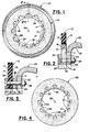
- an annular tire sidewall protection shield 12 is removably secured to the flange 21 of a tire rim 20.
- the shield 12 covers at least the radially innermost portion or lower sidewall portion of tire 10.
- the tire rim 20 includes a pair of tire supporting flanges (not illustrated) axially spaced from its centerplane.
- the centerplane (not illustrated) of the rim 20 is a plane perpendicularly intersecting the axis of rotation 60 of the rim and being located midway between the axially spaced tire supporting flanges of the rim.
- the flange 21 of tire rim 20 includes a terminal portion 22 directed generally radially inwardly toward the axis of rotation 60 of the rim 20.
- the terminal portion 22 of the rim flange 21 includes a plurality of generally axially directed apertures 24 spaced apart about its circumference for receipt of a plurality of generally axially extending fasteners (such as typified by bolt and nut 38).
- axially and related forms mean in a direction generally parallel to the axis of rotation of the respective shield, rim, tire or assembly of a shield and rim.
- the axis of rotation 59 of the shield 50 is shown in Figure 4.
- the shield 12 is positioned axially outboard of the terminal portion 22 of the rim flange 21.
- an item which is "axially inboard” of another is nearer to the centerplane of the respective tire rim or tire rim and protection shield assembly.
- an item which is "axially outboard” of another is farther away from the centerplane of the respective tire rim or tire rim and protection shield assembly.
- the shield 12 is an annular protective body of resilient sheet material for absorbing impact from rocks and other debris.
- the shield 12 may be formed of sections (not illustrated) for example, by cutting and piecing together slabs of elastomeric material to form a disc with its center removed.
- the shield 12 is circumferentially continuous to avoid the need for fasteners which may become broken or snagged during operation of the assembly in its normally harsh environment.
- the shield 12 may be formed of reinforced elastomeric material, for example, textile and/or wire reinforced rubber or a resilient plastic such as polyurethane.
- the shield 12 may be retained by frictional forces by compressing the shield between the terminal portion 22 of the rim flange and an annular ring 34 as illustrated in Figure 2.
- the shield may be fastened to the rim flange and interposed between a pair of annular rings (not illustrated), or between a plurality of spacer blocks 26 and an annular ring 34 as shown in Figure 3.
- the ring 34 and spacer blocks 26 are typically made of a metal such as steel.
- the shield 12 preferably includes a plurality of generally axially extending apertures 36 which are circumferentially spaced apart about its radially inner portion 14 in alignment with corresponding apertures (37,39) in the corresponding rings and spacers.
- the shield 12 extends radially outwardly of the axis of rotation of the tire rim 20 from a radius corresponding to that of the rim flange terminal portion 22.
- the maximum radial extent of the shield 12 is an amount greater than the radius of the tire 10 protected thereby at the point of maximum axial dimension of the tire.
- the radially inner portion 14 of. the shield 12 is discontinuous. These discontinuities 18 in the radially inner portion 14 of the shield 12 may include a plurality of circumferentially spaced apart radially inwardly directed projections or tabs 16 as shown in Figures 1-3.
- the shield 50 may include a plurality of apertures 52 circumferentially spaced apart near its radially innermost end 54. Apertures 52 are of a size greater than needed for passage of fastening means such as bolts 38 therethrough and preferably, are in addition to apertures 51 provided for passage of fastening means.
- the apertures 52 each have a perimeter formed of radially directed line segments joined by one or more circumferentially directed arcuate segments.
- the discontinuities may appear to be a series of circumferentially spaced polygons, circles or other geometric figures. What is important is that the discontinuities when the shield is installed form apertures (numeral 15 in Figure 1 or numeral 52 in Figure 4) to permit egress of the debris from between the shield and a tire sidewall protected thereby.
- the embodiment shown in Figure 4 can also be described as including a plurality of radially inwardly directed tabs 55 which are joined at their radially inward ends 56 by a plurality of circumferentially extending tie-bars 58 to define apertures 52.
- the shield 12 may be positioned so as to directly abut the rim flange terminal portion 22.
- the axially inboard surface 13 of the shield 12 is in contact with the axially outboard surface 11 of the rim flange terminal portion 22.
- annular ring 34 which directly abuts the shield 12.
- Annular ring 34, shield 12 and the rim flange terminal portion 22 each contain a plurality of circumferentially spaced generally axially directed apertures in alignment.
- a plurality of removable fasteners extend therethrough to bind the components together.
- the shield 12 is interposed between the rim flange 21 and annular ring 34.
- the fasteners are recessed or present a flush surface with ring 34 to prevent snagging of the assembly.
- a plurality of spacer blocks 26 may be positioned about the circumference of the rim flange terminal portion 22 so as to position the shield 12 in axially spaced relationship to the terminal portion 22 of the rim flange. Because the spacer blocks 26 are not continuous in the circumferential direction of the ring, there is created a plurality of radially directed holes or apertures at circumferentially spaced apart positions through which debris contained between the tire sidewall and the sidewall protection shield 12 can exit.
- the spacing means may be a radially slotted ring (not illustrated), separate blocks 26 or comprise a sack of ordinary flat washers (not illustrated).
- each spacer block 26 includes an aperture 39 passing therethrough in a generally axial direction for receipt of one of the fastening means 38.
- the use and function of spacer means such as blocks 26 are further described in co-pending Application No 057, 22 7 , of R J Olsen et al, entitled Tire Sidewall Protector Shield Assembly, and commonly assigned herewith, and filed on even date herewith.
- radially means in a direction which is towards or away from the axis of rotation of the respective shield, tire rim or the tire rim and protection shield assembly, the direction being within a radial plane of the respective shield, tire rim or tire rim and protection shield assembly.
- a "radial plane" of the respective shield, tire rim or the tire rim and protection shield assembly is one which passes through and contains the axis of rotation of the respective shield, tire rim or the tire rim and protection shield assembly.
- tire rim and protection shown and described includes a shield for one sidewall of a tire, it is understood that both sidewalls of a tire may be protected in like manner.
- the shield has been shown and described as being attached to a terminal portion of the flange of a single component rim. It is understood that when a multipiece rim is employed, one of the rim components may, of course, be formed so as to provide an equivalent mounting site for the protection shield.
Landscapes
- Engineering & Computer Science (AREA)
- Mechanical Engineering (AREA)
- Tires In General (AREA)
Applications Claiming Priority (2)
| Application Number | Priority Date | Filing Date | Title |
|---|---|---|---|
| US57780 | 1979-07-16 | ||
| US06/057,780 US4252169A (en) | 1979-07-16 | 1979-07-16 | Tire sidewall protection shield |
Publications (3)
| Publication Number | Publication Date |
|---|---|
| EP0022740A2 true EP0022740A2 (de) | 1981-01-21 |
| EP0022740A3 EP0022740A3 (en) | 1981-06-03 |
| EP0022740B1 EP0022740B1 (de) | 1984-02-15 |
Family
ID=22012726
Family Applications (1)
| Application Number | Title | Priority Date | Filing Date |
|---|---|---|---|
| EP80630023A Expired EP0022740B1 (de) | 1979-07-16 | 1980-07-04 | Reifenwandschutzschild |
Country Status (7)
| Country | Link |
|---|---|
| US (1) | US4252169A (de) |
| EP (1) | EP0022740B1 (de) |
| JP (1) | JPS5617707A (de) |
| BR (1) | BR8004212A (de) |
| CA (1) | CA1141638A (de) |
| DE (1) | DE3066581D1 (de) |
| ZA (1) | ZA803488B (de) |
Cited By (3)
| Publication number | Priority date | Publication date | Assignee | Title |
|---|---|---|---|---|
| AU580434B2 (en) * | 1985-08-12 | 1989-01-12 | Eric William Bede Connolly | Pneumatic tyre protector |
| GB2230495A (en) * | 1989-04-22 | 1990-10-24 | Joyce Wilson | Wheel cover |
| WO2002100659A3 (en) * | 2001-06-12 | 2003-06-05 | O Z S P A | A motor vehicle wheel with improved protective ring |
Families Citing this family (13)
| Publication number | Priority date | Publication date | Assignee | Title |
|---|---|---|---|---|
| US4790362A (en) * | 1985-01-25 | 1988-12-13 | Price Donald Rex | Tire shield device |
| US5435630A (en) * | 1994-04-26 | 1995-07-25 | Tucker; Roshawn | Tire rim and hubcap protector |
| USD418102S (en) * | 1998-06-01 | 1999-12-28 | Schehr Terry L | Conical wheel spray shield |
| US6494473B1 (en) * | 2000-04-04 | 2002-12-17 | Sossy Baghboian | Tire protector |
| US20070290548A1 (en) * | 2006-06-14 | 2007-12-20 | Lundy Larry L | Wheel Rim Protector |
| US8196625B1 (en) * | 2006-08-08 | 2012-06-12 | Brant Chenoweth | Supplemental tread tire bead lock |
| US20100066155A1 (en) * | 2008-06-13 | 2010-03-18 | Hutchinson, Sa | Tire protection device attachment systems |
| US7775605B2 (en) * | 2008-08-13 | 2010-08-17 | Douglas Technologies Group, Inc. | Vehicle wheel with rock guard |
| US20130340908A1 (en) * | 2012-06-21 | 2013-12-26 | Adam Wirth | Outer bead lock wheel |
| DE202013103113U1 (de) | 2013-07-12 | 2014-10-13 | Erlau Ag | Schildförmiges Flankenschutzelement und Schutzvorrichtung für einen Fahrzeugreifen |
| US9937747B2 (en) | 2013-07-30 | 2018-04-10 | Hutchinson S.A. | Elastomeric fastener system for wheel devices |
| JP6786927B2 (ja) * | 2016-07-28 | 2020-11-18 | 住友ゴム工業株式会社 | 空気入りタイヤ |
| US11021010B2 (en) | 2017-06-12 | 2021-06-01 | Argonics, Inc. | Shielding assembly for side of tire |
Family Cites Families (11)
| Publication number | Priority date | Publication date | Assignee | Title |
|---|---|---|---|---|
| US1867518A (en) * | 1932-07-12 | Mud guard for motor cars | ||
| US967806A (en) * | 1908-09-29 | 1910-08-16 | Herman F D Meyer | Tire-shield. |
| US1140778A (en) * | 1913-08-27 | 1915-05-25 | Walter D Trigalet | Tire construction. |
| US1235251A (en) * | 1915-03-06 | 1917-07-31 | Edward Danforth Self | Mud-guard for automobiles or other vehicles. |
| DK31403C (da) * | 1921-09-05 | 1923-03-12 | Vilhelm Niels Joseph Nymann | Stænkskærm til Automobiler og lignende. |
| DK34858C (da) * | 1924-02-22 | 1925-08-10 | Stolefabr Christiansen-Moeller | Stænkskærm. |
| US1905674A (en) * | 1930-08-29 | 1933-04-25 | Babbs Alfred James | Splash guard for motor vehicles |
| GB511056A (en) * | 1938-02-12 | 1939-08-14 | William Henry Lambert | Improvements in protectors for the walls of pneumatic tyres |
| US3187797A (en) * | 1962-07-11 | 1965-06-08 | Dunlop Rubber Co | Pneumatic tires |
| US3135559A (en) * | 1962-11-05 | 1964-06-02 | Gen Motors Corp | Wheel mounted stone ejector |
| WO1979000425A1 (en) * | 1977-12-23 | 1979-07-12 | Caterpillar Tractor Co | Tire sidewall protector for multi-piece rim wheels |
-
1979
- 1979-07-16 US US06/057,780 patent/US4252169A/en not_active Expired - Lifetime
-
1980
- 1980-06-11 ZA ZA00803488A patent/ZA803488B/xx unknown
- 1980-06-27 CA CA000355048A patent/CA1141638A/en not_active Expired
- 1980-07-04 EP EP80630023A patent/EP0022740B1/de not_active Expired
- 1980-07-04 DE DE8080630023T patent/DE3066581D1/de not_active Expired
- 1980-07-08 BR BR8004212A patent/BR8004212A/pt unknown
- 1980-07-09 JP JP9283680A patent/JPS5617707A/ja active Pending
Cited By (4)
| Publication number | Priority date | Publication date | Assignee | Title |
|---|---|---|---|---|
| AU580434B2 (en) * | 1985-08-12 | 1989-01-12 | Eric William Bede Connolly | Pneumatic tyre protector |
| GB2230495A (en) * | 1989-04-22 | 1990-10-24 | Joyce Wilson | Wheel cover |
| WO2002100659A3 (en) * | 2001-06-12 | 2003-06-05 | O Z S P A | A motor vehicle wheel with improved protective ring |
| US6916072B2 (en) | 2001-06-12 | 2005-07-12 | O.Z. S.P.A. | Motor vehicle wheel with improved protective ring |
Also Published As
| Publication number | Publication date |
|---|---|
| JPS5617707A (en) | 1981-02-19 |
| CA1141638A (en) | 1983-02-22 |
| US4252169A (en) | 1981-02-24 |
| EP0022740B1 (de) | 1984-02-15 |
| BR8004212A (pt) | 1981-02-24 |
| DE3066581D1 (en) | 1984-03-22 |
| ZA803488B (en) | 1981-06-24 |
| EP0022740A3 (en) | 1981-06-03 |
Similar Documents
| Publication | Publication Date | Title |
|---|---|---|
| US4235271A (en) | Tire sidewall protector shield assembly | |
| US4252169A (en) | Tire sidewall protection shield | |
| US4982773A (en) | Pneumatic tire including spaced sidewall projections | |
| US4050495A (en) | Removable tread belt | |
| US5531508A (en) | Heavy construction equipment tire guard | |
| US2765199A (en) | Anti-skid wheel assembly | |
| KR100980180B1 (ko) | 타이어 커버의 장착을 위한 타이어 구조를 구비한 타이어 어셈블리 | |
| US1905674A (en) | Splash guard for motor vehicles | |
| US3599698A (en) | Rim | |
| US4057302A (en) | Removable tread belt | |
| JP2013520364A (ja) | タイヤカバーアセンブリー及びこのためのタイヤ構造 | |
| US2775282A (en) | Vehicle wheel | |
| EP0477017A2 (de) | Luftreifen | |
| US4206797A (en) | Guard for an axially elongated flexible-walled tire | |
| US5121972A (en) | Device for cooling vehicle brake area | |
| US4715660A (en) | Vehicle disc wheel with multiple tires on one rim | |
| US2447428A (en) | Automobile tire guard | |
| US2999524A (en) | Tubeless tire-rim and spring unit supplement | |
| US2710038A (en) | Anti-skid device | |
| EP0626281A1 (de) | Schutzvorrichtung für Aufblasventile für Nutzfahrzeugreifen | |
| US3470932A (en) | Traction device | |
| US1932267A (en) | Tractor lug guard | |
| US2343251A (en) | Nonskid two-piece metal jacket | |
| US3550664A (en) | Motor vehicle safety wheel | |
| US9566824B2 (en) | Dual tire shield and runflat |
Legal Events
| Date | Code | Title | Description |
|---|---|---|---|
| PUAI | Public reference made under article 153(3) epc to a published international application that has entered the european phase |
Free format text: ORIGINAL CODE: 0009012 |
|
| AK | Designated contracting states |
Designated state(s): BE DE FR GB IT LU |
|
| PUAL | Search report despatched |
Free format text: ORIGINAL CODE: 0009013 |
|
| AK | Designated contracting states |
Designated state(s): BE DE FR GB IT LU |
|
| 17P | Request for examination filed |
Effective date: 19811030 |
|
| ITF | It: translation for a ep patent filed | ||
| GRAA | (expected) grant |
Free format text: ORIGINAL CODE: 0009210 |
|
| AK | Designated contracting states |
Designated state(s): BE DE FR GB IT LU |
|
| ET | Fr: translation filed | ||
| REF | Corresponds to: |
Ref document number: 3066581 Country of ref document: DE Date of ref document: 19840322 |
|
| PGFP | Annual fee paid to national office [announced via postgrant information from national office to epo] |
Ref country code: DE Payment date: 19840619 Year of fee payment: 5 |
|
| PG25 | Lapsed in a contracting state [announced via postgrant information from national office to epo] |
Ref country code: LU Free format text: LAPSE BECAUSE OF NON-PAYMENT OF DUE FEES Effective date: 19840731 |
|
| PGFP | Annual fee paid to national office [announced via postgrant information from national office to epo] |
Ref country code: FR Payment date: 19840813 Year of fee payment: 5 |
|
| PGFP | Annual fee paid to national office [announced via postgrant information from national office to epo] |
Ref country code: BE Payment date: 19840930 Year of fee payment: 5 |
|
| PLBE | No opposition filed within time limit |
Free format text: ORIGINAL CODE: 0009261 |
|
| STAA | Information on the status of an ep patent application or granted ep patent |
Free format text: STATUS: NO OPPOSITION FILED WITHIN TIME LIMIT |
|
| 26N | No opposition filed | ||
| PG25 | Lapsed in a contracting state [announced via postgrant information from national office to epo] |
Ref country code: GB Effective date: 19880704 |
|
| PG25 | Lapsed in a contracting state [announced via postgrant information from national office to epo] |
Ref country code: BE Effective date: 19880731 |
|
| BERE | Be: lapsed |
Owner name: THE GOODYEAR TIRE & RUBBER CY Effective date: 19880731 |
|
| GBPC | Gb: european patent ceased through non-payment of renewal fee | ||
| PG25 | Lapsed in a contracting state [announced via postgrant information from national office to epo] |
Ref country code: FR Free format text: LAPSE BECAUSE OF NON-PAYMENT OF DUE FEES Effective date: 19890331 |
|
| PG25 | Lapsed in a contracting state [announced via postgrant information from national office to epo] |
Ref country code: DE Effective date: 19890401 |
|
| REG | Reference to a national code |
Ref country code: FR Ref legal event code: ST |