EP0023065A1 - Anode tournante pour tubes à rayons X - Google Patents
Anode tournante pour tubes à rayons X Download PDFInfo
- Publication number
- EP0023065A1 EP0023065A1 EP80200678A EP80200678A EP0023065A1 EP 0023065 A1 EP0023065 A1 EP 0023065A1 EP 80200678 A EP80200678 A EP 80200678A EP 80200678 A EP80200678 A EP 80200678A EP 0023065 A1 EP0023065 A1 EP 0023065A1
- Authority
- EP
- European Patent Office
- Prior art keywords
- layer
- rhenium
- intermediate layer
- base body
- sub
- Prior art date
- Legal status (The legal status is an assumption and is not a legal conclusion. Google has not performed a legal analysis and makes no representation as to the accuracy of the status listed.)
- Granted
Links
Images
Classifications
-
- H—ELECTRICITY
- H01—ELECTRIC ELEMENTS
- H01J—ELECTRIC DISCHARGE TUBES OR DISCHARGE LAMPS
- H01J35/00—X-ray tubes
- H01J35/02—Details
- H01J35/04—Electrodes ; Mutual position thereof; Constructional adaptations therefor
- H01J35/08—Anodes; Anti cathodes
- H01J35/10—Rotary anodes; Arrangements for rotating anodes; Cooling rotary anodes
- H01J35/108—Substrates for and bonding of emissive target, e.g. composite structures
-
- H—ELECTRICITY
- H01—ELECTRIC ELEMENTS
- H01J—ELECTRIC DISCHARGE TUBES OR DISCHARGE LAMPS
- H01J2235/00—X-ray tubes
- H01J2235/08—Targets (anodes) and X-ray converters
- H01J2235/083—Bonding or fixing with the support or substrate
- H01J2235/084—Target-substrate interlayers or structures, e.g. to control or prevent diffusion or improve adhesion
Definitions
- the invention relates to a rotating anode for X-ray tubes with a base body made of carbon, an electron collecting layer made of a heavy metal and an intermediate layer consisting of several layers of rhenium, which is arranged between the base body and the electron collecting layer.
- the basic body of the rotating anode is e.g. made of graphite, in particular electrographite, of pyrolytic graphite or of foamed carbon, such as those e.g. are described in DE-OS 24 53 204 and 26 48 900.
- the base body can also consist of sub-elements made of these materials, e.g. be composed of electrographite and pyrolytic graphite.
- the electron collecting layer is also referred to in the literature as an electron impact part (DE-PS 21 15 896), an X-ray active layer or an anti-cathode or baffle electrode layer (DE-OS 27 48 566). It consists e.g. made of tungsten, molybdenum, tantalum or alloys of these metals with each other or with rhenium.
- a rotary anode is known from AT-PS 281 215, in which an intermediate layer made of rhenium is arranged between the base body made of graphite and the electron collecting layer made of tungsten or a tungsten alloy which contains, for example, osmium or iridium.
- a diffusion of the graphite into the electron trapping layer is practically completely prevented by this intermediate layer.
- the desired diffusion inhibition was above of 1500 K for a sufficiently long time can only be achieved with more than 10 ⁇ m thick and therefore expensive intermediate layers made of rhenium.
- an intermediate layer containing rhenium and molybdenum is arranged between the base body made of graphite and the electron collecting layer made of tungsten or a tungsten alloy.
- the intermediate layer consists of two layers, the layer in contact with the base body containing a large amount of rhenium, e.g. Contains 70 to 90% by weight of rhenium, based on the total weight of rhenium and molybdenum, while the layer in contact with the electron collecting layer contains a large amount of molybdenum.
- Intermediate layers containing molybdenum give good adhesion.
- molybdenum forms with the graphite of the base body at temperatures of or more than 1500 K molybdenum carbide, which has a relatively poor thermal conductivity and also the adhesion between the electron trapping layer, e.g. made of tungsten, on the one hand, and the base body made of graphite, on the other hand, so that, with prolonged exposure to the electron beam, the electron-collecting layer can completely detach from the base body.
- the electron trapping layer e.g. made of tungsten
- the invention has for its object to provide a barrier against carbon diffusion below the electron trapping layer, which has almost the heat conduction properties of metals and which also offers sufficient protection against the penetration of carbon into the electron trapping layer at temperatures above 1500 K.
- the layer of the intermediate layer adjoining the base body and the layer adjoining the electron-collecting layer the intermediate layer consist of pure rhenium and that between these two layers there is a further layer of an alloy of rhenium with at least one carbide-forming metal.
- the alloy preferably contains 1 to 25 mol% of carbide-forming metals.
- Carbide-forming metals are e.g. Titanium, zirconium, hafnium, vanadium, niobium, tantalum, chromium, molybdenum, tungsten and some rare earths (US Pat. No. 2,979,813) and NicKel and iron (German Pat. No. 896,234).
- Rhenium alloys with 1 to 25 mol% tungsten or 1 to 5 mol% tantalum or 1 to 3 mol% hafnium are preferred.
- the layer of pure rhenium adjoining the base body is preferably 1 to 20 ⁇ m, in particular 5 ⁇ m, thick.
- the layer consisting of the rehnium alloy is preferably 1 to 30 ⁇ m, in particular 4 ⁇ m, thick.
- the layer of pure rhenium adjoining the electron collecting layer is preferably 1 to 20 ⁇ m, in particular 2 ⁇ m, thick.
- the individual layers of the intermediate layer are e.g. produced by deposition from the gas phase.
- the pure rhenium layers are preferably obtained by reducing rhenium halides with hydrogen.
- gaseous mixtures of rhenium halides and halides of the desired metal additives are reduced with hydrogen.
- the multilayer structure according to the invention ensures that at temperatures of the intermediate layer below 1500 K - as occurs in rotating anodes in about 80% of the loading time - the diffusion-inhibiting effect of the layer of pure rhenium adjoining the base body is sufficient. At temperatures above 1500 K - which occur in about 20% of the load times - the hin maldiffundierenden by the aforementioned layer of carbon atoms of the k arbidrelienden metals are collected. Because of the low concentration of K arbidrelienden metals in the group consisting of the alloy layer of the intermediate layer, the carbide hardly adverse Auswir- K has Ungen to the conduction or adhesion. Finally, the rhenium layer adjacent to the electron-collecting layer ensures that the carbon exchange between the carbides in the intermediate layer and the metal, for example tungsten, of the electron-collecting layer is largely prevented.
- the inventive structure of the intermediate layer acting as a diffusion barrier with outer layers made of pure rhenium also enables the already known good mechanical properties of rhenium intermediate layers to be maintained.
- the effectiveness of the multilayer rhenium intermediate layer is further improved by the fact that the average diffusion coefficient becomes smaller with the progressive carbide formation in the central part of the barriers, which leads to an increased service life.
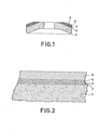
- the base body 1 consists of electrographite.
- the metal layers 2 to 5 are formed by deposition from the gas phase only applied to the bevelled end face of the base body of the rotating anode.
- the rhenium layer 2 is 5 ⁇ m thick.
- the layer 3, which consists of rhenium doped with 5 mol% tantalum, has a thickness of 4 ⁇ m.
- the layer 4 made of pure rhenium is 2 ⁇ m thick and the electron collecting layer 5 made of tungsten has a thickness of 200 ⁇ m.
Landscapes
- Physical Vapour Deposition (AREA)
- X-Ray Techniques (AREA)
- Electrolytic Production Of Metals (AREA)
- Solid Thermionic Cathode (AREA)
- Analysing Materials By The Use Of Radiation (AREA)
Priority Applications (1)
| Application Number | Priority Date | Filing Date | Title |
|---|---|---|---|
| AT80200678T ATE3600T1 (de) | 1979-07-19 | 1980-07-11 | Drehanode fuer roentgenroehren. |
Applications Claiming Priority (2)
| Application Number | Priority Date | Filing Date | Title |
|---|---|---|---|
| DE19792929136 DE2929136A1 (de) | 1979-07-19 | 1979-07-19 | Drehanode fuer roentgenroehren |
| DE2929136 | 1979-07-19 |
Publications (2)
| Publication Number | Publication Date |
|---|---|
| EP0023065A1 true EP0023065A1 (fr) | 1981-01-28 |
| EP0023065B1 EP0023065B1 (fr) | 1983-05-25 |
Family
ID=6076091
Family Applications (1)
| Application Number | Title | Priority Date | Filing Date |
|---|---|---|---|
| EP80200678A Expired EP0023065B1 (fr) | 1979-07-19 | 1980-07-11 | Anode tournante pour tubes à rayons X |
Country Status (5)
| Country | Link |
|---|---|
| US (1) | US4352041A (fr) |
| EP (1) | EP0023065B1 (fr) |
| JP (1) | JPS5618356A (fr) |
| AT (1) | ATE3600T1 (fr) |
| DE (2) | DE2929136A1 (fr) |
Cited By (4)
| Publication number | Priority date | Publication date | Assignee | Title |
|---|---|---|---|---|
| EP0037956A1 (fr) * | 1980-04-11 | 1981-10-21 | Kabushiki Kaisha Toshiba | Anode tournante pour tube radiogène et procédé pour sa fabrication |
| FR2593324A1 (fr) * | 1986-01-17 | 1987-07-24 | Thomson Cgr | Anode tournante avec graphite pour tube radiogene |
| EP0399621A1 (fr) * | 1989-05-26 | 1990-11-28 | Metallwerk Plansee Gesellschaft M.B.H. | Composite de graphite et d'un métal à haut point de fusion |
| US10622182B2 (en) | 2015-05-08 | 2020-04-14 | Plansee Se | X-ray anode |
Families Citing this family (17)
| Publication number | Priority date | Publication date | Assignee | Title |
|---|---|---|---|---|
| USH547H (en) | 1986-11-13 | 1988-11-01 | General Electric Company | X-ray tube target |
| NL8101697A (nl) * | 1981-04-07 | 1982-11-01 | Philips Nv | Werkwijze voor het vervaardigen van een anode en zo verkregen anode. |
| AT376064B (de) * | 1982-02-18 | 1984-10-10 | Plansee Metallwerk | Roentgenroehren-drehanode |
| JPS598252A (ja) * | 1982-07-07 | 1984-01-17 | Hitachi Ltd | X線管用回転ターゲットの製造法 |
| US4573185A (en) * | 1984-06-27 | 1986-02-25 | General Electric Company | X-Ray tube with low off-focal spot radiation |
| US4641334A (en) * | 1985-02-15 | 1987-02-03 | General Electric Company | Composite rotary anode for X-ray tube and process for preparing the composite |
| US4700882A (en) * | 1985-02-15 | 1987-10-20 | General Electric Company | Composite rotary anode for X-ray tube and process for preparing the composite |
| US4978051A (en) * | 1986-12-31 | 1990-12-18 | General Electric Co. | X-ray tube target |
| JPH0731993B2 (ja) * | 1987-03-18 | 1995-04-10 | 株式会社日立製作所 | X線管用ターゲット及びそれを用いたx線管 |
| FR2655191A1 (fr) * | 1989-11-28 | 1991-05-31 | Genral Electric Cgr Sa | Anode pour tube a rayons x. |
| US5204891A (en) * | 1991-10-30 | 1993-04-20 | General Electric Company | Focal track structures for X-ray anodes and method of preparation thereof |
| US5148463A (en) * | 1991-11-04 | 1992-09-15 | General Electric Company | Adherent focal track structures for X-ray target anodes having diffusion barrier film therein and method of preparation thereof |
| US6400800B1 (en) * | 2000-12-29 | 2002-06-04 | Ge Medical Systems Global Technology Company, Llc | Two-step brazed x-ray target assembly |
| DE102005049519B4 (de) * | 2005-01-31 | 2014-10-30 | Medicoat Ag | Drehanodenteller für Röntgenröhren |
| US8165269B2 (en) * | 2008-09-26 | 2012-04-24 | Varian Medical Systems, Inc. | X-ray target with high strength bond |
| DE102009007871B4 (de) * | 2009-02-06 | 2012-04-26 | Fraunhofer-Gesellschaft zur Förderung der angewandten Forschung e.V. | Röntgentarget, Röntgenröhre und Verfahren zur Erzeugung von Röntgenstrahlung |
| FR2962591B1 (fr) | 2010-07-06 | 2017-04-14 | Acerde | Anode pour l'emission de rayons x et procede de fabrication d'une telle anode |
Citations (5)
| Publication number | Priority date | Publication date | Assignee | Title |
|---|---|---|---|---|
| DE1913793A1 (de) * | 1969-03-19 | 1970-10-01 | Ct D Etudes Et De Rech S Des E | Drehanode fuer Roentgenroehre und Bearbeitungsverfahren hierzu |
| US3579022A (en) * | 1967-08-28 | 1971-05-18 | Schwarzkopf Dev Co | Rotary anode for x-ray tube |
| FR2204041A1 (fr) * | 1972-10-20 | 1974-05-17 | Siemens Ag | |
| US3875444A (en) * | 1972-12-06 | 1975-04-01 | Philips Corp | Rotating x-ray anode having a target area made of a tungsten rhenium tantalum alloy |
| US3890521A (en) * | 1971-12-31 | 1975-06-17 | Thomson Csf | X-ray tube target and X-ray tubes utilising such a target |
Family Cites Families (3)
| Publication number | Priority date | Publication date | Assignee | Title |
|---|---|---|---|---|
| NL215843A (fr) * | 1956-03-30 | |||
| AT346981B (de) * | 1976-03-18 | 1978-12-11 | Plansee Metallwerk | Roentgendrehanode und verfahren zu deren herstellung |
| US4145632A (en) * | 1977-04-18 | 1979-03-20 | General Electric Company | Composite substrate for rotating x-ray anode tube |
-
1979
- 1979-07-19 DE DE19792929136 patent/DE2929136A1/de not_active Withdrawn
-
1980
- 1980-07-03 US US06/165,894 patent/US4352041A/en not_active Expired - Lifetime
- 1980-07-11 EP EP80200678A patent/EP0023065B1/fr not_active Expired
- 1980-07-11 DE DE8080200678T patent/DE3063487D1/de not_active Expired
- 1980-07-11 AT AT80200678T patent/ATE3600T1/de not_active IP Right Cessation
- 1980-07-16 JP JP9744180A patent/JPS5618356A/ja active Granted
Patent Citations (5)
| Publication number | Priority date | Publication date | Assignee | Title |
|---|---|---|---|---|
| US3579022A (en) * | 1967-08-28 | 1971-05-18 | Schwarzkopf Dev Co | Rotary anode for x-ray tube |
| DE1913793A1 (de) * | 1969-03-19 | 1970-10-01 | Ct D Etudes Et De Rech S Des E | Drehanode fuer Roentgenroehre und Bearbeitungsverfahren hierzu |
| US3890521A (en) * | 1971-12-31 | 1975-06-17 | Thomson Csf | X-ray tube target and X-ray tubes utilising such a target |
| FR2204041A1 (fr) * | 1972-10-20 | 1974-05-17 | Siemens Ag | |
| US3875444A (en) * | 1972-12-06 | 1975-04-01 | Philips Corp | Rotating x-ray anode having a target area made of a tungsten rhenium tantalum alloy |
Cited By (7)
| Publication number | Priority date | Publication date | Assignee | Title |
|---|---|---|---|---|
| EP0037956A1 (fr) * | 1980-04-11 | 1981-10-21 | Kabushiki Kaisha Toshiba | Anode tournante pour tube radiogène et procédé pour sa fabrication |
| FR2593324A1 (fr) * | 1986-01-17 | 1987-07-24 | Thomson Cgr | Anode tournante avec graphite pour tube radiogene |
| EP0234967A1 (fr) * | 1986-01-17 | 1987-09-02 | General Electric Cgr S.A. | Anode tournante avec graphite pour tube radiogène |
| US4799250A (en) * | 1986-01-17 | 1989-01-17 | Thomson-Cgr | Rotating anode with graphite for X-ray tube |
| EP0399621A1 (fr) * | 1989-05-26 | 1990-11-28 | Metallwerk Plansee Gesellschaft M.B.H. | Composite de graphite et d'un métal à haut point de fusion |
| US5122422A (en) * | 1989-05-26 | 1992-06-16 | Schwarzkopf Technologies Corporation | Composite body made of graphite and high-melting metal |
| US10622182B2 (en) | 2015-05-08 | 2020-04-14 | Plansee Se | X-ray anode |
Also Published As
| Publication number | Publication date |
|---|---|
| EP0023065B1 (fr) | 1983-05-25 |
| JPS6232573B2 (fr) | 1987-07-15 |
| DE3063487D1 (en) | 1983-07-07 |
| DE2929136A1 (de) | 1981-02-05 |
| JPS5618356A (en) | 1981-02-21 |
| US4352041A (en) | 1982-09-28 |
| ATE3600T1 (de) | 1983-06-15 |
Similar Documents
| Publication | Publication Date | Title |
|---|---|---|
| EP0023065B1 (fr) | Anode tournante pour tubes à rayons X | |
| DE3303529C2 (fr) | ||
| DE1951383C3 (de) | Röntgenröhren-Drehanode mit einem Verbundkörper aus einem Schwermetallteil und wenigstens einem Graphitteil und Verfahren zu ihrer Herstellung | |
| EP0399621B1 (fr) | Composite de graphite et d'un métal à haut point de fusion | |
| DE1764681A1 (de) | Drehanode fuer Roentgenroehren | |
| DE1930095A1 (de) | Verfahren zur Herstellung von Drehanoden fuer Roentgenroehren | |
| DE102019108660A1 (de) | Schichtsystem, Bipolarplatte mit einem solchen Schichtsystem und damit gebildete Brennstoffzelle | |
| AT14991U1 (de) | Röntgenanode | |
| DE2945995A1 (de) | Oxidbeschichtete kathode fuer elektronenroehre | |
| DE3028115A1 (de) | Schalterkontaktstueck und verfahren zu seiner herstellung | |
| DE19523163A1 (de) | Gleitlagerteil für ein Flüssigmetallgleitlager | |
| DE2357292B2 (de) | Röntgenröhren-Drehanode mit einer Auftreffläche aus einer Wolfram-Rhenium-Tantal-Legierung | |
| DE69026032T2 (de) | Scandatkathode | |
| EP0488450B1 (fr) | Anode pour tube à rayons X à couche d'oxyde | |
| DE69017877T2 (de) | Röntgendrehanode. | |
| DE68916542T2 (de) | Elektrode für entladungslichtquelle. | |
| EP0235619B1 (fr) | Cathode à incandescence pour tube à rayons X | |
| DE1483302C3 (de) | Verwendung einer Wolfram-Iridiumlegierung für die Anode von Röntgenröhren | |
| DE3444333A1 (de) | Oxidkathode | |
| DE10320700A1 (de) | Vakuumgehäuse für eine Röntgenröhre | |
| EP0168736B1 (fr) | Anode tournante à revêtement de surface pour tubes à rayons X | |
| DE2426387A1 (de) | Bauelement fuer vakuumpumpen | |
| DE2400717C3 (de) | Röntgenröhrendrehanode und Verfahren zu deren Herstellung | |
| DE2202827C3 (de) | Gitterelektrode für elektrische Entladungsgefäße und Verfahren zu ihrer Herstellung | |
| DE2430226A1 (de) | Drehanode fuer roentgenroehren |
Legal Events
| Date | Code | Title | Description |
|---|---|---|---|
| PUAI | Public reference made under article 153(3) epc to a published international application that has entered the european phase |
Free format text: ORIGINAL CODE: 0009012 |
|
| AK | Designated contracting states |
Designated state(s): AT CH DE FR GB NL |
|
| 17P | Request for examination filed |
Effective date: 19810709 |
|
| RAP1 | Party data changed (applicant data changed or rights of an application transferred) |
Owner name: N.V. PHILIPS' GLOEILAMPENFABRIEKEN Owner name: PHILIPS PATENTVERWALTUNG GMBH |
|
| GRAA | (expected) grant |
Free format text: ORIGINAL CODE: 0009210 |
|
| AK | Designated contracting states |
Designated state(s): AT CH DE FR GB LI NL |
|
| REF | Corresponds to: |
Ref document number: 3600 Country of ref document: AT Date of ref document: 19830615 Kind code of ref document: T |
|
| REF | Corresponds to: |
Ref document number: 3063487 Country of ref document: DE Date of ref document: 19830707 |
|
| ET | Fr: translation filed | ||
| PLBE | No opposition filed within time limit |
Free format text: ORIGINAL CODE: 0009261 |
|
| STAA | Information on the status of an ep patent application or granted ep patent |
Free format text: STATUS: NO OPPOSITION FILED WITHIN TIME LIMIT |
|
| 26N | No opposition filed | ||
| PGFP | Annual fee paid to national office [announced via postgrant information from national office to epo] |
Ref country code: NL Payment date: 19840731 Year of fee payment: 5 |
|
| PG25 | Lapsed in a contracting state [announced via postgrant information from national office to epo] |
Ref country code: NL Effective date: 19860201 |
|
| NLV4 | Nl: lapsed or anulled due to non-payment of the annual fee | ||
| PGFP | Annual fee paid to national office [announced via postgrant information from national office to epo] |
Ref country code: DE Payment date: 19910923 Year of fee payment: 12 |
|
| PGFP | Annual fee paid to national office [announced via postgrant information from national office to epo] |
Ref country code: CH Payment date: 19911024 Year of fee payment: 12 |
|
| PGFP | Annual fee paid to national office [announced via postgrant information from national office to epo] |
Ref country code: GB Payment date: 19920630 Year of fee payment: 13 |
|
| PGFP | Annual fee paid to national office [announced via postgrant information from national office to epo] |
Ref country code: AT Payment date: 19920724 Year of fee payment: 13 |
|
| PGFP | Annual fee paid to national office [announced via postgrant information from national office to epo] |
Ref country code: FR Payment date: 19920729 Year of fee payment: 13 |
|
| PG25 | Lapsed in a contracting state [announced via postgrant information from national office to epo] |
Ref country code: LI Effective date: 19920731 Ref country code: CH Effective date: 19920731 |
|
| REG | Reference to a national code |
Ref country code: CH Ref legal event code: PL |
|
| PG25 | Lapsed in a contracting state [announced via postgrant information from national office to epo] |
Ref country code: DE Effective date: 19930401 |
|
| PG25 | Lapsed in a contracting state [announced via postgrant information from national office to epo] |
Ref country code: GB Effective date: 19930711 Ref country code: AT Effective date: 19930711 |
|
| GBPC | Gb: european patent ceased through non-payment of renewal fee |
Effective date: 19930711 |
|
| PG25 | Lapsed in a contracting state [announced via postgrant information from national office to epo] |
Ref country code: FR Effective date: 19940331 |
|
| REG | Reference to a national code |
Ref country code: FR Ref legal event code: ST |