EP0023066B1 - Procédé de fabrication de fibres optiques - Google Patents
Procédé de fabrication de fibres optiques Download PDFInfo
- Publication number
- EP0023066B1 EP0023066B1 EP80200683A EP80200683A EP0023066B1 EP 0023066 B1 EP0023066 B1 EP 0023066B1 EP 80200683 A EP80200683 A EP 80200683A EP 80200683 A EP80200683 A EP 80200683A EP 0023066 B1 EP0023066 B1 EP 0023066B1
- Authority
- EP
- European Patent Office
- Prior art keywords
- tube
- deposition
- quartz glass
- inside diameter
- value
- Prior art date
- Legal status (The legal status is an assumption and is not a legal conclusion. Google has not performed a legal analysis and makes no representation as to the accuracy of the status listed.)
- Expired
Links
Images
Classifications
-
- C—CHEMISTRY; METALLURGY
- C03—GLASS; MINERAL OR SLAG WOOL
- C03B—MANUFACTURE, SHAPING, OR SUPPLEMENTARY PROCESSES
- C03B37/00—Manufacture or treatment of flakes, fibres, or filaments from softened glass, minerals, or slags
- C03B37/01—Manufacture of glass fibres or filaments
- C03B37/012—Manufacture of preforms for drawing fibres or filaments
- C03B37/014—Manufacture of preforms for drawing fibres or filaments made entirely or partially by chemical means, e.g. vapour phase deposition of bulk porous glass either by outside vapour deposition [OVD], or by outside vapour phase oxidation [OVPO] or by vapour axial deposition [VAD]
- C03B37/018—Manufacture of preforms for drawing fibres or filaments made entirely or partially by chemical means, e.g. vapour phase deposition of bulk porous glass either by outside vapour deposition [OVD], or by outside vapour phase oxidation [OVPO] or by vapour axial deposition [VAD] by glass deposition on a glass substrate, e.g. by inside-, modified-, plasma- or plasma modified- chemical vapour deposition [ICVD, MCVD, PCVD, PMCVD], i.e. by thin layer coating on the inside or outside of a glass tube or on a glass rod
- C03B37/01861—Means for changing or stabilising the diameter or form of tubes or rods
-
- C—CHEMISTRY; METALLURGY
- C03—GLASS; MINERAL OR SLAG WOOL
- C03B—MANUFACTURE, SHAPING, OR SUPPLEMENTARY PROCESSES
- C03B37/00—Manufacture or treatment of flakes, fibres, or filaments from softened glass, minerals, or slags
- C03B37/01—Manufacture of glass fibres or filaments
- C03B37/012—Manufacture of preforms for drawing fibres or filaments
- C03B37/014—Manufacture of preforms for drawing fibres or filaments made entirely or partially by chemical means, e.g. vapour phase deposition of bulk porous glass either by outside vapour deposition [OVD], or by outside vapour phase oxidation [OVPO] or by vapour axial deposition [VAD]
- C03B37/018—Manufacture of preforms for drawing fibres or filaments made entirely or partially by chemical means, e.g. vapour phase deposition of bulk porous glass either by outside vapour deposition [OVD], or by outside vapour phase oxidation [OVPO] or by vapour axial deposition [VAD] by glass deposition on a glass substrate, e.g. by inside-, modified-, plasma- or plasma modified- chemical vapour deposition [ICVD, MCVD, PCVD, PMCVD], i.e. by thin layer coating on the inside or outside of a glass tube or on a glass rod
- C03B37/01807—Reactant delivery systems, e.g. reactant deposition burners
- C03B37/01815—Reactant deposition burners or deposition heating means
- C03B37/01823—Plasma deposition burners or heating means
- C03B37/0183—Plasma deposition burners or heating means for plasma within a tube substrate
Definitions
- the invention relates to a process for the production of preforms for the production of optical fibers, wherein quartz glass with any doping by reactive deposition from the gas phase under the action of a non-isothermal plasma is attached to the inside of a quartz glass tube and the internally coated tube collapses to form a solid preform.
- the optical fiber produced therefrom can consist of a core made of doped quartz glass and a jacket made of quartz glass or of a core made of undoped or doped quartz and a first jacket made of doped quartz glass and an outer jacket made of quartz glass.
- DE-C-2 444100 describes a method by which internally coated glass tubes for drawing optical fibers are produced.
- a non-isothermal plasma is used at a pressure of approximately 1.3 to 13 mbar.
- the inside diameter of the tube at the end of the coating should be as small as possible in order to enable a geometrically perfect collapse.
- the object of the invention is therefore to provide a method with which an increased deposition rate is achieved using a non-isothermal plasma without disturbing fine glass particles occurring in the gas phase, the inside diameter of the tube being as small as possible after the coating process, to ensure problem-free collapse.
- the deposition rate M is greater than 0.08 g / min and is set such that during the coating
- the preform thus produced is drawn into a fiber in a manner known per se.
- the starting pipe to be coated and the thickness of the layer to be deposited should be chosen so that the subsequent collapsing step does not pose any additional problems.
- the inner diameter of the tube should be as small as possible at the end of the deposition process before collapsing, because each additional mm increases the risk of errors in the collapse, such as the formation of an elliptical preform, one that is bent over its length Preform or other geometric error.
- the rotational symmetry of the coated tube can best be maintained if the collapse step is as small as possible.
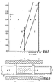
- Limits G1 and G2 are also shown in FIG. 1. Below about 6 mm inner tube diameter, the achievable deposition rates are so low that they become economically uninteresting; with an inner diameter of over 30 mm, the coated tube is very difficult to collapse into a solid, bubble-free, cylindrical preform.
- the equations given are particularly important if, in order to shorten the collapse step, a layer as thick as possible is applied to the inside of the tube. Since the inner diameter of the tube then becomes smaller and smaller, the deposition speed must also be adjusted accordingly. You can then start with a high deposition speed, but you have to reduce it continuously as the inside diameter decreases. You should always stay in area B if possible.
- the temperature of the substrate tube in the experiments was in the range from about 1000 ° C to 12000 ° C. Even at the high deposition rates, an almost complete yield is obtained, ie the entire SiC1 4 fed into the tube together with any dopant in the form of a halide is converted into Si0 2 using the oxygen in the region of the microwave discharge and the dopant in the form of an oxide converted. It is therefore easy to determine the necessary and sufficient halide (SiCl 4 + dopant in the form of the halide) gas flow for any desired deposition rate.
- the oxygen flow results from the fact that the total pressure in the reaction zone is preferably in the range from 1 to 27 mbar and that the stoichiometric flow of oxygen must be at least as great as the halide flow. A triple or larger surplus has turned out to be favorable.
- GeC) 4 , BCI 3 , SiF 4 , PCI 3 and other known dopants can be used as dopants in the form of the halide.
- the plasma is necessary for the activation of the reaction and, with a larger number of molecules to be activated per unit of time, it also requires a greater power supply. If the microwave power is too low, this becomes apparent through the deposition of opaque layers. In practice, the required power is determined by increasing the supplied microwave power in a preliminary test until the layers are deposited crystal-clear.
- the microwave power supplied is at least so great that the diameter of the tube is completely filled with the plasma.
- a rotationally symmetrical energy density in the tube is required for a rotationally symmetrical deposition profile. If the conditions mentioned here are met, it is found that the deposited layers are of fiber-optic quality, regardless of the deposition rate.
- the electron temperature is equal to the gas temperature. Both are typically in the order of tens of thousands of degrees.
- the electron temperature is considerably higher than the gas temperature.
- the electron temperature typically has values of some 10,000 K, the gas The temperature typically increases - depending on the gas type and pressure - by a maximum of a few 100 K.
- FIG. 2 shows the deposition of Si0 2 glass 1 from a gas mixture SiCl 4 / O 2 and any dopant in the form of a halide 2 on the inner wall of a quartz glass tube 3.
- the gas mixture 2 is passed through the pipe 3 in the direction of the arrow.
- a local non-isothermal plasma 4 is generated by ring electrodes 5 and either inductively or capacitively coupled, or generated in a microwave resonator.
- the arrow drawn below the device indicates a relative movement between the tube 3 and the plasma-exciting device in the axial direction.
- the plasma 4 is overlaid by a furnace 6, a temperature zone that exceeds the plasma range.
- the inside of a quartz glass tube was coated with quartz glass which was doped with Ge0 2 and B 2 0 3 .
- the microwave frequency used was 2.45 GHz, the speed of the reaction zone was 3 m / min and the length of the deposition area was 35 cm.
- the substrate temperature was 1050 ° C, the total pressure was 13 mbar.
- the microwave power was 200 W.
- the quartz tube used had an inner diameter of 6 mm and an outer diameter of 8 mm.
- the SiCl 4 flow was 30 cm 3 / min (based on standard conditions, temperature 0 ° C, pressure 1 bar - this also applies to the following information of this type), the GeCl 4 flow became linear with the time until the end of the experiment increased from 0 cm 3 / min to 4 cm 3 / min.
- the O 2 flow was 150 cm 3 / min and the BCI 3 flow was 3 cm 3 / min.
- the deposition rate was 0.08 g / min. This deposition rate was already at the critical limit. A further increase in the deposition rate led to the formation of fine glass particles in the gas phase.
- Example 1 Compared to Example 1, the following conditions were changed: the inside diameter of 8 mm, the outside diameter of 10 mm, the SiC1 4 flow, which here was 60 cm 3 / min, the CeCl 4 flow, which went from 0 to 7.5 cm 3 / min was increased, the BCI 3 flow with 5 cm 3 / min and the total pressure with 20 mbar.
- the deposition rate was 0.15 g / min.
- a microwave power of 500 W was used.
- the quartz glass tube used had an inner diameter of 11.5 mm and an outer diameter of 14 mm.
- the SiCl 4 flow was initially 132 cm 3 / min and was linearly reduced to 116 cm 3 / min at the time t o .
- the BCI 3 flow was initially 21 cm 3 / min and was gradually reduced to 7.5 cm 3 / min.
- the GeCI 4 current was increased linearly with the time from 0 cm 3 / min to the final value of 16 cm 3 / min.
- the oxygen flow was 500 cm 3 / min and rose linearly from time to 595 cm3 / min.
- the average deposition rate was 0.3 g / min.
- the substrate temperature was 1050 ° C, the pressure in the reaction zone was 13 mbar.
- the method described can be used both for the deposition of doped and undoped quartz glass, specifically for the production of monomode and multimode fibers.
- the doping can be kept constant during the deposition (step index fiber), or can also increase or decrease (gradient fiber).
Landscapes
- Chemical & Material Sciences (AREA)
- Engineering & Computer Science (AREA)
- Geochemistry & Mineralogy (AREA)
- Life Sciences & Earth Sciences (AREA)
- General Chemical & Material Sciences (AREA)
- General Life Sciences & Earth Sciences (AREA)
- Chemical Kinetics & Catalysis (AREA)
- Manufacturing & Machinery (AREA)
- Materials Engineering (AREA)
- Organic Chemistry (AREA)
- Physics & Mathematics (AREA)
- Plasma & Fusion (AREA)
- Manufacture, Treatment Of Glass Fibers (AREA)
- Glass Compositions (AREA)
- Multicomponent Fibers (AREA)
Claims (3)


Priority Applications (1)
| Application Number | Priority Date | Filing Date | Title |
|---|---|---|---|
| AT80200683T ATE19388T1 (de) | 1979-07-19 | 1980-07-14 | Verfahren zur herstellung von lichtleitfasern. |
Applications Claiming Priority (2)
| Application Number | Priority Date | Filing Date | Title |
|---|---|---|---|
| DE19792929166 DE2929166A1 (de) | 1979-07-19 | 1979-07-19 | Verfahren zur herstellung von lichtleitfasern |
| DE2929166 | 1979-07-19 |
Publications (2)
| Publication Number | Publication Date |
|---|---|
| EP0023066A1 EP0023066A1 (fr) | 1981-01-28 |
| EP0023066B1 true EP0023066B1 (fr) | 1986-04-23 |
Family
ID=6076114
Family Applications (1)
| Application Number | Title | Priority Date | Filing Date |
|---|---|---|---|
| EP80200683A Expired EP0023066B1 (fr) | 1979-07-19 | 1980-07-14 | Procédé de fabrication de fibres optiques |
Country Status (9)
| Country | Link |
|---|---|
| US (1) | US4314833A (fr) |
| EP (1) | EP0023066B1 (fr) |
| JP (1) | JPS5945609B2 (fr) |
| AT (1) | ATE19388T1 (fr) |
| AU (1) | AU530122B2 (fr) |
| BR (1) | BR8004434A (fr) |
| CA (1) | CA1157654A (fr) |
| DE (2) | DE2929166A1 (fr) |
| ZA (1) | ZA803946B (fr) |
Families Citing this family (40)
| Publication number | Priority date | Publication date | Assignee | Title |
|---|---|---|---|---|
| CA1173813A (fr) * | 1982-02-04 | 1984-09-04 | Lawrence J. O'connor | Bobinage de ruban par detrancanage sur roquet |
| DE3206144A1 (de) * | 1982-02-20 | 1983-09-01 | Licentia Patent-Verwaltungs-Gmbh, 6000 Frankfurt | Verfahren zur herstellung eines lichtwellenleiters |
| NL8201453A (nl) * | 1982-04-06 | 1983-11-01 | Philips Nv | Werkwijze voor de vervaardiging van optische vezels. |
| DE3222189A1 (de) * | 1982-06-12 | 1984-01-26 | Hans Dr.Rer.Nat. 5370 Kall Beerwald | Plasmaverfahren zur innenbeschichtung von rohren mit dielektrischem material |
| NL8302127A (nl) * | 1983-06-15 | 1985-01-02 | Philips Nv | Werkwijze en inrichting voor de vervaardiging van optische vezels. |
| CA1242889A (fr) * | 1983-07-16 | 1988-10-11 | Peter E.E. Geittner | Fabrication de fibres optiques |
| JPS6198240U (fr) * | 1984-12-05 | 1986-06-24 | ||
| DE3445239A1 (de) * | 1984-12-12 | 1986-06-19 | Philips Patentverwaltung Gmbh, 2000 Hamburg | Verfahren zur herstellung von lichtleitfasern |
| US5188648A (en) * | 1985-07-20 | 1993-02-23 | U.S. Philips Corp. | Method of manufacturing optical fibres |
| DE3635034A1 (de) * | 1986-10-15 | 1988-04-21 | Philips Patentverwaltung | Verfahren zur herstellung von lichtleitfasern |
| DE3720030A1 (de) * | 1987-06-16 | 1988-12-29 | Philips Patentverwaltung | Verfahren zur herstellung von lichtleitfasern |
| US5203897A (en) * | 1989-11-13 | 1993-04-20 | Corning Incorporated | Method for making a preform doped with a metal oxide |
| US5522003A (en) * | 1993-03-02 | 1996-05-28 | Ward; Robert M. | Glass preform with deep radial gradient layer and method of manufacturing same |
| NL1017523C2 (nl) | 2001-03-07 | 2002-09-10 | Draka Fibre Technology Bv | Werkwijze ter vervaardiging van een optische vezel die geschikt is voor hoge transmissiesnelheden. |
| US6687445B2 (en) * | 2001-06-25 | 2004-02-03 | Nufern | Double-clad optical fiber for lasers and amplifiers |
| US20030115909A1 (en) * | 2001-12-21 | 2003-06-26 | House Keith L. | Plasma chemical vapor deposition methods and apparatus |
| NL1020358C2 (nl) * | 2002-04-10 | 2003-10-13 | Draka Fibre Technology Bv | Werkwijze en inrichting ter vervaardiging van optische voorvormen, alsmede de daarmee verkregen optische vezels. |
| AU2003244251A1 (en) * | 2002-06-29 | 2004-01-19 | Lg Cable Ltd. | Method for fabricating optical fiber preform without hydroxyl group in core |
| NL1022087C2 (nl) * | 2002-12-05 | 2004-06-08 | Draka Fibre Technology Bv | Werkwijze ter vervaardiging van een optische vezel. |
| NL1025155C2 (nl) * | 2003-12-30 | 2005-07-04 | Draka Fibre Technology Bv | Inrichting voor het uitvoeren van PCVD, alsmede werkwijze voor het vervaardigen van een voorvorm. |
| FR2893149B1 (fr) * | 2005-11-10 | 2008-01-11 | Draka Comteq France | Fibre optique monomode. |
| FR2899693B1 (fr) * | 2006-04-10 | 2008-08-22 | Draka Comteq France | Fibre optique monomode. |
| FR2903501B1 (fr) * | 2006-07-04 | 2008-08-22 | Draka Comteq France Sa | Fibre optique dopee au fluor |
| NL1032867C2 (nl) * | 2006-11-14 | 2008-05-15 | Draka Comteq Bv | Inrichting en een werkwijze voor het uitvoeren van een depositieproces van het type PCVD. |
| DK2206001T3 (da) * | 2007-11-09 | 2014-07-07 | Draka Comteq Bv | Optisk fiber, der er modstandsdygtig over for mikrobøjning |
| US8252387B2 (en) * | 2007-12-10 | 2012-08-28 | Ofs Fitel, Llc | Method of fabricating optical fiber using an isothermal, low pressure plasma deposition technique |
| US8857372B2 (en) * | 2007-12-10 | 2014-10-14 | Ofs Fitel, Llc | Method of fabricating optical fiber using an isothermal, low pressure plasma deposition technique |
| FR2930997B1 (fr) * | 2008-05-06 | 2010-08-13 | Draka Comteq France Sa | Fibre optique monomode |
| EP2518546B1 (fr) | 2011-04-27 | 2018-06-20 | Draka Comteq B.V. | Fibre optique multimodale résistante aux rayonnements à bande passante élevée |
| NL2006688C2 (nl) * | 2011-04-29 | 2012-10-30 | Draka Comteq Bv | Werkwijze voor het vervaardigen van een primaire voorvorm voor optische vezels. |
| DK2527893T3 (da) | 2011-05-27 | 2013-12-16 | Draka Comteq Bv | Optisk singlemode fiber |
| ES2451369T3 (es) | 2011-06-09 | 2014-03-26 | Draka Comteq Bv | Fibra óptica de modo único |
| DK2541292T3 (en) | 2011-07-01 | 2014-12-01 | Draka Comteq Bv | A multimode optical fiber |
| NL2007831C2 (en) | 2011-11-21 | 2013-05-23 | Draka Comteq Bv | Apparatus and method for carrying out a pcvd deposition process. |
| NL2010724C2 (en) | 2013-04-26 | 2014-10-29 | Draka Comteq Bv | A pcvd method for manufacturing a primary preform for optical fibers. |
| NL2011077C2 (en) | 2013-07-01 | 2015-01-05 | Draka Comteq Bv | A method for manufacturing a precursor for a primary preform for optical fibres by means of an internal plasma chemical vapour deposition (pcvd) process. |
| NL2011075C2 (en) * | 2013-07-01 | 2015-01-05 | Draka Comteq Bv | Pcvd process with removal of substrate tube. |
| PT3084490T (pt) * | 2013-12-20 | 2021-02-05 | Draka Comteq Bv | Fibra monomodo com um núcleo trapezoidal que exibe perdas reduzidas |
| NL2012857B1 (en) | 2014-05-22 | 2016-03-07 | Draka Comteq Bv | Apparatus and method for carrying out a plasma deposition process. |
| PL3729151T3 (pl) | 2017-12-21 | 2022-07-25 | Draka Comteq France | Niewrażliwy na zginanie światłowód jednomodowy z płytkim rowkiem oraz odpowiedni system optyczny |
Citations (1)
| Publication number | Priority date | Publication date | Assignee | Title |
|---|---|---|---|---|
| DE2444100C3 (de) * | 1974-09-14 | 1979-04-12 | Philips Patentverwaltung Gmbh, 2000 Hamburg | Verfahren zur Herstellung von innenbeschichteten Glasrohren zum Ziehen von Lichtleitfasern |
Family Cites Families (7)
| Publication number | Priority date | Publication date | Assignee | Title |
|---|---|---|---|---|
| GB1427327A (en) * | 1972-06-08 | 1976-03-10 | Standard Telephones Cables Ltd | Glass optical fibres |
| JPS4983453A (fr) * | 1972-12-14 | 1974-08-10 | ||
| CA1050833A (fr) * | 1974-02-22 | 1979-03-20 | John B. Macchesney | Fabrication de fibre optique par reaction homogene en zone chaude mobile |
| US4145456A (en) * | 1974-09-14 | 1979-03-20 | Dieter Kuppers | Method of producing internally coated glass tubes for the drawing of fibre optic light conductors |
| GB1550820A (en) * | 1975-07-04 | 1979-08-22 | Standard Telephones Cables Ltd | Optical fibre manufacture |
| DE2538313C3 (de) * | 1975-08-28 | 1981-11-05 | Heraeus Quarzschmelze Gmbh, 6450 Hanau | Verfahren zur Herstellung eines Vorproduktes für die Erzeugung eines optischen, selbstfokussierenden Lichtleiters |
| GB1578826A (en) * | 1976-03-25 | 1980-11-12 | Western Electric Co | Methods for fabricating optical fibre preforms |
-
1979
- 1979-07-19 DE DE19792929166 patent/DE2929166A1/de not_active Withdrawn
-
1980
- 1980-07-01 ZA ZA00803946A patent/ZA803946B/xx unknown
- 1980-07-10 CA CA000355931A patent/CA1157654A/fr not_active Expired
- 1980-07-14 EP EP80200683A patent/EP0023066B1/fr not_active Expired
- 1980-07-14 AT AT80200683T patent/ATE19388T1/de active
- 1980-07-14 DE DE8080200683T patent/DE3071565D1/de not_active Expired
- 1980-07-16 US US06/169,348 patent/US4314833A/en not_active Expired - Lifetime
- 1980-07-16 BR BR8004434A patent/BR8004434A/pt unknown
- 1980-07-16 JP JP55097442A patent/JPS5945609B2/ja not_active Expired
- 1980-07-16 AU AU60437/80A patent/AU530122B2/en not_active Ceased
Patent Citations (1)
| Publication number | Priority date | Publication date | Assignee | Title |
|---|---|---|---|---|
| DE2444100C3 (de) * | 1974-09-14 | 1979-04-12 | Philips Patentverwaltung Gmbh, 2000 Hamburg | Verfahren zur Herstellung von innenbeschichteten Glasrohren zum Ziehen von Lichtleitfasern |
Also Published As
| Publication number | Publication date |
|---|---|
| AU530122B2 (en) | 1983-06-30 |
| AU6043780A (en) | 1981-01-22 |
| US4314833A (en) | 1982-02-09 |
| ATE19388T1 (de) | 1986-05-15 |
| JPS5945609B2 (ja) | 1984-11-07 |
| DE2929166A1 (de) | 1981-01-29 |
| BR8004434A (pt) | 1981-01-27 |
| DE3071565D1 (en) | 1986-05-28 |
| ZA803946B (en) | 1982-02-24 |
| CA1157654A (fr) | 1983-11-29 |
| EP0023066A1 (fr) | 1981-01-28 |
| JPS5617942A (en) | 1981-02-20 |
Similar Documents
| Publication | Publication Date | Title |
|---|---|---|
| EP0023066B1 (fr) | Procédé de fabrication de fibres optiques | |
| EP1000909B1 (fr) | Procédé de fabrication d'une préforme pour une fibre optique et un tube de substrat adapté pour l'utilisation dans le procédé | |
| DE2434717C2 (de) | Verfahren zur Herstellung eines Glasfaser-Lichtleiters | |
| DE69017397T2 (de) | Verfahren zur Herstellung einer optischen Faser und nach diesem Verfahren hergestellte Faser. | |
| DE2835326C2 (de) | Verfahren zur Herstellung eines Glas-Rohlings zum Ausziehen zu einer optischen Faser und Herstellung einer optischen Übertragungsfaser | |
| DE69319999T2 (de) | Verfahren zur Herstellung eines grossen Quarzglasrohres, sowie einer Vorform und einer optischen Faser | |
| DE2930398C2 (fr) | ||
| DE2906070C2 (de) | Verfahren zum Herstellen von optischen Wellenleitern | |
| DE3887060T2 (de) | Verfahren zur Herstellung von Glasvorformen für optische Fasern. | |
| EP0309027A1 (fr) | Procédé de fabrication d'un fibre optique monomode | |
| DE2711295A1 (de) | Verfahren zum herstellen einer optischen faser mit verbesserter kreisfoermigkeit im querschnitt | |
| EP2714603B1 (fr) | Procédé de fabrication d'un demi-produit destiné à la fabrication d'une fibre optique optimisée en flexion | |
| DE2642949A1 (de) | Verfahren zur herstellung von innenbeschichteten glasrohren zum ziehen von lichtleitfasern | |
| EP0392599A2 (fr) | Procédé pour la fabrication de corps en verre avec des domaines de réfraction optique différente | |
| DE2827303C2 (de) | Verfahren zur Herstellung eines Glasgegenstandes und dessen Anwendung | |
| DE69512557T2 (de) | Herstellungsverfahren für optischen Wellenleiter | |
| EP0198118A1 (fr) | Fibre optique monomode en verre de silice et sa méthode de fabrication | |
| EP0295745B1 (fr) | Procédé de fabrication de fibres optiques | |
| DE3635819C2 (fr) | ||
| DE3820217A1 (de) | Lichtwellenleiter, insbesondere einmodenfaser | |
| DE4209004C2 (de) | Verfahren und Vorrichtung zur Herstellung einer Lichtwellenleiter-Vorform | |
| DE102005034594B4 (de) | Verfahren zur Herstellung von Glasfaserpreformen mit einem großen Kerndurchmesser | |
| DE10035951C2 (de) | Verfahren zur Herstellung eines Bauteils für die Herstellung optischer Fasern, sowie Verwendung des Bauteils | |
| EP0536631B1 (fr) | Procédé de fabrication d'une préforme pour fibres optiques | |
| EP0163071B1 (fr) | Procédé pour la fabrication d'une préforme pour l'étirage de fibres optiques |
Legal Events
| Date | Code | Title | Description |
|---|---|---|---|
| PUAI | Public reference made under article 153(3) epc to a published international application that has entered the european phase |
Free format text: ORIGINAL CODE: 0009012 |
|
| AK | Designated contracting states |
Designated state(s): AT BE DE FR GB IT NL SE |
|
| 17P | Request for examination filed |
Effective date: 19810709 |
|
| RAP1 | Party data changed (applicant data changed or rights of an application transferred) |
Owner name: N.V. PHILIPS' GLOEILAMPENFABRIEKEN Owner name: PHILIPS PATENTVERWALTUNG GMBH |
|
| ITF | It: translation for a ep patent filed | ||
| GRAA | (expected) grant |
Free format text: ORIGINAL CODE: 0009210 |
|
| AK | Designated contracting states |
Kind code of ref document: B1 Designated state(s): AT BE DE FR GB IT NL SE |
|
| REF | Corresponds to: |
Ref document number: 19388 Country of ref document: AT Date of ref document: 19860515 Kind code of ref document: T |
|
| REF | Corresponds to: |
Ref document number: 3071565 Country of ref document: DE Date of ref document: 19860528 |
|
| ITF | It: translation for a ep patent filed | ||
| PGFP | Annual fee paid to national office [announced via postgrant information from national office to epo] |
Ref country code: AT Payment date: 19860715 Year of fee payment: 7 |
|
| ET | Fr: translation filed | ||
| PLBE | No opposition filed within time limit |
Free format text: ORIGINAL CODE: 0009261 |
|
| STAA | Information on the status of an ep patent application or granted ep patent |
Free format text: STATUS: NO OPPOSITION FILED WITHIN TIME LIMIT |
|
| 26N | No opposition filed | ||
| PG25 | Lapsed in a contracting state [announced via postgrant information from national office to epo] |
Ref country code: AT Effective date: 19880714 |
|
| PGFP | Annual fee paid to national office [announced via postgrant information from national office to epo] |
Ref country code: BE Payment date: 19900705 Year of fee payment: 11 |
|
| PGFP | Annual fee paid to national office [announced via postgrant information from national office to epo] |
Ref country code: SE Payment date: 19900726 Year of fee payment: 11 |
|
| ITTA | It: last paid annual fee | ||
| PGFP | Annual fee paid to national office [announced via postgrant information from national office to epo] |
Ref country code: NL Payment date: 19900731 Year of fee payment: 11 |
|
| PG25 | Lapsed in a contracting state [announced via postgrant information from national office to epo] |
Ref country code: SE Effective date: 19910715 |
|
| PG25 | Lapsed in a contracting state [announced via postgrant information from national office to epo] |
Ref country code: BE Effective date: 19910731 |
|
| BERE | Be: lapsed |
Owner name: N.V. PHILIPS' GLOEILAMPENFABRIEKEN Effective date: 19910731 |
|
| PG25 | Lapsed in a contracting state [announced via postgrant information from national office to epo] |
Ref country code: NL Effective date: 19920201 |
|
| NLV4 | Nl: lapsed or anulled due to non-payment of the annual fee | ||
| EUG | Se: european patent has lapsed |
Ref document number: 80200683.3 Effective date: 19920210 |
|
| REG | Reference to a national code |
Ref country code: FR Ref legal event code: CD |
|
| REG | Reference to a national code |
Ref country code: GB Ref legal event code: 732E |
|
| REG | Reference to a national code |
Ref country code: FR Ref legal event code: TP |
|
| PGFP | Annual fee paid to national office [announced via postgrant information from national office to epo] |
Ref country code: FR Payment date: 19990430 Year of fee payment: 20 |
|
| PGFP | Annual fee paid to national office [announced via postgrant information from national office to epo] |
Ref country code: GB Payment date: 19990714 Year of fee payment: 20 |
|
| PGFP | Annual fee paid to national office [announced via postgrant information from national office to epo] |
Ref country code: DE Payment date: 19990929 Year of fee payment: 20 |
|
| PG25 | Lapsed in a contracting state [announced via postgrant information from national office to epo] |
Ref country code: GB Free format text: LAPSE BECAUSE OF EXPIRATION OF PROTECTION Effective date: 20000713 |
|
| REG | Reference to a national code |
Ref country code: GB Ref legal event code: PE20 Effective date: 20000713 |