EP0023132A1 - Überbaukonstruktion - Google Patents
Überbaukonstruktion Download PDFInfo
- Publication number
- EP0023132A1 EP0023132A1 EP80302409A EP80302409A EP0023132A1 EP 0023132 A1 EP0023132 A1 EP 0023132A1 EP 80302409 A EP80302409 A EP 80302409A EP 80302409 A EP80302409 A EP 80302409A EP 0023132 A1 EP0023132 A1 EP 0023132A1
- Authority
- EP
- European Patent Office
- Prior art keywords
- upright
- deck
- pivoting
- adjacent
- construction method
- Prior art date
- Legal status (The legal status is an assumption and is not a legal conclusion. Google has not performed a legal analysis and makes no representation as to the accuracy of the status listed.)
- Withdrawn
Links
- 238000010276 construction Methods 0.000 title claims abstract description 19
- 238000000034 method Methods 0.000 claims abstract description 19
- 238000009751 slip forming Methods 0.000 claims abstract description 19
- 230000015572 biosynthetic process Effects 0.000 claims description 5
- 238000011065 in-situ storage Methods 0.000 abstract description 7
- 230000000694 effects Effects 0.000 description 2
- 238000005452 bending Methods 0.000 description 1
- 238000005266 casting Methods 0.000 description 1
- 239000000463 material Substances 0.000 description 1
- 210000002435 tendon Anatomy 0.000 description 1
Images



Classifications
-
- E—FIXED CONSTRUCTIONS
- E01—CONSTRUCTION OF ROADS, RAILWAYS, OR BRIDGES
- E01D—CONSTRUCTION OF BRIDGES, ELEVATED ROADWAYS OR VIADUCTS; ASSEMBLY OF BRIDGES
- E01D21/00—Methods or apparatus specially adapted for erecting or assembling bridges
- E01D21/08—Methods or apparatus specially adapted for erecting or assembling bridges by rotational movement of the bridge or bridge sections
-
- E—FIXED CONSTRUCTIONS
- E01—CONSTRUCTION OF ROADS, RAILWAYS, OR BRIDGES
- E01D—CONSTRUCTION OF BRIDGES, ELEVATED ROADWAYS OR VIADUCTS; ASSEMBLY OF BRIDGES
- E01D2101/00—Material constitution of bridges
- E01D2101/20—Concrete, stone or stone-like material
- E01D2101/24—Concrete
- E01D2101/26—Concrete reinforced
Definitions
- This invention relates to the construction of decks of structures where the deck is to be supported by spaced - apart upright pillars or piers.
- the invention is concerned with the construction of bridge decks.
- the techniques of slipforming and jumpforming are extended to the construction of concrete decks, which when finally in-situ are supported on spaced-apart uprights, in such a way that movement of each member of a deck from an upright position in which it is slipformed or jumpformed into a final position is accomplished in a simple manner and with a minimum of additional equipment.
- a method of constructing a deck in concrete comprising forming in upright position by the slipforming technique or by the jumpforming technique a plurality of members; characterised in that each member so formed is to be a member of said deck, and is so formed adjacent an upright that is to support it in its final position; and in that after its formation each so formed member is pivoted about the upright that is to support it for moving it into a final position in which it is to become a part of the deck.
- slipforming or jumpforming are.utilised in the formation of the deck members, and as each member so formed is formed adjacent an upright, the member only has to be pivoted into its final position and the major component required to effect this pivoting, i.e. the upright, is itself a part of the finished construction. Furthermore, pivoting is facilitated by the fact that it takes place above a point in a mid-way zone of the member.
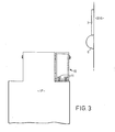
- the Figures relate to the approach spans of a road-carrying river bridge in which in the completed structure pairs of side-by-side uprights in the form of piers 1 carry a bridge deck 2.
- the piers 1 are constructed in-situ, in conventional fashion (for example by slipforming or jumpforming) on previously driven piles.
- a first span 2A and part of a second span 2B of the bridge deck are also constructed in-situ on trestling so that first and second piers 1A and 1B are spanned and in addition the deck extends towards the third pair of piers 1C.
- a part span 2K is constructed in conventional fashion together with the main bridge spans. Construction of the bridge deck at the approach part of the bridge is carried out making use of either the slipforming technique or the jumpforming technique and will now be described with reference to slipforming.
- Adjacent the third pair of piers 1C slip forms are set-up on top of the pile cap on which the piers stand, or at beach level if there is a beach, in which case mass concrete walls or pillars are provided to carry loads down to the pile caps under the beach.
- the slip forms are positioned to form two side-by-side upright concrete box beams 2C/D each disposed about one metre from the adjacent face of one or other of the piers, which beams are to become members of the deck.
- temporary supports 3 are cast to some two or four metres in height.
- each box beam 2C/D is cast on these supports.
- slipforming is carried out continously until the level of the top of the adjacent pier 1C is reached. At this point slipforming is stopped and a diaphram section 4 is cast in the beam. Up to this level the beam is free standing but at this stage temporary wind bracing 5 is installed to transfer wind loads to the top of the adjacent pier. After construction of the diaphragm section, slipforming is re-commenced to complete the box beam.
- the inside shutters of the slipforming equipment are moved in and out to accommodate changes in flange and web thickness and the sliding members are steered as necessary to form any required overall curvature to the beam in the longitudinal plane.
- Pockets are formed for providing a number of prestressing anchorages spread along the beam.
- the beam is prestressed by straight bars or tendons inserted into ducts cast in the beam. This prestressing is carried out from platforms lowered and raised inside the beam after completion of the slipforming.
- pairs of upright box beams 2D/F, 2E/F, 2F/G are constructed adjacent each pair of piers 1D, IE, IF «
- the overall. length of each beam is chosen in relation to the height-of the adjacent pier and the acceptance load that can be applied during 'transfer of the beam to its final position.
- Pairs of beams can be constructed at all the pairs of piers before further work is carried out (as shown in Figure 1), or further work at each pier pair can be commenced once the pair of beams at that pier pair is completed.
- Figure 2 in particular is drawn as if there is only one beam and one pier at each pier location (and such could be the case in some constructions, as, equally, there could be more than two beams and piers at each pier location).
- Sets of cables 8 and 9 are connected to extend from an upper zone (in the case illustrated the top) of this beam (illustrated for one of the beams 2D/E in Figure 2) away from the already-constructed part of the deck down to the base of the pier (pier 1E in Figure 2) that is next adjacent the pier (1D in Figure 2) immediately adjacent the beams; and from a lower zone (in the case illustrated, the base) of the beam up to the free end of the already-constructed deck part.
- Further cabling 9A is installed between the free end of the already-constructed span 2B and the foot of the first free-standing pier 1C, this being left in place whilst the beams are transferred to their final positions and thereafter removed.
- the wind bracing 5 is removed and using the cables 8 and 9 and the jacks the beam is tilted so that the one metre gap between the beam and the immediately adjacent pier is closed at the top of the pier (see beam 2E/F and pier 1E in Figure 2).
- the rocker bearings 6 are installed, if not already fitted and any necessary adjustments made to them, to the bearing plates 7 and to landing stools 10 for the bearings 6 at the top of the pier.
- Levelling screws 11 are provided to facilitate such adjustment.
- the jacks at the bottom of the beam are relieved of load and pivoting of the beam is then effected, utilising the cables 8 and 9, so that the beam pivots about the top of its adjacent pier with the bearings 6 rocking on the landing stools 10.
- the beam is jacked up so that the rocker bearings 6 can be removed and is then lowered so that the bearing plates 7 come to rest on permanent bearings (not shown) installed on the concrete pier.
- the beam is tilted sideways to obtain any camber required and is connected to the already-constructed deck part. It will be noted that this connection is made at approximately mid-span between piers.
- connection is made utilising short lengths of prestressing bar after a tolerance gap has been filled, in-situ, with concrete.
- Each beam at a pair of piers is transferred to its final position in this way before transfer of the beams at the next pair of piers is commenced.
- the beams do not exactly balance when they are pivoted, the degree of out of balance being chosen so that maximum use is made of the pier heights.
- the out-of-balance load is finally taken at the cantilevered end of the already-constructed deck part so that final stress is not increased.
- Temporary dead load bending moments do not exceed the dead load plus live load moments for which the deck as a whole is designed.
- the pier 1D is approximately 32.7 metres high and the overall length of the beam 2D/E is approximately 55.3 metres.
- the pivot point for the beam is at approximately 25.9 metres from what will be its cantilevered end so that the length of the beam on the other side of the pivot point is approximately 29.4 metres.
- the beam weighs approximately 1320 tons.
- the load in the cables 8 at the commencement of pivoting is 250 tons and is 0 tons at the end of pivoting (these cables being connected to what is then the cantilevered end of the beam).
- the load in the cables 9 is 0 tons at the commencement of pivoting, the load at this end of the beam immediately prior to making good its connection with the already-constructed deck part being about 70 tons.
Landscapes
- Engineering & Computer Science (AREA)
- Architecture (AREA)
- Civil Engineering (AREA)
- Structural Engineering (AREA)
- Bridges Or Land Bridges (AREA)
Applications Claiming Priority (2)
| Application Number | Priority Date | Filing Date | Title |
|---|---|---|---|
| GB7925219 | 1979-07-19 | ||
| GB7925219A GB2054013A (en) | 1979-07-19 | 1979-07-19 | Method of constructing a deck |
Publications (1)
| Publication Number | Publication Date |
|---|---|
| EP0023132A1 true EP0023132A1 (de) | 1981-01-28 |
Family
ID=10506619
Family Applications (1)
| Application Number | Title | Priority Date | Filing Date |
|---|---|---|---|
| EP80302409A Withdrawn EP0023132A1 (de) | 1979-07-19 | 1980-07-17 | Überbaukonstruktion |
Country Status (4)
| Country | Link |
|---|---|
| EP (1) | EP0023132A1 (de) |
| AU (1) | AU6062480A (de) |
| CA (1) | CA1137711A (de) |
| GB (1) | GB2054013A (de) |
Cited By (7)
| Publication number | Priority date | Publication date | Assignee | Title |
|---|---|---|---|---|
| DE102006039551B3 (de) * | 2006-08-23 | 2007-09-20 | Kollegger, Johann, Prof. Dr.-Ing. | Brückenklappverfahren |
| CN106836008A (zh) * | 2017-02-15 | 2017-06-13 | 许昌义 | 一种桥梁平衡式竖转的施工方法 |
| CN107313359A (zh) * | 2016-04-27 | 2017-11-03 | 成都亚佳工程新技术开发有限公司 | 一种通用免称重钢桥转体球铰系统 |
| CN108316161A (zh) * | 2018-01-18 | 2018-07-24 | 重庆大学 | 桥梁自动转体北斗定位系统 |
| RU2666164C2 (ru) * | 2016-05-26 | 2018-09-06 | Александр Николаевич Головин | Сборка пролётов мостов при помощи шарнира |
| CN109487704A (zh) * | 2018-10-29 | 2019-03-19 | 中国建筑第六工程局有限公司 | 一种水平转体桥二次转体施工方法 |
| CN113512932A (zh) * | 2021-03-19 | 2021-10-19 | 宁波市政工程建设集团股份有限公司 | 预应力钢束连接的预制小箱梁式隐盖梁及其施工方法 |
Families Citing this family (2)
| Publication number | Priority date | Publication date | Assignee | Title |
|---|---|---|---|---|
| CN111236043A (zh) * | 2020-01-10 | 2020-06-05 | 山西大学 | 一种自适应调高新型路桥搭板连接结构 |
| CN112064518B (zh) * | 2020-08-21 | 2022-06-10 | 中建协和建设有限公司 | 一种桥梁桥墩组合转体支座 |
Citations (5)
| Publication number | Priority date | Publication date | Assignee | Title |
|---|---|---|---|---|
| AT202587B (de) * | 1957-08-02 | 1959-03-10 | Alpenland Baugesellschaft M B | Verfahren zur Herstellung von Brücken, insbesondere Schluchtbrücken |
| FR1234757A (fr) * | 1959-05-19 | 1960-10-19 | Procédé de construction de ponts en béton, et ponts ainsi construits | |
| DE1684464B1 (de) * | 1967-04-06 | 1971-01-21 | Schultz Fademrecht Dipl Ing Ge | Verfahren zur Herstellung von Stahlbeton- und Spannbetontragwerken |
| DE2017714A1 (de) * | 1970-04-14 | 1971-10-28 | Schultz-Fademrecht, Dipl.-Ing. Gerhard, 4400 Münster | Verfahren zur Herstellung von Stahlbeton- und Spannbetontragwerken |
| DE2422984A1 (de) * | 1973-07-10 | 1975-01-30 | Rella & Co Bauges | Verfahren zur herstellung von langgestreckten massivtragwerken |
-
1979
- 1979-07-19 GB GB7925219A patent/GB2054013A/en not_active Withdrawn
-
1980
- 1980-07-17 EP EP80302409A patent/EP0023132A1/de not_active Withdrawn
- 1980-07-18 AU AU60624/80A patent/AU6062480A/en not_active Abandoned
- 1980-07-18 CA CA000356568A patent/CA1137711A/en not_active Expired
Patent Citations (5)
| Publication number | Priority date | Publication date | Assignee | Title |
|---|---|---|---|---|
| AT202587B (de) * | 1957-08-02 | 1959-03-10 | Alpenland Baugesellschaft M B | Verfahren zur Herstellung von Brücken, insbesondere Schluchtbrücken |
| FR1234757A (fr) * | 1959-05-19 | 1960-10-19 | Procédé de construction de ponts en béton, et ponts ainsi construits | |
| DE1684464B1 (de) * | 1967-04-06 | 1971-01-21 | Schultz Fademrecht Dipl Ing Ge | Verfahren zur Herstellung von Stahlbeton- und Spannbetontragwerken |
| DE2017714A1 (de) * | 1970-04-14 | 1971-10-28 | Schultz-Fademrecht, Dipl.-Ing. Gerhard, 4400 Münster | Verfahren zur Herstellung von Stahlbeton- und Spannbetontragwerken |
| DE2422984A1 (de) * | 1973-07-10 | 1975-01-30 | Rella & Co Bauges | Verfahren zur herstellung von langgestreckten massivtragwerken |
Cited By (12)
| Publication number | Priority date | Publication date | Assignee | Title |
|---|---|---|---|---|
| DE102006039551B3 (de) * | 2006-08-23 | 2007-09-20 | Kollegger, Johann, Prof. Dr.-Ing. | Brückenklappverfahren |
| US7996944B2 (en) | 2006-08-23 | 2011-08-16 | Kollegger Gmbh | Tilt-lift method for erecting a bridge |
| RU2436890C2 (ru) * | 2006-08-23 | 2011-12-20 | Коллеггер Гмбх | Способ изготовления моста (варианты) и мост |
| CN107313359A (zh) * | 2016-04-27 | 2017-11-03 | 成都亚佳工程新技术开发有限公司 | 一种通用免称重钢桥转体球铰系统 |
| CN107313359B (zh) * | 2016-04-27 | 2023-05-05 | 成都亚佳工程新技术开发有限公司 | 一种通用免称重钢桥转体球铰系统 |
| RU2666164C2 (ru) * | 2016-05-26 | 2018-09-06 | Александр Николаевич Головин | Сборка пролётов мостов при помощи шарнира |
| CN106836008A (zh) * | 2017-02-15 | 2017-06-13 | 许昌义 | 一种桥梁平衡式竖转的施工方法 |
| CN108316161A (zh) * | 2018-01-18 | 2018-07-24 | 重庆大学 | 桥梁自动转体北斗定位系统 |
| CN108316161B (zh) * | 2018-01-18 | 2023-08-11 | 重庆大学 | 桥梁自动转体北斗定位系统 |
| CN109487704A (zh) * | 2018-10-29 | 2019-03-19 | 中国建筑第六工程局有限公司 | 一种水平转体桥二次转体施工方法 |
| CN109487704B (zh) * | 2018-10-29 | 2020-09-29 | 中建桥梁有限公司 | 一种水平转体桥二次转体施工方法 |
| CN113512932A (zh) * | 2021-03-19 | 2021-10-19 | 宁波市政工程建设集团股份有限公司 | 预应力钢束连接的预制小箱梁式隐盖梁及其施工方法 |
Also Published As
| Publication number | Publication date |
|---|---|
| AU6062480A (en) | 1981-01-22 |
| CA1137711A (en) | 1982-12-21 |
| GB2054013A (en) | 1981-02-11 |
Similar Documents
| Publication | Publication Date | Title |
|---|---|---|
| US4660243A (en) | Method for erecting a bridge superstructure of prestressed concrete and launching girder for performing the same | |
| CN109056548B (zh) | 一种钢拱架施工方法 | |
| US4799279A (en) | Method of constructing the approach and main spans of a cable stayed segmental bridge | |
| US7996944B2 (en) | Tilt-lift method for erecting a bridge | |
| US5072474A (en) | Bridge construction | |
| JP2007205139A (ja) | アーチ橋の構築方法 | |
| US3027633A (en) | Method and apparatus for bridge construction | |
| CN115075143B (zh) | 一种桥梁塔柱施工方法 | |
| CA1137711A (en) | Deck construction | |
| KR20030014686A (ko) | 단경간 및 다경간 합성형교(合成桁橋)의 시공법 | |
| CN114875810A (zh) | 一种桥梁架设方法 | |
| CN111877129B (zh) | 连续拱桥的拱圈施工方法 | |
| US3530622A (en) | Building apparatus and method | |
| CN110685222A (zh) | 一种预制盖梁无支架拉杆平衡施工方法 | |
| US5553439A (en) | Composite, prestressed structural members and methods of forming same | |
| US4646379A (en) | Concrete deck truss bridge and method of construction | |
| KR20190041189A (ko) | 장대교량 주탑용 철근 선시공 작업대 및 이를 이용하는 시공방법 | |
| US3564567A (en) | Building method for multispans structures | |
| CN114837097A (zh) | 一种斜拉桥施工方法 | |
| KR100472390B1 (ko) | 직선 강교의 가설공법 | |
| US2712750A (en) | Finsterwalder | |
| JP2000144637A (ja) | 押出し工法における橋桁の支持構造 | |
| CN109778717B (zh) | 一种悬臂梁的力学状态被动调整方法 | |
| CN111877127B (zh) | 连续拱桥的施工方法 | |
| CN116837748A (zh) | 一种多联多跨桥梁同步顶推装置及方法 |
Legal Events
| Date | Code | Title | Description |
|---|---|---|---|
| PUAI | Public reference made under article 153(3) epc to a published international application that has entered the european phase |
Free format text: ORIGINAL CODE: 0009012 |
|
| AK | Designated contracting states |
Designated state(s): BE CH DE FR IT NL SE |
|
| STAA | Information on the status of an ep patent application or granted ep patent |
Free format text: STATUS: THE APPLICATION IS DEEMED TO BE WITHDRAWN |
|
| 18D | Application deemed to be withdrawn |
Effective date: 19820105 |
|
| RIN1 | Information on inventor provided before grant (corrected) |
Inventor name: FIELD, JOHN BARRINGER |