EP0023424A2 - Elément de support et ensemble d'alimentation pour ruban - Google Patents
Elément de support et ensemble d'alimentation pour ruban Download PDFInfo
- Publication number
- EP0023424A2 EP0023424A2 EP80302541A EP80302541A EP0023424A2 EP 0023424 A2 EP0023424 A2 EP 0023424A2 EP 80302541 A EP80302541 A EP 80302541A EP 80302541 A EP80302541 A EP 80302541A EP 0023424 A2 EP0023424 A2 EP 0023424A2
- Authority
- EP
- European Patent Office
- Prior art keywords
- ribbon
- bridge
- locating
- end portions
- leader
- Prior art date
- Legal status (The legal status is an assumption and is not a legal conclusion. Google has not performed a legal analysis and makes no representation as to the accuracy of the status listed.)
- Withdrawn
Links
Images


Classifications
-
- B—PERFORMING OPERATIONS; TRANSPORTING
- B41—PRINTING; LINING MACHINES; TYPEWRITERS; STAMPS
- B41J—TYPEWRITERS; SELECTIVE PRINTING MECHANISMS, i.e. MECHANISMS PRINTING OTHERWISE THAN FROM A FORME; CORRECTION OF TYPOGRAPHICAL ERRORS
- B41J35/00—Other apparatus or arrangements associated with, or incorporated in, ink-ribbon mechanisms
- B41J35/04—Ink-ribbon guides
- B41J35/06—Ink-ribbon guides stationary
-
- B—PERFORMING OPERATIONS; TRANSPORTING
- B41—PRINTING; LINING MACHINES; TYPEWRITERS; STAMPS
- B41J—TYPEWRITERS; SELECTIVE PRINTING MECHANISMS, i.e. MECHANISMS PRINTING OTHERWISE THAN FROM A FORME; CORRECTION OF TYPOGRAPHICAL ERRORS
- B41J31/00—Ink ribbons; Renovating or testing ink ribbons
- B41J31/12—Ink ribbons having arrangements to prevent undesired contact between the impression-transfer material and machine parts or other articles
Definitions
- This invention relates to ribbon supply assemblies in which a thin ribbon or web is located with respect to an action or impact point. More specifically, the invention relates to improved ribbon located means whereby an inked typewriter ribbon is located in proximity to an impact hammer for impacting the ribbon into a paper or other print receiving medium.
- Belgian Patent 870,367 describes printing apparatus in which the bulk of a printing ribbon and ribbon supply apparatus is held stationary with respect to a typing machine and only a small fraction of ribbon exposed in the vicinity of the impact means is caused to move. In this way, the amount of ribbon weight which must be moved is low, thus enabling improvements in the printing speed of the machine.
- flexible leaders are employed to convey ribbon between the stationary ribbon cartridge and the moving print point. Leaders which have been developed are the subject of Belgian Patent 870,368, U.S. application 61,880, filed July 30, 1979 and U.S. application 92,,690, filed November 9, 1979.
- a ribbon exposing means which holds the ribbon in such a way as to make it readily attachable to the machine for printing and which is readily demountable when a ribbon is exhausted, but which further does not require any threading of the ribbon by the operator; desirably, a snap-in or-out mechanism.
- a ribbon locating means is disclosed in co-pending U.S. Patent application No. 833,352, filed September 14, 1977.
- the present invention involves improvement made thereto, in particular, the present invention discloses an improved ribbon locating bridge designed for use with the flexible leader which is the subject of co-pending U.S. Patent application Serial No. 61,880, noted above.
- a ribbon supply assembly includes bridge means comprising end portionsfor detachable mating with mounting structure associated with a movable print point on a printing machine, these end portions being molded of resilient plastic material and having finger contacting locations therein whereby upon application of a moderate amount of pressure by the fingers of an operator, the bridge can be detached from the bridge mounting structure.
- the ends of the bridge means comprise predetermined regions of flexure such that the pressure exerted by the operator's fingers causes flexure of a portion of the bridge means whereby it may be released from the mounting structure thereby allowing detachment of the bridge means from the printing machine.
- a typewriter comprises a keyboard 10 composed of a multiplicity of character control keys which control, inter alia, the motion of a print wheel 12.
- Print wheel 12 desirably is composed of a number of spokes each having a character element formed at one end thereof, which when impacted by a hammer 14 are driven into a ribbon 20 producing a mark corresponding to the character selected on a print receiving medium or paper 18 supported by a platen 16.
- the print wheel 12, hammer 14 and part of the ribbon 20 move with respect to the platen 16.
- these elements are mounted on a carriage 22 which is driven back and forth with respect to the platen 16, preferably by a stepper motor 26.
- a cartridge 28 holds ribbon 20 for typing, which is guided to the print point defined by the hammer 14 by means of a first flexible leader 34 and returned to the cartridge 28 by a second flexible leader 36.
- a portion of ribbon 20 is exposed in the region of the hammer 14 by bridge ribbon locating means 32.
- This bridge ribbon locating means 32 is mounted on two pins 44 associated with carriage 22 in a manner which will be discussed below.
- the ribbon 20 is shown as somewhat below the print point defined by the hammer 14 so that the operator of the machine can see what has been typed. In operation, the ribbon 20 is lifted by lifter means including pins 44 when it is desired to type and immediately thereafter is returned to its lowered position.
- An erase ribbon arrangement may also be provided comprising an erase ribbon supply reel 38, an erase ribbon take-up reel 40 and an erase ribbon 42, which may be of either the "lift-off” or "overprint” types.
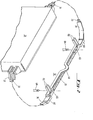
- FIG. 2 an overall perspective view of the ribbon system of the invention is shown comprising a cartridge 28 in which ribbon is supplied, a first leader 34 through which ribbon 20 is passed on its way to the print point, where it is supported by locating bridge 32, and a second leader 36 returning ribbon 20 from the vicinity of the print point to the cartridge 28.
- locating bridge means 32 is a substantially rigid member which exposes a portion of ribbon 20 so that it may be impacted by character elements 12 driven by hammer 14 so as to produce a corresponding mark on a paper 18 (FIG. 1).
- bridge means 32 is provided with an uplifted area 181 through which the hammer 14 and character element may pass on their way to impact ribbon 20.
- ribbon 20 is essentially enclosed by flexible leaders 34 and 36 while it is not stored in cartridge 28.
- Bridge means 32 is desirably provided with notches 183 designed for ready mating with pins 184 (which correspond to pins 44 in FIG. 1) which are mounted on ribbon lifter means on the typewriter so as to lift the ribbon 20 into position just prior to impact thereof by a character element. In this way, the ribbon 20 is not in the way of the view of an operator desiring to examine what has been typed.
- the bridge means 32 is provided with operator engaging finger portions 182 which are designed in such a way as to permit flexure of the bridge means 32 at a point such that the two halves of notches 183 are separated thus allowing their removal from the pins 184.
- the ends of the bridge locating means 32 are provided with attachment means 188 and 187 for attachment of the leader thereto so that a complete unit is formed.
- the cartridge 28 may similarly be provided with means for easy insertion and removal from a cartridge housing 30 (FIG. 1) so that the entire ribbon unit comprising cartridge 28, leaders 34, 36 and locating means 32 can be readily attached or removed from a typewriter.
- the leader 34 and 36 is shown as flexible at certain points.
- the design of the leaders 34 and 36 which permits this flexure is the subject matter of co-pending U.S. Patent application 61,880.
- the print point is permitted to move with respect to the cartridge 28, and the pins 184 are permitted to lift ribbon 20 into its print position.
- the locating means 32 is as exemplified by arrows allowed to move back and forth i-lith respect to a cartridge 28.
- the ribbon carried by the locating means therefor also moves, along with the print point which is exemplified by hammer 14 in FIG. 3. In this way, the bulk of the weight of ribbon 20, including ribbon housing 28 and the like is carried on the typewriter itself and is not required to move along with the print point. In this way, less total mass need be moved and therefore motion can be effected with greater speed.
- leader 36 is shown. It will be understood that leader 34 is substantially the same.
- the leader 36 may comprise a one piece extrusion of plastic material designed for flexure at certain preselected points 204.
- the leader comprises a web section 205 and enclosing sections 203 which are designed to enclose the ribbon 20 therewithin. Longitudinally extending bumps or ridges 201 may be provided in order that the ribbon 20 does not make substantial contact with the web 205 which would cause considerable friction.
- the L-shaped enclosing portions 203 are slit at predetermined intervals to provide slits 204.
- Provision of these slits 204 allows the web 205 to flex in the vicinity of the slits 204, but only in the direction such that the upstanding portions 203 do not abut. That is to say, flexure of the leader 36 is restricted to flexure away from a linear path in only one direction. In this way, the path of the ribbon 20 can be assured to be essentially circular and not take a reverse bend at any point. Thus, the inked surface of the ribbon can be prevented from contacting any part of the leader, thus preventing its being defaced.
- FIG. 5a shows one end of the locating bridge means 32 of the invention.
- the right end of the locating means 32 shown in FIG. 2 is illustrated.
- the left end is substantially similar although inverted.
- the end of the locating means 32 is formed comprising a pair of fingers 182, a notch amounting to a split ring designed to engage a pin 184, and a leader attaching portion 187.
- the ribbon 20 is passed by the leader 36 into the leader-attaching portion 187 and then passes out along the length of the ribbon locating means where it may be impacted by a character element under the action of the hammer 14.
- FIG. 5b shows a similar view of the right end of the locating means. However, it will be apparent from a comparison of FIGS.
- Locating means 32 can be made, preferably by molding, from any of a number of well-known plastic materials.
- FIG. 6 shows a cross-sectional view of the end of the locater means 187 taken along line 6-6 shown in FIG. 5b.
- a leader 36 fits snugly within the end of the locater means 187 and how the ribbon 20 is carried therewithin separated from the bulk of the leader by bumps 201. Since all the parts involved may desirably be made out of a relatively flexible plastic material it is possible to design the end of the locater means 187 and the leader 36 so that these parts are a press fit together if such is desired. In other circumstances it may be desirable to adhesively bond these parts together or to use a screw, rivet or the like.
- FIG. 7 shows a second cross-sectional view of the end of the locater means 32, this time taken along line 7-7 of FIG. 5a.
- the pin 184 may comprise a section of reduced radium 190 which may be adapted to mate with a portion of the locater means 189 of slightly narrower diameter than the larger dimension of pin 184, whereby the locater means 32 may be firmly affixed therein.
- a relatively rigid locater means with mounting structure at each end thereof permits the cartridge to be replaced without the operator having to touch the ribbon or to thread it around any guides, posts, pulleys or the like, thus avoiding any chance of causing the operator to bring his or her fingers into contact thereof and smudging the word or dirtying the typing machine.
- mounting structure such as that disclosed herein may have applicability in other related fields, such as, for example, that of magnetic tape for the storage of digital or analog data of various types.
- Such tapes are frequently very delicate and it is desirable that they be made and stored in such a way that they need not be touched by an operator to mount or dismount new tapes.
Landscapes
- Impression-Transfer Materials And Handling Thereof (AREA)
Applications Claiming Priority (2)
| Application Number | Priority Date | Filing Date | Title |
|---|---|---|---|
| US61454 | 1979-07-27 | ||
| US06/061,454 US4277187A (en) | 1979-07-27 | 1979-07-27 | Ribbon locating means |
Publications (2)
| Publication Number | Publication Date |
|---|---|
| EP0023424A2 true EP0023424A2 (fr) | 1981-02-04 |
| EP0023424A3 EP0023424A3 (fr) | 1982-05-05 |
Family
ID=22035888
Family Applications (1)
| Application Number | Title | Priority Date | Filing Date |
|---|---|---|---|
| EP80302541A Withdrawn EP0023424A3 (fr) | 1979-07-27 | 1980-07-25 | Elément de support et ensemble d'alimentation pour ruban |
Country Status (6)
| Country | Link |
|---|---|
| US (1) | US4277187A (fr) |
| EP (1) | EP0023424A3 (fr) |
| JP (1) | JPS5621883A (fr) |
| AU (1) | AU532633B2 (fr) |
| BR (1) | BR8004669A (fr) |
| CA (1) | CA1145701A (fr) |
Cited By (1)
| Publication number | Priority date | Publication date | Assignee | Title |
|---|---|---|---|---|
| US4643601A (en) * | 1984-09-28 | 1987-02-17 | International Business Machines Corporation | Ribbon positioning mechanism |
Families Citing this family (8)
| Publication number | Priority date | Publication date | Assignee | Title |
|---|---|---|---|---|
| US4388006A (en) * | 1981-03-03 | 1983-06-14 | Durango Systems, Inc. | Printing ribbon cartridge |
| JPS5829447U (ja) * | 1981-08-21 | 1983-02-25 | セイコーエプソン株式会社 | 印字装置 |
| US4469456A (en) * | 1981-09-25 | 1984-09-04 | Fitzgerald H Diane | Disposable ribbon carrier for a stenograph reporting machine |
| US4437779A (en) | 1981-12-29 | 1984-03-20 | International Business Machines Corporation | Replaceable ribbon cartridge |
| US4486107A (en) * | 1982-09-24 | 1984-12-04 | Willcox Frederick P | Ribbon guiding and directing structure and cartridge |
| US4632583A (en) * | 1984-10-01 | 1986-12-30 | International Business Machines Corporation | Flexible leader |
| EP0225498B1 (fr) * | 1985-12-11 | 1993-09-22 | International Business Machines Corporation | Assemblage d'imprimante à ruban encreur avec une protection intégrale de ruban encreur et méthode d'impression de document |
| US4773779A (en) * | 1985-12-11 | 1988-09-27 | International Business Machines Corporation | Printer ribbon cartridge with flexible ribbon guides and integral ribbon shield |
Family Cites Families (5)
| Publication number | Priority date | Publication date | Assignee | Title |
|---|---|---|---|---|
| CH536383A (fr) * | 1971-04-08 | 1973-04-30 | Stalder Fred | Pince à linge |
| US3986593A (en) * | 1975-05-14 | 1976-10-19 | Pitney-Bowes, Inc. | Snap-action fastener assembly |
| US4047608A (en) * | 1976-04-01 | 1977-09-13 | Willcox Frederick P | Compliant ribbon-guiding structure |
| US4203676A (en) * | 1977-09-14 | 1980-05-20 | Exxon Research & Engineering Co. | Ribbon mounting apparatus |
| DE2826751A1 (de) * | 1978-06-19 | 1979-12-20 | Olympia Werke Ag | Typenhebelschreibmaschine mit einer aufnahmevorrichtung fuer eine farbbandkassette |
-
1979
- 1979-07-27 US US06/061,454 patent/US4277187A/en not_active Expired - Lifetime
-
1980
- 1980-05-09 CA CA000351656A patent/CA1145701A/fr not_active Expired
- 1980-07-25 AU AU60798/80A patent/AU532633B2/en not_active Ceased
- 1980-07-25 EP EP80302541A patent/EP0023424A3/fr not_active Withdrawn
- 1980-07-25 BR BR8004669A patent/BR8004669A/pt unknown
- 1980-07-28 JP JP10256880A patent/JPS5621883A/ja active Pending
Cited By (1)
| Publication number | Priority date | Publication date | Assignee | Title |
|---|---|---|---|---|
| US4643601A (en) * | 1984-09-28 | 1987-02-17 | International Business Machines Corporation | Ribbon positioning mechanism |
Also Published As
| Publication number | Publication date |
|---|---|
| AU6079880A (en) | 1981-01-29 |
| AU532633B2 (en) | 1983-10-06 |
| CA1145701A (fr) | 1983-05-03 |
| BR8004669A (pt) | 1981-02-10 |
| EP0023424A3 (fr) | 1982-05-05 |
| JPS5621883A (en) | 1981-02-28 |
| US4277187A (en) | 1981-07-07 |
Similar Documents
| Publication | Publication Date | Title |
|---|---|---|
| CA1145701A (fr) | Mecanisme d'entrainement de ruban d'impression | |
| EP0168193B1 (fr) | Cartouche pour ruban encreur | |
| CA1144506A (fr) | Amorce souple, et methode de faconnage connexe | |
| US4406553A (en) | Disposable, snap-in-type ribbon cassette having a resilient ribbon spool mounting arm | |
| US4623273A (en) | Cartridge for a ribbon for typewriters | |
| KR960000968B1 (ko) | 전사식 프린터 | |
| US4496256A (en) | Impact printing apparatus | |
| US4203676A (en) | Ribbon mounting apparatus | |
| US4798486A (en) | Ink ribbon cassette having mounting means, slack preventing means and multiple ribbon shifting means | |
| FR2346161A1 (fr) | Systeme de cassettes pour ruban de machine a ecrire ou a imprimer | |
| US4202639A (en) | Daisy loading apparatus | |
| EP0004047B1 (fr) | Cartouche pour rubans encreurs | |
| EP0021737B1 (fr) | Procédé et dispositif pour maintenir la tension d'un ruban et son application à une machine à écrire | |
| US4838718A (en) | Printing device | |
| EP0176733B1 (fr) | Elément de guidage flexible | |
| EP0028873A2 (fr) | Dispositif d'alimentation et de mise sous tension du ruban, et imprimante comportant ce dispositif | |
| US4290704A (en) | Flexible ribbon guide means | |
| EP0169197A4 (fr) | Cassette a ruban. | |
| US4173183A (en) | Line printer character belt | |
| CA1167796A (fr) | Support de materiau de correction que l'on peut positionner manuellement et distributeur | |
| JPS5884787A (ja) | リボンカセツト | |
| EP0041183B1 (fr) | Etiqueteuse à main | |
| GB1604301A (en) | Printer ribbon arrangement | |
| JPS6334938Y2 (fr) | ||
| US5516217A (en) | Document guiding ribbon cartridge |
Legal Events
| Date | Code | Title | Description |
|---|---|---|---|
| PUAI | Public reference made under article 153(3) epc to a published international application that has entered the european phase |
Free format text: ORIGINAL CODE: 0009012 |
|
| AK | Designated contracting states |
Designated state(s): BE CH DE FR GB IT |
|
| 17P | Request for examination filed |
Effective date: 19810717 |
|
| PUAL | Search report despatched |
Free format text: ORIGINAL CODE: 0009013 |
|
| AK | Designated contracting states |
Designated state(s): BE CH DE FR GB IT |
|
| STAA | Information on the status of an ep patent application or granted ep patent |
Free format text: STATUS: THE APPLICATION HAS BEEN WITHDRAWN |
|
| 18W | Application withdrawn |
Withdrawal date: 19820804 |
|
| RIN1 | Information on inventor provided before grant (corrected) |
Inventor name: RELLO, MICHAEL JOSEPH |