EP0023629A1 - Dispositif pour régler par zone l'application d'eau de mouillage - Google Patents
Dispositif pour régler par zone l'application d'eau de mouillage Download PDFInfo
- Publication number
- EP0023629A1 EP0023629A1 EP80104138A EP80104138A EP0023629A1 EP 0023629 A1 EP0023629 A1 EP 0023629A1 EP 80104138 A EP80104138 A EP 80104138A EP 80104138 A EP80104138 A EP 80104138A EP 0023629 A1 EP0023629 A1 EP 0023629A1
- Authority
- EP
- European Patent Office
- Prior art keywords
- zone
- dampening solution
- ink
- dampening
- amount
- Prior art date
- Legal status (The legal status is an assumption and is not a legal conclusion. Google has not performed a legal analysis and makes no representation as to the accuracy of the status listed.)
- Granted
Links
Images




Classifications
-
- B—PERFORMING OPERATIONS; TRANSPORTING
- B41—PRINTING; LINING MACHINES; TYPEWRITERS; STAMPS
- B41F—PRINTING MACHINES OR PRESSES
- B41F31/00—Inking arrangements or devices
- B41F31/007—Removing water from ink trains
-
- B—PERFORMING OPERATIONS; TRANSPORTING
- B41—PRINTING; LINING MACHINES; TYPEWRITERS; STAMPS
- B41F—PRINTING MACHINES OR PRESSES
- B41F33/00—Indicating, counting, warning, control or safety devices
- B41F33/0054—Devices for controlling dampening
Definitions
- the invention relates to a device for zonal regulation of the dampening solution guidance over the width of the printing form of an offset printing machine with actuators for zone-wise ink metering.
- This local dampening solution management is partly achieved by metering the amount of dampening solution supplied, e.g. made in the contactless dampening systems (DE-PS 24 39 999 and DE-PS 20 58 667), but also partly by locally blowing off or scraping off the amount of dampening solution supplied on a dampening roller, which also includes ink rollers.
- the invention has for its object to influence the mechanical dampening solution guide so that the tolerance range between the so-called smear limit - too little water - and the water mark limit - too much water - is significantly expanded. Furthermore, with the optimal pressure conditions, which are close to the lubrication limit of certain zones, an increase in quality should be achieved for all zones. It is based on the knowledge that there is a certain relationship between the metered amount of ink and the amount of fountain solution required under the same printing conditions.
- the variation of the duct rotation angle and metering via zonal actuators are available for both media.
- the zonal adjustment device is to be used for the subject of the shape, for the subject-independent parameters, e.g. Machine speed, room temperature etc., it is advisable to change the zonal independent control element (e.g. duct speed, color strip width, metering valve for contactless dampening systems etc.).
- the device for zonal dampening solution guidance over the width of the printing form of an offset printing machine is characterized in that the actuators for the zone-wise ink metering are assigned corresponding actuators for the dampening solution guidance and these are coupled to one another, with the inclusion of a transmission characteristic which influences the zonal ink / dampening solution equilibrium Adapting element taking parameters into account.
- the measures according to the invention clearly assign the dampening solution amount zonally to the amount of ink according to a specific, generally non-linear characteristic.
- the characteristic curve is set according to the water absorption capacity of the paint with optimal use of the area between the water marks and the smear limit using the adapter.
- the printer then only has to operate the zonal color actuator, if an appropriate, generally medium basic setting of the ink and dampener rotation angle has been made beforehand. The correct zonal allocation of the amount of dampening solution is then inevitably done without the addition of the printer.
- the exemplary embodiments shown always relate to a zonally assigned unit.
- a wet zone is directly assigned to each ink zone, the width of a wet or ink zone corresponding to the distance between the ink control elements.
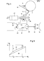
- FIG. 1 shows a side view of an offset printing unit, in which the sheets to be printed are passed between printing cylinder 1 and blanket cylinder 2 in a known manner.
- the rubber cylinder 2 works together with a plate cylinder 3 which is provided with dampening solution and ink by a dampening unit 4 and an inking unit 5.
- the structure of the dampening and inking unit corresponds to a modern design, the dampening solution being fed from a dampening roller 6 and the ink from an ink fountain roller 7 to the rollers of the dampening inking unit.
- the dampening roller 6 is immersed in dampening solution 8 and the ink fountain roller 7 receives the ink 9 from an ink fountain 10.
- a number of inking cylinders 11 are provided on the ink fountain 10 parallel to the ink fountain roller 7, which can be adjusted by means of adjusting screws 12.
- devices e.g. in the form of a centrifugal blower 13, as in the embodiment shown in Figure 1, either in front of the inking roller 14 or on other, e.g. the rollers marked with an arrow are arranged by the dampening inking unit.
- the inking cylinders 11 are adjusted via the lever gear 16 in such a way that more or less ink 9 can be given to the inking unit 5 through the ink fountain roller 7 through the curved channels in the inking cylinders 11.
- a color setting cylinder 11 is provided for each color zone of approximately 30 mm in width.
- the lever gear 16 is gem.
- Fig.2 a pivotable blow pipe 17 coupled to the adjusting nut 15, so that Simultaneously with the adjustment of the ink supply via the lever gear 24, there is a change in the blowing angle of the blowing tube 17 onto an inking roller 14.
- the inking roller 14 also carries fountain solution.
- the proportion of dampening water in the relevant zone of the blown ink roller 14 is changed depending on the angle of attack of the blowpipe 17 and the intensity of the air supply.
- the supply line 18 supplies all blow pipes 17 arranged for each zone at the same time via separate hoses 19.
- a valve 20 acting as an adapter in front of the supply line 18 the dependency of the quantity of dampening solution blown off on the quantity of ink supplied can be changed in its quantity allocation depending on the factors influencing the quantity of water.
- the pivotable blowpipes 17 are mounted in a bearing part 21 common to all blowpipes.
- the embodiment shown in FIG. 3 includes, instead of the pivotable blowpipes 17, the fixed blowpipes 22, which are rigidly connected to the valve body 23 and directed towards the fountain roller-carrying ink roller 14.
- the coupling with the color control system takes place via the lever gear 24, a different valve opening being set depending on the position of the color control screws 12.
- the embodiment shown in Figure 4 is a coupling of the zonal ink and zonal fountain solution control elements, e.g. of centrifugal blowers 13 for blowing off excess dampening solution by means of electrical components.
- the adjusting nut 15 for each zone, the adjusting screw 12 of which in the example shown is driven by a servomotor 27, is connected to the sliding contact 28 of a variable electrical resistor 29.
- the armature voltage supplied to the direct current motor 30 is adjusted depending on the position of the sliding contact 28, as a result of which the blower motor speed and thus the amount of blown air supplied is achieved with the color control cylinder 11.
- the excitation current in the excitation winding 31 is adjustable by the variable resistor 32.
- the variable resistor 32 serves as Adapter.
- the DC motor 30 can be operated either as a separately excited motor or as a shunt motor.
- the adaptation via the variable resistor 32 brings about a more or less linear adaptation.
- a shunt motor there is a non-linear adaptation possibility when the excitation winding 31 is operated in the area of the non-linear magnetization.
- FIG. 5 shows the relationship between the ink actuator opening X and the required amount of water Q in a diagram as an example without any claim to quantitative validity.
- the ink setting cylinder opening is shown on the abscissa of the diagram, and the amount of dampening solution to be assigned zonally is shown on the ordinate.
- the straight line 36 represents a strongly idealized connection; curve 37 shows an assumed actual relationship of the quantity ratios to be determined by experiment.
- a quantity of water Y1 and Y2 must be drained off at the inking cylinder openings X1 and X2 if, regardless of the inking cylinder opening, e.g. through the dampening roller 6, a constant amount of dampening solution Qo is supplied.
- Figure 6 shows a block diagram.
- the first block 38 represents a measuring element which determines the position of the inking cylinder 11 in zones.
- the second block 39 represents an electronic computing unit which, in accordance with the characteristic curve shown in this block, brings about the relationship between the values X and Y of the diagram in FIG. 5.
- the characteristic Z can be used to influence the characteristic (curves with parameters Z1 or Z2). This system applies e.g. for a blow-off device by means of a fan 13.
- FIG. 7 shows a modification of FIG. 6 in such a way that the size Y corresponds to the degree of opening of the aperture 40 of a dampening solution spraying unit 41.
- the input variable X of the electronic computing unit 43 corresponds to the zonal color quantity, the input variable Z to the adaptation.
- the computing units 39 and 43 are elements or components known from electronics or control technology. Microprocessors can also be used for this.
- FIG. 8 shows schematically once again a blow-off device for blowing off too much conveyed dampening solution by means of a centrifugal fan 13.
- the blow-off is provided directly on a dampening roller 44.
- FIG. 9 schematically shows a similar device in which the centrifugal fan 13 is replaced by an air nozzle 45.
- FIG. 10 schematically shows a device for the evaporation of excess moisture delivered by an electrical resistance heater 46.
- FIG. 11 shows a similar device in which infrared light from a lamp 47 is used instead of the resistance heater 46 to evaporate too much water that has been pumped.
- FIG. 12 shows schematically the application of the invention according to FIG. 7 by means of a spray or brush dampening unit 48.
- the amount of dampening solution supplied can be regulated via the orifice 40 and the adjusting means 49.
- FIG. 13 shows the application in a centrifugal dampening unit 50, the amount of dampening solution being regulated by means of motorized adjustment by means of valves (not shown) in the dampening solution supply.
Landscapes
- Inking, Control Or Cleaning Of Printing Machines (AREA)
- Rotary Presses (AREA)
Priority Applications (1)
| Application Number | Priority Date | Filing Date | Title |
|---|---|---|---|
| AT80104138T ATE2407T1 (de) | 1979-08-03 | 1980-07-16 | Einrichtung zur zonalen regulierung der feuchtmittelfuehrung. |
Applications Claiming Priority (2)
| Application Number | Priority Date | Filing Date | Title |
|---|---|---|---|
| DE2931579 | 1979-08-03 | ||
| DE2931579A DE2931579C2 (de) | 1979-08-03 | 1979-08-03 | Einrichtung zur zonalen Regulierung der Feuchtmittelführung |
Publications (2)
| Publication Number | Publication Date |
|---|---|
| EP0023629A1 true EP0023629A1 (fr) | 1981-02-11 |
| EP0023629B1 EP0023629B1 (fr) | 1983-02-09 |
Family
ID=6077584
Family Applications (1)
| Application Number | Title | Priority Date | Filing Date |
|---|---|---|---|
| EP80104138A Expired EP0023629B1 (fr) | 1979-08-03 | 1980-07-16 | Dispositif pour régler par zone l'application d'eau de mouillage |
Country Status (4)
| Country | Link |
|---|---|
| EP (1) | EP0023629B1 (fr) |
| JP (2) | JPS5624166A (fr) |
| AT (1) | ATE2407T1 (fr) |
| DE (1) | DE2931579C2 (fr) |
Cited By (7)
| Publication number | Priority date | Publication date | Assignee | Title |
|---|---|---|---|---|
| EP0090181A1 (fr) * | 1982-03-26 | 1983-10-05 | M.A.N.-ROLAND Druckmaschinen Aktiengesellschaft | Procédé et dispositif de mouillage de plaques d'impression |
| EP0116139A1 (fr) * | 1982-12-23 | 1984-08-22 | Heidelberger Druckmaschinen Aktiengesellschaft | Dispositif de réglage du mouillage en fonction du profil d'encrage dans le dispositif d'encrage des machines d'impression offset |
| EP0591986A1 (fr) * | 1992-10-09 | 1994-04-13 | Komori Corporation | Dispositif pour extraire le mouillage dans une presse à imprimer |
| WO1996016806A1 (fr) * | 1994-11-25 | 1996-06-06 | Brepols N.V. | Procede et dispositif d'indication de rebuts dans une presse rotative appliquant un procede lithographique |
| EP0941847A1 (fr) * | 1998-03-13 | 1999-09-15 | Heidelberger Druckmaschinen Aktiengesellschaft | Dispositif et procédé de dosage de l'encre dans des machines à imprimer offset |
| DE102009052094A1 (de) | 2008-12-05 | 2010-06-10 | Heidelberger Druckmaschinen Ag | Verfahren zur Feuchtmittelsteuerung in einer Druckmaschine |
| DE10152466B4 (de) * | 2000-11-24 | 2015-12-17 | Heidelberger Druckmaschinen Ag | Feuchteregelung unter Berücksichtigung mehrerer den Druckprozess beeinflussender Größen |
Families Citing this family (27)
| Publication number | Priority date | Publication date | Assignee | Title |
|---|---|---|---|---|
| DE3203500C2 (de) * | 1982-02-03 | 1988-03-03 | Heidelberger Druckmaschinen Ag, 6900 Heidelberg | Farbmesser und eine Einstellvorrichtung für ein Farbmesser |
| JPS58132561A (ja) * | 1982-02-03 | 1983-08-06 | Toppan Printing Co Ltd | インキ及び湿し水の供給方法 |
| JPS58132560A (ja) * | 1982-02-03 | 1983-08-06 | Toppan Printing Co Ltd | インキ及び湿し水の供給方法 |
| JPS58145453A (ja) * | 1982-02-24 | 1983-08-30 | Toppan Printing Co Ltd | インキ及び湿し水の供給方法及び装置 |
| JPS58153655A (ja) * | 1982-03-10 | 1983-09-12 | Toppan Printing Co Ltd | インキ及び湿し水の供給方法及び装置 |
| DE3220701C3 (de) * | 1982-06-02 | 1995-09-07 | Heidelberger Druckmasch Ag | Vorrichtung zur Feuchtmittelführung bei einem Offsetdruckwerk |
| AT389675B (de) * | 1982-06-02 | 1990-01-10 | Heidelberger Druckmasch Ag | Vorrichtung zur farbprofilabhaengigen feuchtmittelregelung |
| JPS5990446U (ja) * | 1982-12-07 | 1984-06-19 | 三菱重工業株式会社 | オフセツト印刷機のインキ装置 |
| JPS60120054A (ja) * | 1983-11-30 | 1985-06-27 | ミルトン・レイ・レマスター | 印刷機インキ装置の脱水装置および方法 |
| JPS6179656A (ja) * | 1984-09-28 | 1986-04-23 | Dainippon Printing Co Ltd | オフセツト印刷機 |
| DD253679A1 (de) * | 1986-11-13 | 1988-01-27 | Polygraph Leipzig | Verfahren zum regeln der farbdichte |
| DE3725971A1 (de) * | 1987-08-05 | 1989-02-16 | Helmut Prof Dr Ing Rech | Feuchtmittelsperre zur leistungssteigerung des offsetdruckverfahrens |
| DE3907584A1 (de) * | 1989-03-09 | 1990-09-13 | Heidelberger Druckmasch Ag | Verfahren zur feuchteregelung bei einer offsetdruckmaschine |
| JPH0745245B2 (ja) * | 1991-06-28 | 1995-05-17 | 株式会社東京機械製作所 | 平版印刷方法及び平版印刷装置 |
| DE4125012A1 (de) * | 1991-07-27 | 1993-01-28 | Koenig & Bauer Ag | Einrichtung zum befeuchten von zylindern bei offsetrotationsdruckmaschinen |
| DE4206525C2 (de) * | 1992-03-02 | 2001-05-17 | Heidelberger Druckmasch Ag | Vorrichtung zur Beeinflussung einer Feuchtmittelverteilung in einem Druckwerk einer Druckmaschine |
| DE4436582C2 (de) * | 1994-10-13 | 1998-07-30 | Heidelberger Druckmasch Ag | Verfahren zur Regelung einer Feuchtmittelmenge für eine Druckform einer laufenden Offsetrotationsdruckmaschine |
| DE19643353A1 (de) * | 1996-10-21 | 1998-04-23 | Heidelberger Druckmasch Ag | Vorrichtung zur Dosierung von Flüssigkeiten |
| DE19838020A1 (de) * | 1997-09-15 | 1999-03-18 | Roland Man Druckmasch | Vorrichtung zum Auftragen von Feuchtmittel auf den Zylinder einer Rotationsdruckmaschine |
| DE10058550A1 (de) | 2000-11-24 | 2002-05-29 | Heidelberger Druckmasch Ag | Verfahren zur Regelung des Farb-zu-Feuchtmittelgleichgewichts in einer Rotations-Offsetdruckmaschine |
| DE102007028969A1 (de) * | 2007-06-23 | 2008-12-24 | Manroland Ag | Verfahren zur Ermittlung eines Stellsignals für Farbzonenstellelemente eines Farbwerks oder für Feuchtmitteldosiereinrichtungen eines Feuchtwerks |
| JP5069523B2 (ja) * | 2007-08-31 | 2012-11-07 | 株式会社加貫ローラ製作所 | オフセット印刷機の給水装置 |
| DE102007042458A1 (de) * | 2007-09-06 | 2009-03-12 | Manroland Ag | Druckwerk einer Druckmaschine |
| DE102009040057A1 (de) | 2008-09-18 | 2010-04-01 | Heidelberger Druckmaschinen Ag | Feuchtwerk einer Druckmaschine |
| DE102014218452A1 (de) | 2014-09-15 | 2016-04-07 | Koenig & Bauer Ag | Vorrichtungen und Verfahren zur Einstellung und/oder Änderung eines sich in Richtung Druckbreite erstreckenden Profils in der Feuchtmittelführung sowie Druckwerk mit einer Vorrichtung zur Einstellung und/oder Änderung des Profils |
| JP6297214B2 (ja) * | 2014-09-15 | 2018-03-20 | ケーニッヒ ウント バウアー アー・ゲーKoenig & Bauer AG | 印刷部の湿し媒体案内におけるプロフィールの調整および/または変更 |
| DE102014218451B4 (de) | 2014-09-15 | 2018-05-03 | Koenig & Bauer Ag | Vorrichtungen und Verfahren zur Einstellung und/oder Änderung eines sich in Richtung Druckbreite erstreckenden Profils in der Feuchtmittelführung sowie Druckwerk mit einer Vorrichtung zur Einstellung und/oder Änderung des Profils |
Citations (1)
| Publication number | Priority date | Publication date | Assignee | Title |
|---|---|---|---|---|
| US2546793A (en) * | 1946-02-16 | 1951-03-27 | Joseph E Sodomka | Moisture removing means for the inker of lithographic presses and the like |
Family Cites Families (8)
| Publication number | Priority date | Publication date | Assignee | Title |
|---|---|---|---|---|
| DE1268154B (de) * | 1966-03-22 | 1968-05-16 | Planeta Veb Druckmasch Werke | Feuchtwerk fuer Offsetdruckmaschinen |
| DE1944831A1 (de) * | 1969-09-04 | 1971-03-11 | Rowecki Norbert Dipl Kfm | Eisenbahnwagen mit drehbarer Plattform fuer den Transport von Strassenfahrzeugen im Huckepackverkehr |
| DE6948111U (de) * | 1969-12-12 | 1972-05-10 | Koenig & Bauer Schnellpressfab | Filmfeuchtwerk fuer offsetdruckmaschinen. |
| DE2058667B1 (de) * | 1970-11-28 | 1972-05-25 | Weitmann & Konrad | Vorrichtung in Druckereimaschinen,insbesondere Offsetmaschinen,zum Aufbringen von Fluessigkeit auf bewegte Flaechen |
| DE2214721B1 (de) * | 1972-03-25 | 1973-06-14 | Heidelberger Druckmaschinen Ag, 6900 Heidelberg | Verfahren und vorrichtung zum selbsttaetigen ausregeln von schwankungen der farb- und feuchtfluessigkeitsfuehrung an offsetmaschinen |
| FR2178802B2 (fr) * | 1972-04-07 | 1974-08-02 | Uniroyal | |
| DE2648098C3 (de) * | 1976-10-23 | 1984-01-05 | Heidelberger Druckmaschinen Ag, 6900 Heidelberg | Farbkasten für Offset- oder Hochdruckmaschinen |
| US4157682A (en) * | 1977-08-01 | 1979-06-12 | Am International, Inc. | Ink and moisture control system with run-length compensation |
-
1979
- 1979-08-03 DE DE2931579A patent/DE2931579C2/de not_active Expired
-
1980
- 1980-07-16 AT AT80104138T patent/ATE2407T1/de not_active IP Right Cessation
- 1980-07-16 EP EP80104138A patent/EP0023629B1/fr not_active Expired
- 1980-07-31 JP JP10444880A patent/JPS5624166A/ja active Pending
-
1985
- 1985-09-17 JP JP1985140804U patent/JPS6164446U/ja active Pending
Patent Citations (1)
| Publication number | Priority date | Publication date | Assignee | Title |
|---|---|---|---|---|
| US2546793A (en) * | 1946-02-16 | 1951-03-27 | Joseph E Sodomka | Moisture removing means for the inker of lithographic presses and the like |
Cited By (8)
| Publication number | Priority date | Publication date | Assignee | Title |
|---|---|---|---|---|
| EP0090181A1 (fr) * | 1982-03-26 | 1983-10-05 | M.A.N.-ROLAND Druckmaschinen Aktiengesellschaft | Procédé et dispositif de mouillage de plaques d'impression |
| EP0116139A1 (fr) * | 1982-12-23 | 1984-08-22 | Heidelberger Druckmaschinen Aktiengesellschaft | Dispositif de réglage du mouillage en fonction du profil d'encrage dans le dispositif d'encrage des machines d'impression offset |
| EP0591986A1 (fr) * | 1992-10-09 | 1994-04-13 | Komori Corporation | Dispositif pour extraire le mouillage dans une presse à imprimer |
| US5388512A (en) * | 1992-10-09 | 1995-02-14 | Komori Corporation | Dampening suppression apparatus for printing press |
| WO1996016806A1 (fr) * | 1994-11-25 | 1996-06-06 | Brepols N.V. | Procede et dispositif d'indication de rebuts dans une presse rotative appliquant un procede lithographique |
| EP0941847A1 (fr) * | 1998-03-13 | 1999-09-15 | Heidelberger Druckmaschinen Aktiengesellschaft | Dispositif et procédé de dosage de l'encre dans des machines à imprimer offset |
| DE10152466B4 (de) * | 2000-11-24 | 2015-12-17 | Heidelberger Druckmaschinen Ag | Feuchteregelung unter Berücksichtigung mehrerer den Druckprozess beeinflussender Größen |
| DE102009052094A1 (de) | 2008-12-05 | 2010-06-10 | Heidelberger Druckmaschinen Ag | Verfahren zur Feuchtmittelsteuerung in einer Druckmaschine |
Also Published As
| Publication number | Publication date |
|---|---|
| JPS6164446U (fr) | 1986-05-01 |
| JPS5624166A (en) | 1981-03-07 |
| DE2931579A1 (de) | 1981-02-05 |
| EP0023629B1 (fr) | 1983-02-09 |
| DE2931579C2 (de) | 1982-11-11 |
| ATE2407T1 (de) | 1983-03-15 |
Similar Documents
| Publication | Publication Date | Title |
|---|---|---|
| EP0023629B1 (fr) | Dispositif pour régler par zone l'application d'eau de mouillage | |
| DE19822662C2 (de) | Verfahren zur Farbreproduktion auf einer Bilddaten orientierten Druckmaschine | |
| DE2728738A1 (de) | Einrichtung zur kontrolle und regelung des druckvorgangs an druckmaschinen | |
| DE102007008392B4 (de) | Integrierte Qualitätsregelung | |
| DE19720954C2 (de) | Verfahren zum Einrichten der Farbführung im Fortdruck in einer Rotationsdruckmaschine | |
| EP1142711B1 (fr) | Machine d' impression avec une commande pour un système de séchage | |
| DE10103039A1 (de) | Verfahren zur Einstellung drucktechnischer und anderer jobabhängiger Parameter einer Druckmaschine | |
| DE4214139C2 (de) | Verfahren zur Feuchtmittelregulierung beim Drucken von einem Formzylinder in einer Offsetdruckmaschine | |
| WO2005115758A1 (fr) | Procede et dispositif pour reguler un transfert d'encre, et procede pour se servir de ce dispositif | |
| DE10245702A1 (de) | Anpassung der Farbsteuerung an die physikalischen Eigenschaften von Farbe und Bedruckstoff | |
| EP1167033B1 (fr) | Procédé de préréglage et système de commande d'un dispositif d'encrage | |
| EP0090181A1 (fr) | Procédé et dispositif de mouillage de plaques d'impression | |
| DE3326698A1 (de) | Vorrichtung zur zonenweisen messtechnischen kontrolle der feuchtmittelfuehrung im druckwerk einer offsetdruckmaschine | |
| DE3204501C1 (de) | Vorrichtung zur Regelung der Farbzufuehrung in einer Rotationsdruckmaschine | |
| US20010002577A1 (en) | Method for controlling a quantity of ink in a printing machine | |
| EP1216833B1 (fr) | Méthode de régulation de l'équilibre encre-solution de mouillage dans une machine d'impression rotative | |
| DE102012012517B4 (de) | Feuchtmittelregelung in einer Druckmaschine | |
| EP0634271A1 (fr) | Méthode et dispositif pour régler la température d'une encre dans l'unité d'encrage d'une machine d'imprimerie | |
| DE102007011344A1 (de) | Verfahren zur Farbmessung bei Druckmaschinen | |
| EP0116139B1 (fr) | Dispositif de réglage du mouillage en fonction du profil d'encrage dans le dispositif d'encrage des machines d'impression offset | |
| DE2945894C2 (de) | Farbkastenwalzenantriebseinrichtung eines Farbwerkes für Druckmaschinen | |
| DE102007063852B3 (de) | Integrierte Qualitätsregelung | |
| DE102012016832A1 (de) | Farbregelung auf letzter Farbauftragswalze | |
| DE4300071C2 (de) | Verfahren zur Steuerung einer Farbführung in einem Druckwerk einer Druckmaschine | |
| EP2168768A2 (fr) | Imprimante offset |
Legal Events
| Date | Code | Title | Description |
|---|---|---|---|
| PUAI | Public reference made under article 153(3) epc to a published international application that has entered the european phase |
Free format text: ORIGINAL CODE: 0009012 |
|
| AK | Designated contracting states |
Designated state(s): AT CH FR GB IT SE |
|
| 17P | Request for examination filed |
Effective date: 19810304 |
|
| ITF | It: translation for a ep patent filed | ||
| GRAA | (expected) grant |
Free format text: ORIGINAL CODE: 0009210 |
|
| AK | Designated contracting states |
Designated state(s): AT CH FR GB IT LI SE |
|
| REF | Corresponds to: |
Ref document number: 2407 Country of ref document: AT Date of ref document: 19830315 Kind code of ref document: T |
|
| ET | Fr: translation filed | ||
| PGFP | Annual fee paid to national office [announced via postgrant information from national office to epo] |
Ref country code: CH Payment date: 19840615 Year of fee payment: 5 |
|
| PGFP | Annual fee paid to national office [announced via postgrant information from national office to epo] |
Ref country code: AT Payment date: 19860630 Year of fee payment: 7 |
|
| PG25 | Lapsed in a contracting state [announced via postgrant information from national office to epo] |
Ref country code: AT Effective date: 19890716 |
|
| PG25 | Lapsed in a contracting state [announced via postgrant information from national office to epo] |
Ref country code: LI Effective date: 19890731 Ref country code: CH Effective date: 19890731 |
|
| REG | Reference to a national code |
Ref country code: CH Ref legal event code: PL |
|
| PGFP | Annual fee paid to national office [announced via postgrant information from national office to epo] |
Ref country code: FR Payment date: 19920707 Year of fee payment: 13 |
|
| PGFP | Annual fee paid to national office [announced via postgrant information from national office to epo] |
Ref country code: SE Payment date: 19920715 Year of fee payment: 13 |
|
| PG25 | Lapsed in a contracting state [announced via postgrant information from national office to epo] |
Ref country code: SE Effective date: 19930717 |
|
| PG25 | Lapsed in a contracting state [announced via postgrant information from national office to epo] |
Ref country code: FR Effective date: 19940331 |
|
| REG | Reference to a national code |
Ref country code: FR Ref legal event code: ST |
|
| EUG | Se: european patent has lapsed |
Ref document number: 80104138.5 Effective date: 19940210 |
|
| PGFP | Annual fee paid to national office [announced via postgrant information from national office to epo] |
Ref country code: GB Payment date: 19950616 Year of fee payment: 16 |
|
| PG25 | Lapsed in a contracting state [announced via postgrant information from national office to epo] |
Ref country code: GB Effective date: 19960716 |
|
| GBPC | Gb: european patent ceased through non-payment of renewal fee |
Effective date: 19960716 |
|
| PLBE | No opposition filed within time limit |
Free format text: ORIGINAL CODE: 0009261 |
|
| STAA | Information on the status of an ep patent application or granted ep patent |
Free format text: STATUS: NO OPPOSITION FILED WITHIN TIME LIMIT |