EP0023732A1 - Kapazitive Sonde - Google Patents
Kapazitive Sonde Download PDFInfo
- Publication number
- EP0023732A1 EP0023732A1 EP80200660A EP80200660A EP0023732A1 EP 0023732 A1 EP0023732 A1 EP 0023732A1 EP 80200660 A EP80200660 A EP 80200660A EP 80200660 A EP80200660 A EP 80200660A EP 0023732 A1 EP0023732 A1 EP 0023732A1
- Authority
- EP
- European Patent Office
- Prior art keywords
- electrode
- sub
- electrodes
- capacitor
- gauge
- Prior art date
- Legal status (The legal status is an assumption and is not a legal conclusion. Google has not performed a legal analysis and makes no representation as to the accuracy of the status listed.)
- Granted
Links
- 239000003990 capacitor Substances 0.000 claims abstract description 96
- 238000005259 measurement Methods 0.000 claims description 39
- 230000008030 elimination Effects 0.000 claims description 14
- 238000003379 elimination reaction Methods 0.000 claims description 14
- 239000012528 membrane Substances 0.000 claims description 8
- 238000005303 weighing Methods 0.000 claims description 4
- 230000007935 neutral effect Effects 0.000 claims 2
- 238000000926 separation method Methods 0.000 abstract description 2
- 239000000969 carrier Substances 0.000 description 25
- 230000000694 effects Effects 0.000 description 9
- 238000006073 displacement reaction Methods 0.000 description 8
- 238000010276 construction Methods 0.000 description 7
- 230000035945 sensitivity Effects 0.000 description 7
- 238000013519 translation Methods 0.000 description 7
- 230000014616 translation Effects 0.000 description 7
- 238000012937 correction Methods 0.000 description 6
- 238000011835 investigation Methods 0.000 description 6
- 239000000463 material Substances 0.000 description 6
- 239000011159 matrix material Substances 0.000 description 5
- 238000001514 detection method Methods 0.000 description 4
- 239000012774 insulation material Substances 0.000 description 4
- 230000009897 systematic effect Effects 0.000 description 4
- 238000005452 bending Methods 0.000 description 3
- 239000011521 glass Substances 0.000 description 3
- 230000005484 gravity Effects 0.000 description 3
- 230000006872 improvement Effects 0.000 description 3
- 238000000034 method Methods 0.000 description 3
- 230000003071 parasitic effect Effects 0.000 description 3
- 238000007665 sagging Methods 0.000 description 3
- RZVAJINKPMORJF-UHFFFAOYSA-N Acetaminophen Chemical compound CC(=O)NC1=CC=C(O)C=C1 RZVAJINKPMORJF-UHFFFAOYSA-N 0.000 description 2
- 230000008901 benefit Effects 0.000 description 2
- 230000015572 biosynthetic process Effects 0.000 description 2
- 230000008859 change Effects 0.000 description 2
- 238000000576 coating method Methods 0.000 description 2
- 230000007423 decrease Effects 0.000 description 2
- 239000012212 insulator Substances 0.000 description 2
- 229910052751 metal Inorganic materials 0.000 description 2
- 239000002184 metal Substances 0.000 description 2
- 230000008569 process Effects 0.000 description 2
- 238000012545 processing Methods 0.000 description 2
- 239000005297 pyrex Substances 0.000 description 2
- 230000003213 activating effect Effects 0.000 description 1
- 229910052782 aluminium Inorganic materials 0.000 description 1
- XAGFODPZIPBFFR-UHFFFAOYSA-N aluminium Chemical compound [Al] XAGFODPZIPBFFR-UHFFFAOYSA-N 0.000 description 1
- 239000012876 carrier material Substances 0.000 description 1
- 239000000919 ceramic Substances 0.000 description 1
- 239000011248 coating agent Substances 0.000 description 1
- 239000002131 composite material Substances 0.000 description 1
- 230000001276 controlling effect Effects 0.000 description 1
- 230000002596 correlated effect Effects 0.000 description 1
- 230000007797 corrosion Effects 0.000 description 1
- 238000005260 corrosion Methods 0.000 description 1
- 238000007872 degassing Methods 0.000 description 1
- 230000008021 deposition Effects 0.000 description 1
- 238000013461 design Methods 0.000 description 1
- 239000000428 dust Substances 0.000 description 1
- 230000002349 favourable effect Effects 0.000 description 1
- 238000011065 in-situ storage Methods 0.000 description 1
- 238000004519 manufacturing process Methods 0.000 description 1
- 238000005498 polishing Methods 0.000 description 1
- 230000005855 radiation Effects 0.000 description 1
- 125000006850 spacer group Chemical group 0.000 description 1
- 239000000126 substance Substances 0.000 description 1
Images







Classifications
-
- G—PHYSICS
- G01—MEASURING; TESTING
- G01H—MEASUREMENT OF MECHANICAL VIBRATIONS OR ULTRASONIC, SONIC OR INFRASONIC WAVES
- G01H11/00—Measuring mechanical vibrations or ultrasonic, sonic or infrasonic waves by detecting changes in electric or magnetic properties
- G01H11/06—Measuring mechanical vibrations or ultrasonic, sonic or infrasonic waves by detecting changes in electric or magnetic properties by electric means
-
- G—PHYSICS
- G01—MEASURING; TESTING
- G01B—MEASURING LENGTH, THICKNESS OR SIMILAR LINEAR DIMENSIONS; MEASURING ANGLES; MEASURING AREAS; MEASURING IRREGULARITIES OF SURFACES OR CONTOURS
- G01B7/00—Measuring arrangements characterised by the use of electric or magnetic techniques
- G01B7/02—Measuring arrangements characterised by the use of electric or magnetic techniques for measuring length, width or thickness
- G01B7/06—Measuring arrangements characterised by the use of electric or magnetic techniques for measuring length, width or thickness for measuring thickness
- G01B7/08—Measuring arrangements characterised by the use of electric or magnetic techniques for measuring length, width or thickness for measuring thickness using capacitive means
-
- G—PHYSICS
- G01—MEASURING; TESTING
- G01D—MEASURING NOT SPECIALLY ADAPTED FOR A SPECIFIC VARIABLE; ARRANGEMENTS FOR MEASURING TWO OR MORE VARIABLES NOT COVERED IN A SINGLE OTHER SUBCLASS; TARIFF METERING APPARATUS; MEASURING OR TESTING NOT OTHERWISE PROVIDED FOR
- G01D5/00—Mechanical means for transferring the output of a sensing member; Means for converting the output of a sensing member to another variable where the form or nature of the sensing member does not constrain the means for converting; Transducers not specially adapted for a specific variable
- G01D5/12—Mechanical means for transferring the output of a sensing member; Means for converting the output of a sensing member to another variable where the form or nature of the sensing member does not constrain the means for converting; Transducers not specially adapted for a specific variable using electric or magnetic means
- G01D5/14—Mechanical means for transferring the output of a sensing member; Means for converting the output of a sensing member to another variable where the form or nature of the sensing member does not constrain the means for converting; Transducers not specially adapted for a specific variable using electric or magnetic means influencing the magnitude of a current or voltage
- G01D5/24—Mechanical means for transferring the output of a sensing member; Means for converting the output of a sensing member to another variable where the form or nature of the sensing member does not constrain the means for converting; Transducers not specially adapted for a specific variable using electric or magnetic means influencing the magnitude of a current or voltage by varying capacitance
- G01D5/241—Mechanical means for transferring the output of a sensing member; Means for converting the output of a sensing member to another variable where the form or nature of the sensing member does not constrain the means for converting; Transducers not specially adapted for a specific variable using electric or magnetic means influencing the magnitude of a current or voltage by varying capacitance by relative movement of capacitor electrodes
- G01D5/2417—Mechanical means for transferring the output of a sensing member; Means for converting the output of a sensing member to another variable where the form or nature of the sensing member does not constrain the means for converting; Transducers not specially adapted for a specific variable using electric or magnetic means influencing the magnitude of a current or voltage by varying capacitance by relative movement of capacitor electrodes by varying separation
-
- G—PHYSICS
- G01—MEASURING; TESTING
- G01L—MEASURING FORCE, STRESS, TORQUE, WORK, MECHANICAL POWER, MECHANICAL EFFICIENCY, OR FLUID PRESSURE
- G01L1/00—Measuring force or stress, in general
- G01L1/14—Measuring force or stress, in general by measuring variations in capacitance or inductance of electrical elements, e.g. by measuring variations of frequency of electrical oscillators
- G01L1/142—Measuring force or stress, in general by measuring variations in capacitance or inductance of electrical elements, e.g. by measuring variations of frequency of electrical oscillators using capacitors
-
- G—PHYSICS
- G01—MEASURING; TESTING
- G01L—MEASURING FORCE, STRESS, TORQUE, WORK, MECHANICAL POWER, MECHANICAL EFFICIENCY, OR FLUID PRESSURE
- G01L9/00—Measuring steady of quasi-steady pressure of fluid or fluent solid material by electric or magnetic pressure-sensitive elements; Transmitting or indicating the displacement of mechanical pressure-sensitive elements, used to measure the steady or quasi-steady pressure of a fluid or fluent solid material, by electric or magnetic means
- G01L9/0041—Transmitting or indicating the displacement of flexible diaphragms
- G01L9/0072—Transmitting or indicating the displacement of flexible diaphragms using variations in capacitance
- G01L9/0075—Transmitting or indicating the displacement of flexible diaphragms using variations in capacitance using a ceramic diaphragm, e.g. alumina, fused quartz, glass
-
- H—ELECTRICITY
- H01—ELECTRIC ELEMENTS
- H01G—CAPACITORS; CAPACITORS, RECTIFIERS, DETECTORS, SWITCHING DEVICES, LIGHT-SENSITIVE OR TEMPERATURE-SENSITIVE DEVICES OF THE ELECTROLYTIC TYPE
- H01G5/00—Capacitors in which the capacitance is varied by mechanical means, e.g. by turning a shaft; Processes of their manufacture
Definitions
- the present invention relates to a capacitive gauge, comprising at least one capacitor to be connected in a bridge circuit, said capacitor having at least one of its electrode supports coated with an electrode overlay such that a system of gap-separated sub- electrodes if formed, of which at least one functions as guard element and at least one functions capacitor element, if activated, said system being electro-statically shielded, if any, by a sleeve surrounding the electrode supports.
- a gauge of this type is known from French patent specification 1.599.174.
- the gauge according to the invention has for its object to measure variations in capacitance with great accuracy, such as 1:10 6 or better. In this way it is possible to measure a deviation in the plan-parallelity (slanting position) with great precision, whereas at the same time means are provided to reduce or eliminate this slanted position such that the precision obtained therewith corresponds with the last decimal or highest precision of the value, with which previously the slanted position was measured. Thereby it is possible to reach a high degree of plan-parallelity between two planes.
- a gauge with such a sensitivity was developed for the first time by Lord Kelvin, be it in a very primitive form.
- the accuracy of the capacitances achieved by this gauge is about 1 0 / 00 to 0.1 0 / 00 .
- the capacitive system here is placed within a sleeve constituting a conducting surface or being provided with a conducting surface.
- This conducting surface can be continuous or discontinuous, but serves in both cases (either as a closed or perforated surface) as an electrostatic shield.
- This sleeve can be connected to the guardring and freely surround the second electrode, as well as it can be connected to the second electrode and freely surround the guardring of the first electrode. Doing this the accuracy of the measured capacitors increases or in other words the inaccuracy decreases.
- the electrode surface can be divided into any number of sub-electrodes separated by gaps, this because of the fact that investigations have shown, that the influence of the gaps can be eliminated by using such correction terms, that the width of the gaps can be neglected.
- the recognition underlying the invention is that this accuracy can be improved by a number of specific measures, including a further division of the ring electrodes into more sub- electrodes, and by the fact that each actively operating sub-electrode is surrounded from all sides by sub-electrodes acting as guard element.
- a capacitor of which at least one of the electrodes satisfies these conditions, is able to measure very precisely the capacitance formed between active sub-electrode and opposite electrode and to calculate therefrom the distance.
- such a “distance-meter” could be realised by dividing a ring-electrode into two rlnghalves by means of an interrupted radial gap and by activating one of these ringhalves, whereas the central portion or island electrode and the other ringhalf functions as guard element.
- the gauge concerned is an assembly of mutually mechanically coupled toroidal or rod-shaped electrodes, and the electrically active electrodes with their adjacent guard electrodes do not constitute an integral unit, and efforts have been made to mount this unit as immobile as possible and finally the element provoking variations in capacitance, is a semi-circular shield or plate connected to earth, which plate is rotated or slid.
- Angular displacements of the described circular form (CIRCAP) between semi-circular shield and the electrode-configuration produce composite first-order errors in the planned angle-measurement.
- the measures proposed by the invention are in first instance such that a sub-electrode functioning, if activated, as capacitor element, cooperates with at least another similar simultaneously activatable sub-electrode, which sub-electrodes even if they are in a geometrical respect, if any, separated by at least a gap or similar means, yet are surrounded from all sides by sub-electrodes functioning as guard elements.
- the conformity between the first and third cases is that in the third case the sub-electrodes, apart from the gaps, are adjoining each other; and that in the first case they are separated from each other by guard elements. All this is true for the geometrical aspect of the sub-electrodes concerned.
- active state is to be understood the state of a capacitor formed by opposite sub-electrodes when it is included into a measuring circuit.
- active state it is possible, by means of a bridge circuit, to make that activatable sub-electrodes which adjoin each other in geometrical aspect, yet are surrounded in the active state one by one by guard elements.
- the following increase in preference is obtained, viz. in the first place thaVéach activatable sub-electrode is surrounded, from all sides, by guard-elements; in the second and third place that activatable sub-electrodes adjoining each other in a geometrical respect wholly or partly only separated by gaps, are connected to earth through separate power sources.
- the immediate adjoining of the sub-electrodes leads to a more compact arrangement, of importance for "chips" where it should be prevented that space gets lost unnecessarily.
- the electrode support is rotation- symmetrically constructed.
- the inventive idea can without more ado be applied on electrode support in the form of an ellips, a square of rectangle, which are preferably traversed by a pattern of intersecting gaps, viz. a combination of the following gap-patterns: concentric circles, lines starting from one common point, a spiral line, parallel lines, etc.
- These patterns include rotation symmetrical gap-patterns such as a sub-electrode matrix on polar coordinates, or symmetric gap-pattern such as a sub-electrode matrix on elliptical coordinates, or a non-symmetrical gap-pattern such as . an electrode matrix on straight or on slanted coordinates.
- a gap-pattern is provided in the electrode overlay according to slanting or rectangular coordinates. The finer the division of the sub-electrodes on the electrode-support is, that means how denser the gap-lines are provided, the more precise the local distance to the second electrode support in each "spot" (area) of the electrode-support can be determined.
- a sub-electrode functioning as activatable capacitor element cooperates with another sub-electrode lying one moment in a first coordinate direction, and the next moment in another coordinate direction.
- the "middle one" forms a cooperating pair both with the one and with the other sub-electrode.
- both pairs of "cooperating" sub-electrodes are completely separated functionally.
- two separated, activatable sub-electrodes cooperate together as a pair.
- This measure is applicable both in a non-rotation symmetrical and an indeed rotation symmetrical embodiment of the electrode-support.
- the next embodiment is to be preferred owing to its simplicity.
- Said embodiment has the characteristic that two interrupted radial gaps are provided in the electrode overlay such that four sub-electrodes are formed being offset over 90°.
- the electrode support provided with a sub-electrode configuration according to the invention can, in order to form a capacitor, be combined in principle with an electrode support, which is coated with an electrode overlay without gaps, thus which is continuous.
- the large surface of the counter electrode guarantees that no incalculable contributions in capacitance are provoked, which as parasitic capacitances become appreciable. But if to the counter electrode the same is done as to the first electrode, thus such that the second electrode support is likewise divided,into sub-electrodes by means of a pattern of intersecting gaps in a analogous manner as has happened with the first electrode support, simultaneous measurements can be executed according to different coordinate directions without the excited signals influencing each other.
- the gauge according to the invention therefore consists of an island electrode t a surrounding ring electrode divided in two segments, and an outside electrode, opposite to a second continuous electrode surface (type A), or in-stead of.one in two segments sub-divided ring electrode two concentric ring electrodes (type B). So each of this types has one ring segment or one ring electrode more in regard to the gauge known. Just only this little difference gives the gauge remarkable attractive qualities.
- both types results in a gauge that differs from the gauge known, by extra gaps consisting of one concentric gap and four radial gaps, to be pushed on 90 0 , in the ring electrode bording the island electrode, while the other ring electrode serves as a guardring (type C), which could be called the ideal plate capacitor.
- the second electrode-support In principle it is not necessary for the second electrode-support to have exactly the same sub-electrode configuration as the first electrode support, so that it may occur that the gap pattern of the second electrode support exhibits in plan view the mirror image of that of the first electrode support.
- the gap pattern on the other electrode carrier can be nearly identical to the first one, for example if there is a hole in it somewhere or if the surface is partly identical (better the mirror image) partly not, or such combinations.
- the second electrode support as regards its sub-electrode configuration is identical to the first electrode support.
- electrode areas in one carrier can be combined crosswise with electrode areas in the other carriers, which means areas that are situated in projection on both sides of the same part of a gap. Doing this there results a gauge, with the feature that a ring electrode in one electrode carrier and a ring electrode in the other electrode carrier are switched according to a cross capacitance (type E).
- This gauge can be improved by division into segments of one of the concerning ring electrodes (type F).
- the gauge has the characteristic that both of the ring electrodes that contribute to the cross capacitance have been divided in equal segments (for example 90 0 ) by radial gaps, which are switched in pairs as diametrically orientated cross capacitances for measurements and/or elimination of rotations (type G).
- R eff has to be determined in advance by measurements of ideal cross capacitances and ideal plate capacitances in a capacitance measurement bridge, from which R eff can be calculated. If one works with a simple gauge (for example type A or B), one does not have the features for these ideal capacitance measurements and one has to get the value for R eff from the factory in order to be able to use the ideal capacitor formulas. These formulas are for the ideal plate capacitor C plid and respectively for the ideal cross capacitor Ck rid given by:
- Formula (3.b) is valid for large values of R eff /d 0 .
- R eff /d 0 For smaller ratios of R eff /d 0 there has been developed a formula with higher complexity by the Applicants.
- this tilting can only be detected by varying the position of one of the electrode carriers, so varying the distance, this in order to achieve more measurements.
- the distances in that case have to be measured with a screw-micrometer or any other accurate instrument.
- the Kelvin gauge which is similar to the types A to C of the plate capacitor type, is not capable of measuring the last two mentioned deviations.
- the gauge according to the invention is universal. It can be switched both as a differential plate capacitor as well as a differential cross capacitor - even in its applications - because of the fact that the gauge according to the invention, in regard to the gauge known, has much more sub-electrodes in function or more electrodes can be switched on, each of them via and individual, or in common via a multi core shielded cable connected with an extensive cummutator, in order to change connections outside the original gauge letting the commutator form sometimes cross capacitors, sometimes plate capacitors. Doing this, all kind of combinations.can be made and all that is due to the fact that by subdivision a great number of sub-electrodes has been formed.
- a special application of the invented gauge is that of a pressure gauge, like in the gauge known, the second electrode carrier is mechanically connected with the shielding support.
- the gauge according to the-invention differs from the gauge known, because of the fact that, in the applications for load measurements, the second electrode carrier functionates as a flexible electrode, mechanically connected with the support, but electrically isolated from this shielding support.
- the electrode configuration is double sided, in regard to the flexible electrode.
- the advantage of doing this is a greater linear gain of the gauge at higher loads.
- the flexural rigidity in the flexible electrode carrier does not have to be homogeneous all over the surface.
- the flexible area is restricted to a ring-shaped area.
- the centre of the flexible electrode is equipped with a rotation symmetrical mass.
- An application of this is a seismometer, as well as a weighing-apparatus or a rainfall gauge.
- Other applications are a velocity gauge, a depth gauge, a height gauge, a density gauge.
- An other application of the gauge according to the invention is a thickness monitor.
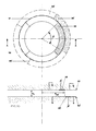
- a cross-section view of a guardring capacitor is given, as it has been built since about hundred years ago after Kelvin's publication and is still being built up till now.
- a bottom electrode C and a top electrode E consisting of two parts, namely a central part G and a concentrically surrounding guardring electrode GR.
- the guarded electrode G sometimes called “island”
- This glassdisc is clamped with-in the guardring GR while using a flexible clampring B, which is pressed downwards in order to generate a firmly pressure on the glassdisc.
- the head of a locking screw A fits in a groove in the edge of the clampingring B, so the unit can be taken apart and replaced with the same force on the glassdisc D.
- a hole has been drilled in the edge of the glass and in the guardring for a small dowel pin P, which will be inserted by a torsion movement after completion of the construction.
- the island electrode G is connected to the connector F.
- the electrode C with the highvoltage connector H is held at a fixed distance from the guardring GR and the island G by three insulated screws J, being surrounded by three spacers T of equal length, made of Pyrex glass tube, of which the ends are flattened and planparallel.
- a cross section of a modified Kelvin guardring capacitor is shown, which has served as a base for the invention, in order to provide several improvements.
- the capacitor has been surrounded by a sleeve or tube K, which can be, depending on the shape of the electrode carriers or supports, of square, rectangular, circular etc. shape, and equipped with terminal 4, permitting the calculation of fringe effects.
- the sleeve K itself causes an inaccuracy in the exact geometry of the fringe.
- the sleeve 4 can be an integral part of the continuous electrode 1, so that however, beside gap s between the island electrode 2 and the guardring electrode 3 there is a second gap s 0 between the guardring electrode 3 and the vertical wall 4.
- the other possible connection is shown.
- the guardring consists of a continuous electrode 10 and a sub-divided electrode 12, which consists of an electrode 13 and two ring-electrodes 14 and 16 separated from each other by gaps 11. Between electrode 10 and electrode 13 respectively 14 is formed a capacitor C o and C 1 resp.; electrode 16 serves as a guardring for the system 13, 14, so that the guardring function of the sleeve(not-shown)could be dispensed with but of course its shielding function should be maintained. While the second ring electrode 16 serves as a guardring, two capacitors Co and C 1 resp.
- first ringelectrode 14 and opposite electrode support 10, from which the ratio can be determined.
- the gauge With minimum value for the ratio C 1 /C 0 the gauge is planparallel. But it is quadratic, which means that there is no sensitivity left at the moment of its reaching the planparallel position.
- a differential plate capacitor is shown as a detection system for setting plate capacitors planparallel.
- This last-mentioned electrode consists of an island 23 and one ring electrode 26, which are separated by a gap 21.
- the ring electrode 26 in its turn is subdivided by radial gaps 25 in four segments 28, 29, each of them spanning an angle of 90°.
- a deviation from planparallelity with a gauge of the type A (fig. 6), if the total electrode configuration is surrounded by a shielding sleeve 27' functioning simultaneously as guardring. If the ring electrode 26 consists of two segments, then only in one direction; if the ring electrode is subdivided in four segments 28, 29 angularly spaced over 90 0 , then in two perpendicular directions.
- the gauge is linear, but is of less accuracy than the type B gauge. Subdivision in four segments in regard to the dividing into two segments has no influence on accuracy, but gives an increase of sensitivity per direction, while the gauge also becomes sensitive for tilting in two perpendicular directions.
- the type B gauge is more accurate.
- the gauge however is quadratic, resulting in a disappearing sensitivity for tilting on the moment that elimination of tilting results in planparallelity, while the direction of tilting cannot be determined, but its magnitude can be measured. Furthermore detection of tilting and its elimination functionates in an analogous manner as in the type A gauge.
- an example is shown of an electrode pattern in an electrode carrier 32, which consists of a combination of patterns mentioned before.
- an island electrode 33 two guardring electrodes 34 and a subdivided ring electrode 36 between the first electrode 33 and two guardring electrodes 34a and 34b.
- the subdivision of the ring electrode 36 consists of segments each spanning an angle of- 90° in such a way that there exist one pair of diametrical segments 38 and another pair of diametrical segments 39, . which are 90 0 offset with respect to each other.
- the sub-electrodes are separated from each other by concentric gaps 31 and radial gaps 35.
- a differential plate capacitor will be formed, being a somewhat more extensive version of the type C.
- differential plate capacitors For setting the gauge planparallel use is made of differential plate capacitors, because these capacitors are not sensitive for lateral displacements, while for lateral adjustment especially use is made of differential cross-capacitors, because these last capacitors have no sensitivity for tilting in the environment of the equilibrium position.
- fig. 8 a number of examples are shown for gap patterns that can be applied on electrode carriers.
- an electrode matrix with rectangular coordinates is shown; in fig. 8B a matrix with oblique coordinates; in fig. 8C with polar coordinates and in fig. 8D with elliptic coordinates.
- a gauge equipped with electrode carriers of the type given in fig. 8A, is ideal for measurements and elimination of sideway displacements, while a gauge with electrode carriers, as given in fig. 8C are especially useful for measurement and elimination of rotations.
- the capacitive gauge can be designed with inside holes 40, as is given in fig. 9, provided that the conditions for shielding and elimination of fringe effects are not affected.
- a rectangular electrode support plate 141 is shown, on which the electrode overlay is divided by a gap-pattern of lines crossing each other perpendicularly, such as horizontal lines 142 a intersected by vertical lines 142 b, into sub-electrode areas in the form of squares 143.
- Two of these squares, to wit areas 143a and 143b cooperate, that means they are simultaneously active, and constitute with the electrode overlay on an opposite electrode support plate (not-shown) two capacitors by means of which a slanted position, if any, can be determined. In the case shown in the figure this is the tilted or slanted position in the Y-direction.
- the formation is possible of two cooperating plate-capacitors, cross-capacitors or a cooperating combination of such plate- and cross-capacitors. All the other squares, such as 143c, function as guard-elements.
- a gap pattern of concentric gaps 145a, b and radial, interrupted gaps 146a, b is provided, whereby the ring electrode 147 is divided into four segments.
- the segments 147a and b are activatable and cooperate in the X -direction for determining the slanted position, if any, in that direction. For the rest they are surrounded by guard-elements 147c.
- an electrode support plate 151 of which the electrode overlay is divided by a pattern of gap lines 152a and 152b resp., which extend as slanting coordinates (X and Y'), into diamond-shaped areas 153.
- Some of them, viz. 153a-d, are activated for the formation of a capacitance with electrode elements on the opposite electrode support plate (not-shown), whereas the remaining areas 153e function as guard-element so that the activatable sub-electrode 153a-d are surrounded from all sides by guard-elements 153e, in a geometrical respect.
- the sub-electrodes 153a and b cooperate (are simultaneously active) for determining the slanting position, if any, in the X-direction, and the sub-electrodes 153 c and d in the slanted Y'-direction. Also in this manner a plan-parallelity of high accuracy (1:10 6 or 1:10 7 ) is obtainable.
- fig. 9Af a situation is shown, comparable to that of fig. 9Ae, for a rotation-symmetrical electrode support plate 154. Also in this case there are three activatable sub-electrodes 157a-c enclosed between concentric and radial gaps 155 and 156, and bound geometrically by elements 157d functioning as guard-element.
- the sub-electrodes 157b constitute both with sub-electrode 157a and with 157c a pair of cooperative sub-electrodes for the determination of the slanted position either in the X-direction or in the Y'-direction.
- sub-electrodes 161a cooperate in the X-direction with adjoining sub-electrode 161b on an electrode support plate 162, being placed with a strongly exaggerated slanted position, opposite an electrode support plate 163.
- the sub-electrode 161a,.b are in geometrical respect separated from each other solely by a gap 164.
- sub-electrode 171a cooperates one moment with adjoining or adjacent sub-electrode 171b and the next moment with opposite sub-electrode 171c.
- the sub-electrodes 173a, 173b cooperate in the X-direction. It is seen that they are not surrounded completely by guard-elements, but meet each other along the interrupted gap 174.
- Fig. 9A The above considerations about Fig. 9A are valid both for plate-capacitors and for cross-capacitors. Both the great accuracy in the plan-parallel setting of planes and the elimination of angular deviations is of special importance in-the manufacture of integrated circuits on chips.
- a gauge using cross capacitances is given.
- a segment 56 in the top electrode carrier 52 functionates together with segment 58' in the bottom electrode carrier 52' as a cross capacitor.
- both the electrode segments are situated on both sides of the common part of the gap 51. All other electrodes, surrounding the concerned segments, are used as guard electrodes.
- the gauge is quadratic with two cross capacitances 56-58' on the left respectively on the right side the gauge becomes linear for small displacements in sideway directions and the component of translation in the X-direction can be measured and eliminated.
- By repeating this process for two cross-capacitances 57-59' one can find the component of translation in the Y-direction.
- the gauge is constructed as a differential cross capacitor, with which sideway deviations (translations) can be measured respectively eliminated.
- the differential cross capacitor of fig. 11, representing type F, is created between a ring electrode 64' in the bottom electrode carrier and the ring segments 68 in the other electrode carrier 62 oriented in pairs, diametrically opposite to each other and ben chosen such that per ring segment with the ring 64 a cross capacitance is .. formed. Centration in the direction concerned has been realised if the two cross capacitances are equal. Repeating this process for the direction perpendicular to the first one with two other ring segments causes the electrode carriers to be centred in a lateral direction. Both centering actions can be repeated several times in order to achieve higher accuracy.
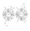
- a gauge with quasi-identic ring patterns has been given.
- a bottom electrode carrier 70' has been given and (on the right) an "identic" top electrode carrier 70.
- Each electrode carrier consists of an island 72', 72, a first ring electrode 73', 73 and a second ring electrode 74', 74.
- the ring electrode 73, 73' is in its turn subdivided in eight segments 71, 76, 77 respectively 71', 76', 77', where the segments 71 and 71' serve as guard electrodes.
- the ring electrode 74 respectively 74' is subdivided in eight segments 78, 79, 80 respectively 78', 79', 80', where the segments 80 and 80' serve as guard electrodes.
- segment 78 of electrode carrier 70 and segment 76' of electrode carrier 70' constitute together a cross capacitance.
- segment 78 of electrode carrier 70 and segment 76' of electrode carrier 70' constitute together a cross capacitance.
- segment 76' of electrode carrier 70' constitute together a cross capacitance.
- a similar second cross capitor can be formed, so that in horizontal direction there exists a differential cross-capacitor. But in the direction perpendicular to the first mentioned direction, one can also distinguish a differential cross-capacitance by combination of 77' and 79.
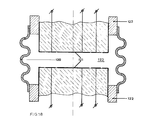
- An important application of the principle of the invention is the measurement of differences in level of a clamped flexible electrode like an electrically conducting membrane (fig. 14), deflecting or sagging under the influence of gravity (gravitational pressure), a pressure difference (mechanical pressure), a difference in electrical potential between electrode carrier and membrane (electrical pressure) and other loads over the divided surface as well as local by acting forces.
- a cross section view of such a gauge system is shown; in fig. 14B a bottom view of the first electrode carrier 81 is shown.
- a flexible electrode carrier 82 is clamped in the wall 83 of a clamping structure 84 and is insulated electrically by insulation material 86.
- the first electrode carrier 81 consists of an island 87, a guardring 88, a ring electrode 89 and a guardring 91, which is connected with the clamping structure 84.
- the dotted line 82' the bending of the flexible electrode 82 under the influence of gravity is given schematically.
- the change of the capacitance ratio is linear up to deviations of several percents of the nominal one to one ratio, unless the distance between electrode carrier 82 and flexible electrode 81 is so large that there cannot longer be spoken of small deflections of the flexible electrode.
- the user is informed about the value of the mass per unit area of the flexible electrode, he is able to calibrate in situ the gauge even in an absolute way, if the local gravity is known, simply by turning over the gauge between the positions in which the flexible electrode either underlies or overlies the other electrode carrier.
- Another important application is the capacitive gauge for measuring thicknesses of coatings, layers, etc. (fig.15). If one realizes that average level differences in the distances between the measuring object 96 and the island electrode 97, respectively the segmented ring electrode 98 with a nominal distance of 100 / cn can be measured with a resolution of seven decimals, one can conclude therefrom that average differences in level can be detected with a resolution of 10 m. Reducing the distance between the electrode carrier 99 and measuring object 96 this resolution can be improved.
- the capacitances are small, namely in the order of 10 pF. Therefore in the bridge circuits for measurements of these capacitances utmost care has to be taken in order to eliminate the influences of parasi- tar capacitances and dielectric losses. For that reason the construction of the capacitive sensor must have such a form, that between the plate electrode 100 (measuring object 96) opposite to the electrode carrier 99 and those electrodes 97, 98 in the electrode carrier, which will not be used as guard electrodes, nowhere in the circuit a path can be found through a dielectricum, differing from that of the space between plate electrode and electrode carrier.
- the existing parasitic capacitances C are partly parallel to the detector 114 and have then only influence on the sensitivity of that detector, but if this sensitivity is of sufficient magnitude, they have no influence on the accuracy of the measurement. Partly they are parallel to the branches of the bridge transformer 112 or they occur between earth and tap of the decade transformer 113. Since both transformers are dimensioned with extreme low impedances, the parallel parasitic capacitances do not affect the voltage ratios in the bridge or do this to an extremely small extent.
- the detector 114 has been chosen as a so-called phase sensitive system, then near bridge balance the output of this lock-in amplifier is directly proportional with the rate of bridge unbalance, if the phase has been set properly.
- the central point of the bridge transformer 112 to which all guard electrodes are connected can be disconnected from earth 115 and via a low impedance DC voltage source connected to earth.
- the input impedance of the detector has to be of the resistive type, to avoid DC voltage loss over the detector.
- the electrode carrier has to be placed within a sleeve, which, where necessary, permits an extremely stable setting of planparallel position and eventually sideway centring of the electrode carrier in regard to the second electrode carrier.
- the sleeve just mentioned, together with the metallized surfaces of the electrode carrier have to form an electrical cage, within which can be made the connections of the several electrodes, not mutually shielded but mutually insulated, with the connectors in the outside wall of the sleeve.
- the leads of the several electrodes have to be shielded electrically from those sub-electrodes which are directly connected to the detector.
- the whole system can be provided with automatic switching of electrode combinations, digital signal processing and controlling and on-line data-processing.
- the electrode pattern has to be provided in the metallic layer, such that the several sub-electrode surfaces become mutually electrically insulated.
- the electrode carrier 102 must have enough rigidity in order to guarantee that the own saggings are negligible with respect to the saggings, if any, of plate electrodes or membrane electrodes 102', which can be disposed as measuring objects opposite to the electrode carrier.
- Size and choice of materials should be such that the influences of thermal expansion of parts of the construction, responsible for the setting of the distance between the electrode carrier and the object to be measured, are eliminated as good as possible. If possible the material of the electrode carrier has to be chosen as insulators with extreme low coefficient of thermal expansion.
- a coefficient of thermal expansion equal 0 of just the electrode carrier material provides a totally temperature - independent measurement of electrode distances.
- the electrode overlays 121 and electrode carriers 122 have to withstand this or, if necessary, the capacitance measuring environment 123 must be provided with a flexible non-permeable envelope 120, as is shown in fig. 18.
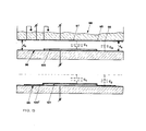
- the capacitieve sensor is used for the measurements of differences in the level of an electrically conducting surface of a measuring object, then at first the capacitance of the plate capacitor is formed by a suitable electrode together with the object (using the ideal plate capacitor formula (3.a), which means the local distance between electrode carrier and object defined by where 0 1 is the surface of the electrode concerned and C 1 the capacitance.
- the value of C 1 will be measured in the capacitance bridge mentioned before in comparison with a standard capacitor C s with known value (fig. 16A).
- C s will be connected between the tap of the decade transformer and the detector entrance, while C 1 will be placed in the other branch of the bridge.
- the electrode carrier 46 is situated underneath flexible electrode 47, which is clamped in a clamping structure 48, electrically insulated from it via insulation material 48a.
- the electrode 47 is flexible in a ringshaped area 47a. Inside that ring the electrode carrier 47 is connected with a mass 49, fitted in the hole 41 in the electrode carrier 46.
Landscapes
- Engineering & Computer Science (AREA)
- Physics & Mathematics (AREA)
- General Physics & Mathematics (AREA)
- Power Engineering (AREA)
- Chemical & Material Sciences (AREA)
- Ceramic Engineering (AREA)
- Microelectronics & Electronic Packaging (AREA)
- Measurement Of Length, Angles, Or The Like Using Electric Or Magnetic Means (AREA)
- Measuring Fluid Pressure (AREA)
- Measuring Instrument Details And Bridges, And Automatic Balancing Devices (AREA)
- Transmission And Conversion Of Sensor Element Output (AREA)
Priority Applications (1)
| Application Number | Priority Date | Filing Date | Title |
|---|---|---|---|
| AT80200660T ATE10553T1 (de) | 1979-07-17 | 1980-07-04 | Kapazitive sonde. |
Applications Claiming Priority (2)
| Application Number | Priority Date | Filing Date | Title |
|---|---|---|---|
| NL7905562A NL7905562A (nl) | 1979-07-17 | 1979-07-17 | Capacitieve meter. |
| NL7905562 | 1979-07-17 |
Publications (2)
| Publication Number | Publication Date |
|---|---|
| EP0023732A1 true EP0023732A1 (de) | 1981-02-11 |
| EP0023732B1 EP0023732B1 (de) | 1984-11-28 |
Family
ID=19833557
Family Applications (1)
| Application Number | Title | Priority Date | Filing Date |
|---|---|---|---|
| EP80200660A Expired EP0023732B1 (de) | 1979-07-17 | 1980-07-04 | Kapazitive Sonde |
Country Status (7)
| Country | Link |
|---|---|
| US (1) | US4347478A (de) |
| EP (1) | EP0023732B1 (de) |
| JP (1) | JPS56107120A (de) |
| AT (1) | ATE10553T1 (de) |
| CA (1) | CA1150527A (de) |
| DE (1) | DE3069697D1 (de) |
| NL (1) | NL7905562A (de) |
Cited By (10)
| Publication number | Priority date | Publication date | Assignee | Title |
|---|---|---|---|---|
| FR2554223A1 (fr) * | 1983-10-28 | 1985-05-03 | Control Data Corp | Jauge de hauteur a capacite et procede et appareil d'etalonnage de cette jauge |
| EP0123646A3 (en) * | 1983-02-23 | 1985-10-09 | Christof W. Burckhardt | Capacitive force measuring device |
| GB2157444A (en) * | 1984-04-10 | 1985-10-23 | Johnson Service Co | Capacitive pressure transducer |
| WO1987004851A1 (en) * | 1986-01-30 | 1987-08-13 | Intellect Electronics Ltd. | Proximity sensing device |
| US4836033A (en) * | 1986-10-13 | 1989-06-06 | Peter Seitz | Capacitive measuring assembly for determining forces and pressures |
| GB2243722A (en) * | 1990-05-03 | 1991-11-06 | Oxley Dev Co Ltd | Improvements in multilayer discoidal capacitors |
| US5237284A (en) * | 1988-09-14 | 1993-08-17 | Presidium Promotions Limited | Measurement of capacitance and parameters related thereto for determining displacement |
| EP0555404A4 (en) * | 1990-10-29 | 1993-09-29 | John S. Borchard | Improved capacitor-sensor |
| EP0821216A3 (de) * | 1996-07-22 | 1999-06-16 | Hewlett-Packard Company | Vorrichtung zur Detektion der Position |
| US20200041311A1 (en) * | 2018-08-06 | 2020-02-06 | Hexagon Technology Center Gmbh | Capacitive distance sensor |
Families Citing this family (25)
| Publication number | Priority date | Publication date | Assignee | Title |
|---|---|---|---|---|
| JPS5759101A (en) * | 1980-09-26 | 1982-04-09 | Hiromi Ogasawara | Noncontacting infinitesimal displacement gauge |
| US4892325A (en) * | 1982-01-08 | 1990-01-09 | Antonio Nicholas F D | Motion detector |
| US5114171A (en) * | 1982-01-08 | 1992-05-19 | Antonio Nicholas F D | Motion detector |
| US4538069A (en) * | 1983-10-28 | 1985-08-27 | Control Data Corporation | Capacitance height gage applied in reticle position detection system for electron beam lithography apparatus |
| CA1191261A (fr) * | 1983-12-14 | 1985-07-30 | Francois Lalonde | Appareil de mesure dynamique et sans contact de faibles distances |
| US4755731A (en) * | 1987-01-15 | 1988-07-05 | Mcdonnell Douglas Corporation | Optical scanning transducer |
| US5012197A (en) * | 1988-04-19 | 1991-04-30 | Volkhard Seiffert | Apparatus and method for determining the relative percentages of components in a mixture |
| US5036286A (en) * | 1988-06-03 | 1991-07-30 | The Research Corporation Of The University Of Hawaii | Magnetic and electric force sensing method and apparatus |
| GB9021448D0 (en) * | 1990-10-03 | 1990-11-14 | Renishaw Plc | Capacitance sensing probe |
| US5581035A (en) * | 1994-08-29 | 1996-12-03 | The Charles Stark Draper Laboratory, Inc. | Micromechanical sensor with a guard band electrode |
| US5646348A (en) * | 1994-08-29 | 1997-07-08 | The Charles Stark Draper Laboratory, Inc. | Micromechanical sensor with a guard band electrode and fabrication technique therefor |
| US5753820A (en) * | 1996-10-25 | 1998-05-19 | Arthur D. Little, Inc. | Fluid pressure sensing unit incorporating diaphragm deflection sensing array |
| US6480007B1 (en) * | 2000-04-05 | 2002-11-12 | Trw Inc. | Capacitive sensor excitation techniques |
| US6925398B2 (en) * | 2003-07-07 | 2005-08-02 | Colorado Vnet, Llc | Water measurement apparatus and methods |
| US9360968B2 (en) * | 2007-02-22 | 2016-06-07 | Cypress Semiconductor Corporation | Cursor control device and method of operation |
| US20090198458A1 (en) * | 2008-01-29 | 2009-08-06 | Mcdermid John | Water measurement auto-networks |
| US8359932B2 (en) * | 2010-07-19 | 2013-01-29 | Goodrich Corporation | Systems and methods for mounting landing gear strain sensors |
| DE102011015589B3 (de) * | 2011-03-30 | 2012-04-12 | Techem Energy Services Gmbh | Anordnung und Verfahren zur kapazitiven Abtastung der Drehbwegung eines Drehelements |
| WO2012144903A2 (en) * | 2011-04-22 | 2012-10-26 | Mapper Lithography Ip B.V. | Lithography system for processing a target, such as a wafer, a method for operating a lithography system for processing a target, such as a wafer and a substrate for use in such a lithography system |
| US9180288B2 (en) | 2011-09-01 | 2015-11-10 | Zoll Medical Corporation | Medical equipment electrodes |
| ES2690860T3 (es) * | 2012-11-05 | 2018-11-22 | CSEM Centre Suisse d'Electronique et de Microtechnique SA - Recherche et Développement | Método para medición de la impedancia biológica |
| US9229592B2 (en) | 2013-03-14 | 2016-01-05 | Synaptics Incorporated | Shear force detection using capacitive sensors |
| CN103197181B (zh) * | 2013-03-27 | 2015-12-23 | 中国计量科学研究院 | 一种屏蔽电极模型组件及其应用 |
| CN103207288B (zh) * | 2013-03-27 | 2015-06-24 | 中国计量科学研究院 | 一种实心电补偿辅助电极及其应用 |
| DE112016001348T5 (de) * | 2015-03-23 | 2018-02-15 | Iee International Electronics & Engineering S.A. | Kapazitives Erfassungssystem mit Gerätediagnosekonzept zur Erfassung einer Sensorunterbrechung |
Citations (5)
| Publication number | Priority date | Publication date | Assignee | Title |
|---|---|---|---|---|
| DE563428C (de) * | 1928-11-08 | 1932-11-04 | Telefunken Gmbh | Verfahren zum Untersuchen von akustischen Flaechenstrahlern, insbesondere Geigen u. dgl. |
| FR1599174A (de) * | 1967-12-06 | 1970-07-15 | ||
| GB1321831A (en) * | 1969-06-20 | 1973-07-04 | Nat Res Dev | Positional transducers |
| DE2306752B1 (de) * | 1972-09-07 | 1974-03-28 | Maag-Zahnräder & - Maschinen AG, Zürich (Schweiz) | Vorrichtung zur kapazitiven abtastung von kreis- und laengenteilungen |
| US4092579A (en) * | 1976-12-15 | 1978-05-30 | Contraves Goerz Corporation | Brushless printed circuit resolver |
Family Cites Families (8)
| Publication number | Priority date | Publication date | Assignee | Title |
|---|---|---|---|---|
| US3084558A (en) * | 1958-11-28 | 1963-04-09 | North American Aviation Inc | Capacitance pickoff with low coercion |
| US3119266A (en) * | 1960-11-10 | 1964-01-28 | Duane E Atkinson | Level indicating system, method and probe |
| US3515987A (en) * | 1967-10-20 | 1970-06-02 | Avco Corp | Coplanar dielectric probe having means for minimizing capacitance from stray sources |
| US3805150A (en) * | 1970-08-17 | 1974-04-16 | Ade Corp | Environment immune high precision capacitive gauging system |
| US3739265A (en) * | 1970-09-09 | 1973-06-12 | J Skildum | Test instrument and method for isolating and measuring the capacitance due to a particular functional group in a liquid |
| JPS5149421B2 (de) * | 1972-07-24 | 1976-12-27 | ||
| US3812424A (en) * | 1972-09-27 | 1974-05-21 | Ade Corp | Capacitive wire gauge |
| DE2448205C2 (de) * | 1974-10-09 | 1985-08-22 | Endress U. Hauser Gmbh U. Co, 7867 Maulburg | Kapazitive Sonde |
-
1979
- 1979-07-17 NL NL7905562A patent/NL7905562A/nl not_active Application Discontinuation
-
1980
- 1980-07-04 DE DE8080200660T patent/DE3069697D1/de not_active Expired
- 1980-07-04 EP EP80200660A patent/EP0023732B1/de not_active Expired
- 1980-07-04 AT AT80200660T patent/ATE10553T1/de not_active IP Right Cessation
- 1980-07-07 US US06/166,627 patent/US4347478A/en not_active Expired - Lifetime
- 1980-07-17 JP JP9814780A patent/JPS56107120A/ja active Pending
- 1980-07-17 CA CA000356399A patent/CA1150527A/en not_active Expired
Patent Citations (5)
| Publication number | Priority date | Publication date | Assignee | Title |
|---|---|---|---|---|
| DE563428C (de) * | 1928-11-08 | 1932-11-04 | Telefunken Gmbh | Verfahren zum Untersuchen von akustischen Flaechenstrahlern, insbesondere Geigen u. dgl. |
| FR1599174A (de) * | 1967-12-06 | 1970-07-15 | ||
| GB1321831A (en) * | 1969-06-20 | 1973-07-04 | Nat Res Dev | Positional transducers |
| DE2306752B1 (de) * | 1972-09-07 | 1974-03-28 | Maag-Zahnräder & - Maschinen AG, Zürich (Schweiz) | Vorrichtung zur kapazitiven abtastung von kreis- und laengenteilungen |
| US4092579A (en) * | 1976-12-15 | 1978-05-30 | Contraves Goerz Corporation | Brushless printed circuit resolver |
Non-Patent Citations (1)
| Title |
|---|
| JOURNAL OF PHYSICS E SCIENTIFIC INSTRUMENTS, Vol. 9, No. 8, August 1976, pages 639-646 London, G.B. J.C.S. RICHARDS: "Linear capacitance proximity gauges with high resolution" * Abstract; paragraph 4; figure 2 * * |
Cited By (11)
| Publication number | Priority date | Publication date | Assignee | Title |
|---|---|---|---|---|
| EP0123646A3 (en) * | 1983-02-23 | 1985-10-09 | Christof W. Burckhardt | Capacitive force measuring device |
| FR2554223A1 (fr) * | 1983-10-28 | 1985-05-03 | Control Data Corp | Jauge de hauteur a capacite et procede et appareil d'etalonnage de cette jauge |
| GB2157444A (en) * | 1984-04-10 | 1985-10-23 | Johnson Service Co | Capacitive pressure transducer |
| WO1987004851A1 (en) * | 1986-01-30 | 1987-08-13 | Intellect Electronics Ltd. | Proximity sensing device |
| US4836033A (en) * | 1986-10-13 | 1989-06-06 | Peter Seitz | Capacitive measuring assembly for determining forces and pressures |
| US5237284A (en) * | 1988-09-14 | 1993-08-17 | Presidium Promotions Limited | Measurement of capacitance and parameters related thereto for determining displacement |
| GB2243722A (en) * | 1990-05-03 | 1991-11-06 | Oxley Dev Co Ltd | Improvements in multilayer discoidal capacitors |
| EP0555404A4 (en) * | 1990-10-29 | 1993-09-29 | John S. Borchard | Improved capacitor-sensor |
| EP0821216A3 (de) * | 1996-07-22 | 1999-06-16 | Hewlett-Packard Company | Vorrichtung zur Detektion der Position |
| US20200041311A1 (en) * | 2018-08-06 | 2020-02-06 | Hexagon Technology Center Gmbh | Capacitive distance sensor |
| US12085386B2 (en) * | 2018-08-06 | 2024-09-10 | Hexagon Technology Center Gmbh | Capacitive distance sensor |
Also Published As
| Publication number | Publication date |
|---|---|
| CA1150527A (en) | 1983-07-26 |
| ATE10553T1 (de) | 1984-12-15 |
| US4347478A (en) | 1982-08-31 |
| DE3069697D1 (en) | 1985-01-10 |
| NL7905562A (nl) | 1981-01-20 |
| JPS56107120A (en) | 1981-08-25 |
| EP0023732B1 (de) | 1984-11-28 |
Similar Documents
| Publication | Publication Date | Title |
|---|---|---|
| US4347478A (en) | Capacitive gauge | |
| EP0344942B1 (de) | Kapazitive Inkrementalwegmessung und Kontrolle | |
| Heerens | Application of capacitance techniques in sensor design | |
| JP3579739B2 (ja) | 可変容量性トランスジューサ | |
| US4542436A (en) | Linearized capacitive pressure transducer | |
| US3805150A (en) | Environment immune high precision capacitive gauging system | |
| US4572006A (en) | Load cells | |
| US3732553A (en) | Capacitive pick-off transducer | |
| JPH05215506A (ja) | 容量性位置センサ | |
| US3706919A (en) | Capacitive gauge | |
| EP1320723B1 (de) | Winkelwandler | |
| US8847611B2 (en) | Capacitive differential quadrature rotary position sensor | |
| JPH0136563B2 (de) | ||
| JP3556949B2 (ja) | ポテンショメータ | |
| US3249854A (en) | Displacement measuring device | |
| JPWO1994011888A1 (ja) | ポテンショメータ | |
| US3090934A (en) | Reduction of unwanted coupling between transformer members of position-measuring transformers | |
| US4082990A (en) | Electrostatic pickoff and torquer | |
| Wolffenbuttel et al. | An integrable capacitive angular displacement sensor with improved linearity | |
| Field et al. | Capacitive position sensor with simultaneous, linear X–Y readout | |
| WO2000005593A1 (en) | Variable dielectric position transducer and method | |
| SU1249309A1 (ru) | Емкостный измеритель угловых перемещений | |
| JPH06341805A (ja) | 静電容量式リニアスケール | |
| SU1250836A1 (ru) | Емкостной преобразователь линейных перемещений | |
| SU1249319A1 (ru) | Емкостной преобразователь угловых перемещений с переменным зазором |
Legal Events
| Date | Code | Title | Description |
|---|---|---|---|
| PUAI | Public reference made under article 153(3) epc to a published international application that has entered the european phase |
Free format text: ORIGINAL CODE: 0009012 |
|
| AK | Designated contracting states |
Designated state(s): AT BE CH DE FR GB IT LU NL SE |
|
| 17P | Request for examination filed |
Effective date: 19810810 |
|
| ITF | It: translation for a ep patent filed | ||
| GRAA | (expected) grant |
Free format text: ORIGINAL CODE: 0009210 |
|
| AK | Designated contracting states |
Designated state(s): AT BE CH DE FR GB IT LI LU NL SE |
|
| REF | Corresponds to: |
Ref document number: 10553 Country of ref document: AT Date of ref document: 19841215 Kind code of ref document: T |
|
| REF | Corresponds to: |
Ref document number: 3069697 Country of ref document: DE Date of ref document: 19850110 |
|
| ET | Fr: translation filed | ||
| PLBE | No opposition filed within time limit |
Free format text: ORIGINAL CODE: 0009261 |
|
| STAA | Information on the status of an ep patent application or granted ep patent |
Free format text: STATUS: NO OPPOSITION FILED WITHIN TIME LIMIT |
|
| 26N | No opposition filed | ||
| ITTA | It: last paid annual fee | ||
| PGFP | Annual fee paid to national office [announced via postgrant information from national office to epo] |
Ref country code: FR Payment date: 19920630 Year of fee payment: 13 |
|
| PGFP | Annual fee paid to national office [announced via postgrant information from national office to epo] |
Ref country code: SE Payment date: 19920702 Year of fee payment: 13 |
|
| PGFP | Annual fee paid to national office [announced via postgrant information from national office to epo] |
Ref country code: GB Payment date: 19920706 Year of fee payment: 13 |
|
| PGFP | Annual fee paid to national office [announced via postgrant information from national office to epo] |
Ref country code: LU Payment date: 19920716 Year of fee payment: 13 Ref country code: AT Payment date: 19920716 Year of fee payment: 13 |
|
| PGFP | Annual fee paid to national office [announced via postgrant information from national office to epo] |
Ref country code: NL Payment date: 19920731 Year of fee payment: 13 |
|
| PGFP | Annual fee paid to national office [announced via postgrant information from national office to epo] |
Ref country code: BE Payment date: 19920807 Year of fee payment: 13 |
|
| PGFP | Annual fee paid to national office [announced via postgrant information from national office to epo] |
Ref country code: DE Payment date: 19920826 Year of fee payment: 13 |
|
| PGFP | Annual fee paid to national office [announced via postgrant information from national office to epo] |
Ref country code: CH Payment date: 19921023 Year of fee payment: 13 |
|
| EPTA | Lu: last paid annual fee | ||
| PG25 | Lapsed in a contracting state [announced via postgrant information from national office to epo] |
Ref country code: LU Free format text: LAPSE BECAUSE OF NON-PAYMENT OF DUE FEES Effective date: 19930704 Ref country code: GB Effective date: 19930704 Ref country code: AT Effective date: 19930704 |
|
| PG25 | Lapsed in a contracting state [announced via postgrant information from national office to epo] |
Ref country code: SE Effective date: 19930705 |
|
| PG25 | Lapsed in a contracting state [announced via postgrant information from national office to epo] |
Ref country code: LI Effective date: 19930731 Ref country code: CH Effective date: 19930731 Ref country code: BE Effective date: 19930731 |
|
| BERE | Be: lapsed |
Owner name: PEERBOLTE GERRIT HENDRIK Effective date: 19930731 Owner name: HEERENS WILLEM CHRISTIAAN Effective date: 19930731 |
|
| PG25 | Lapsed in a contracting state [announced via postgrant information from national office to epo] |
Ref country code: NL Effective date: 19940201 |
|
| GBPC | Gb: european patent ceased through non-payment of renewal fee |
Effective date: 19930704 |
|
| NLV4 | Nl: lapsed or anulled due to non-payment of the annual fee | ||
| PG25 | Lapsed in a contracting state [announced via postgrant information from national office to epo] |
Ref country code: FR Effective date: 19940331 |
|
| REG | Reference to a national code |
Ref country code: CH Ref legal event code: PL |
|
| PG25 | Lapsed in a contracting state [announced via postgrant information from national office to epo] |
Ref country code: DE Effective date: 19940401 |
|
| REG | Reference to a national code |
Ref country code: FR Ref legal event code: ST |
|
| EUG | Se: european patent has lapsed |
Ref document number: 80200660.1 Effective date: 19940210 |