EP0023819A1 - Mécanisme de levage pour plate-forme de chargement de véhicule ou autre plate-forme de chargement - Google Patents
Mécanisme de levage pour plate-forme de chargement de véhicule ou autre plate-forme de chargement Download PDFInfo
- Publication number
- EP0023819A1 EP0023819A1 EP80302608A EP80302608A EP0023819A1 EP 0023819 A1 EP0023819 A1 EP 0023819A1 EP 80302608 A EP80302608 A EP 80302608A EP 80302608 A EP80302608 A EP 80302608A EP 0023819 A1 EP0023819 A1 EP 0023819A1
- Authority
- EP
- European Patent Office
- Prior art keywords
- platform
- pivots
- board
- tail
- lever
- Prior art date
- Legal status (The legal status is an assumption and is not a legal conclusion. Google has not performed a legal analysis and makes no representation as to the accuracy of the status listed.)
- Granted
Links
- 238000005096 rolling process Methods 0.000 abstract description 2
- 238000010276 construction Methods 0.000 description 1
- 230000008602 contraction Effects 0.000 description 1
- 238000006073 displacement reaction Methods 0.000 description 1
- 239000012530 fluid Substances 0.000 description 1
- 210000003371 toe Anatomy 0.000 description 1
Images

Classifications
-
- B—PERFORMING OPERATIONS; TRANSPORTING
- B60—VEHICLES IN GENERAL
- B60P—VEHICLES ADAPTED FOR LOAD TRANSPORTATION OR TO TRANSPORT, TO CARRY, OR TO COMPRISE SPECIAL LOADS OR OBJECTS
- B60P1/00—Vehicles predominantly for transporting loads and modified to facilitate loading, consolidating the load, or unloading
- B60P1/44—Vehicles predominantly for transporting loads and modified to facilitate loading, consolidating the load, or unloading having a loading platform thereon raising the load to the level of the load-transporting element
- B60P1/4457—Means for immobilising the load or preventing it from rolling off during lifting; Man-rails
-
- B—PERFORMING OPERATIONS; TRANSPORTING
- B60—VEHICLES IN GENERAL
- B60P—VEHICLES ADAPTED FOR LOAD TRANSPORTATION OR TO TRANSPORT, TO CARRY, OR TO COMPRISE SPECIAL LOADS OR OBJECTS
- B60P1/00—Vehicles predominantly for transporting loads and modified to facilitate loading, consolidating the load, or unloading
- B60P1/44—Vehicles predominantly for transporting loads and modified to facilitate loading, consolidating the load, or unloading having a loading platform thereon raising the load to the level of the load-transporting element
- B60P1/4414—Vehicles predominantly for transporting loads and modified to facilitate loading, consolidating the load, or unloading having a loading platform thereon raising the load to the level of the load-transporting element and keeping the loading platform parallel to the ground when raising the load
-
- Y—GENERAL TAGGING OF NEW TECHNOLOGICAL DEVELOPMENTS; GENERAL TAGGING OF CROSS-SECTIONAL TECHNOLOGIES SPANNING OVER SEVERAL SECTIONS OF THE IPC; TECHNICAL SUBJECTS COVERED BY FORMER USPC CROSS-REFERENCE ART COLLECTIONS [XRACs] AND DIGESTS
- Y10—TECHNICAL SUBJECTS COVERED BY FORMER USPC
- Y10S—TECHNICAL SUBJECTS COVERED BY FORMER USPC CROSS-REFERENCE ART COLLECTIONS [XRACs] AND DIGESTS
- Y10S414/00—Material or article handling
- Y10S414/13—Handlers utilizing parallel links
Definitions
- This invention relates to a swivelling lift mechanism for raising and lowering a load platform and has a particularly useful but not exclusive application in a mechanism for moving a vehicle tail-board from its initial vertical postion at the rear of the vehicle body into a horizontal position and then in substantially the same horizontal attitude to ground level and back again. whereby the tail-board can be used to carry loads between the floor of the vehicle and a lower level.
- a lift mechanism for a load-carrying platform comprising at least one parallelogram linkage constituted by two main levers each having three non-colinear pivots and the pivots on the two levers defining substantially identical triangles, and the levers being horizontally offset from each other in a direction towards and away from the platform, one pair cf corresponding pivots on the two levers being respectively conncted to the platform at two fixed points which are spced apart a predetermined distance in the direction of the length of the platform, the pivots constituting the second pair being spaced spart by said predetermined distance and interconnected by a synchronising link, and the pivots constituting the third pair being spaced apart by said predetormined distatce and inter connected by a tilting lever, cne of the pivots of the third pair having a fixed mounging on the vehicle, means for rotating the main levers about their respective pivots constituting the third pair, and means for selectively moving the tilting lever about the fixed pivot point into
- At least the main lever nearest the platform is cranked and/or cut away in the region of said first pivot thereof in such a manner that the parts of the; lever which overlap the platform do not protrude above the load-carrying surface of the platform in any position of the platform within its range of movement.
- the pivot having the fixed mounting is the pivot of the third pair furthest from the platform when the latter is in a horizontal attitude.
- a stop operative to support the tilting lever in a first position in which the pivot constituting the third pair are horizontally aligned with each other.
- the first said stop is removable and a second stop is provided which operates, on removal of the first stop, to permit the platform to rotate the tilt lever about said fixed pivot beyond the first said position towards a second position which is determined by the second stop, and in which the platform is inclined downwardly from its edge nearer said fixed mounting.
- the main levers are connected to the platform adjacent the widthwise edge of the platform, and the platform has pivotally connected to its opposite widthwise edge a ramp member, and a rod is connected between the ramp member and the linkage in such a manner that movement of the linkage to raise the platform moves the rod in a sense to swivel the ramp upward about its pivot connection to the platform.
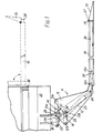
- the tail-board 10 is supported by two identical parallelogram linkages 11 which are spaced apart widthwise of the tail-board (i.e. transversely of the vehicle). These linkages are disposed underneath the floor of the vehicle body, and are connected to the tail-board at locations well inboard of the sides of the tail-board.
- Each of the linkages includes two main levers 12, 13 each of which provides three non-colinear pivots, and the triangles defined by these pivots are identical.
- the levers are however of somewhat complex shape for reasons whihc will become clear presently.
- Levers 12, 13 are spaced apa.rt in a direction lengthwise of the vehicle and are slightly offset laterally from one another to enable them to swing in respective vertical planes.
- the pivots of the two levers form three pairs 12a and 13a, 12b and 13b, and 12c and 13c respectively and the two pivots of each pair are linked together.
- Pivots 12a and 13a are linked by one arm of a tilt lever 14, pivots 12b and 13b are linked by a synchronising link 16, and pivots 12c and 13c are linked together by being connected to the tail-board at positions spaced apart lengthwise of the tail-board.
- the pivot 12a is mounted on a bracket 18 fixed to the chassis 20 of the vehicle and thus provides the only fixed support of the linkage.
- the tilting lever 14 has a crank arm 21, and a hydraulic jack 22 is connected between the crank arm and a lug on the bracket 18.
- a second hydraulic jack 23 is pivotally connected at 25 to a further lug 24 on the bracket 18 and to a pin 26 on the main lever 12, the position of the pin being selected so that it does not come into line with point 25 and pivot 12a in the range of movement of the linkage.
- the drawing shows the tail-bpard in its lowermost position.
- the tilt lever 14 is prevented from rotating in a clockwise direction by a displaceable stop 28 disposed between the arm 21 and second, fixed, stop 29 carried by the bracket 18.
- Extension of the jack 23 causes the tail-board to be raised in a horizontal attitude to the position shown in broken lines substantially level with the floor of the vehicle body.
- jack 22 is extended and causes the tilting lever 14 to swivel through 90° about the pivot 12a, which in turn causes lever 13 to move bodily in an arcuate path, about the pivots 12a, 12b and 12c, moving pivot 13c into a position vertically above pivot 12c and hence moving the tail-board into its vertical position.
- Contraction of the jacks in the reverse sequence returns the tail-board first into a horizontal attitude and then in the same attitude to ground level.
- attitude of the tail-board corresponds to that of the arm 14 at all times.
- Displacement of the displaceable stop 28 allows the arm 21 to swivel in a clockwise direction until it engages the fixed stop 29, causing the platform to tilt, say 10 0 into a downwardly inclined position, and permit-] ting the rearward end of the tail-board to rest on a loading dock or other surface.
- the part of lever 13 which extends along the tail-board does not project above the surface of the tail-board anywhere along its length, and the arrangement therefore permits a load to be moved on to the tail-board from either side as well as from the end.
- the resulting elbow portion of the lever 13 can be arranged not to hit the ground during the final stages of lowering the tail-board.
- the design of the said part of lever 13 may be such that a tolerance of 20° of rotation of the lever 13 can be obtained in this respect at the lower end of the movement of the tail-board, which can be utilised to compensate for differences in the floor height between one vehicle and another and for the deflection of the springs of a vehicle which occurs with variation of the load on the vehicle.
- the levers 12 and 13 are cut away locally so that they clear the rearmost transverse bearer 30 of the floor of the vehicle body as the tail-board is raised to that level.
- the tail-board has a ramp 35 hinged to it at its rear edge, the hinge 36 being disposed at the top edges of these components as shown so that the ramp can pivot upward if it strikes an obstruction such as the toes of one of the attendant personnel.
- the weight of the ramp maintains it in contact with a push-rod 38 which is slidably mounted in a guide recess in one end edge of the tail-board and which is resiliently urged forward by a spring (not shown).
- the push-rod engages a cam surface formed by a lobe 39 on the outer periphery of the boss on the main lever 13 which boss encircles the pivot 13
- the ramp lifting device may, if desired, be rendered inoperative, for example by permitting the ramp to be pushed lengthwise of its hinge connection to disengage the ramp from the push-rod, and a spring 37 may be provided which returns the ramp to its former position when the platform is next lowered to the ground.
- the ramp therefore performs three useful functions. Firstly it operates as a ramp during loading and unloading; secondly, being in a raised attitude during lifting and lowering of the tail-board, it prevents the load from rolling or sliding off the tail-board; and thirdly, when the tail-board is in a vertical position, the ramp increases the effective height of the tail-board.
- the ramp operating mechanism can take many alternative forms.
- the ramp may for example be raised by a hydraulic jack operated by low pressure fluid. Such jack could be connected in circuit with the main lifting jack 23 so as to raise the ramp before lifting commences.
- the front end of the push-rod may be linked to a crank arm in the place of lobe 39.
- the ramp may be operated by the main hydraulic jack 23 through a lost-motion device, permitting one end of the jack, say pivot 2Xto move relative to its carrying member (lug. 24) during the first part of the jack movement, and employing this movement to operate the ramp. This arrangement too ensures that the ramp is raised before lifting commences.
- the illustrated lift mechanism as applied to a tail-board provides a tail which is relatively thin, facilitating movement of a load onto and off the tail-board, and furthermore enables all the required movements of the tail-board to be motor-driven. Additionally the lift mechanism enables these movements to be carried out without any necessity for altering the part of the standard supporting structure for the floor of the vehicle adjacent the tail-board.
- the underneath (rearward) face of the tail-board is preferably recessed at its side edges so that a safety gap is left between the tail-board and the ground at these edges when the tail-board is fully lowered.
- the thickness of the tail-board over the remainder of its area may if desired be such as to enclose the structural members to which the main levers 12 and 13 are connected at 12c and 13c.
- the "skin" member 41 which defines part of the recess may be of corrugated or grooved form as shown and may be curved upward at its outer side edges wherein it joins the load- bearing surface 42 of the tail-board.
Landscapes
- Engineering & Computer Science (AREA)
- Transportation (AREA)
- Mechanical Engineering (AREA)
- Auxiliary Methods And Devices For Loading And Unloading (AREA)
- Vehicle Step Arrangements And Article Storage (AREA)
Priority Applications (1)
| Application Number | Priority Date | Filing Date | Title |
|---|---|---|---|
| DE8282110484T DE3071969D1 (en) | 1979-08-03 | 1980-07-30 | Load-carrying lift mechanism for a vehicle |
Applications Claiming Priority (2)
| Application Number | Priority Date | Filing Date | Title |
|---|---|---|---|
| GB7927159 | 1979-08-03 | ||
| GB7927159 | 1979-08-03 |
Related Child Applications (1)
| Application Number | Title | Priority Date | Filing Date |
|---|---|---|---|
| EP82110484.1 Division-Into | 1982-11-13 |
Publications (2)
| Publication Number | Publication Date |
|---|---|
| EP0023819A1 true EP0023819A1 (fr) | 1981-02-11 |
| EP0023819B1 EP0023819B1 (fr) | 1984-09-12 |
Family
ID=10506983
Family Applications (2)
| Application Number | Title | Priority Date | Filing Date |
|---|---|---|---|
| EP80302608A Expired EP0023819B1 (fr) | 1979-08-03 | 1980-07-30 | Mécanisme de levage pour plate-forme de chargement de véhicule ou autre plate-forme de chargement |
| EP82110484A Expired EP0078065B1 (fr) | 1979-08-03 | 1980-07-30 | Mécanisme élévateur pour dispositif de chargement d'un véhicule |
Family Applications After (1)
| Application Number | Title | Priority Date | Filing Date |
|---|---|---|---|
| EP82110484A Expired EP0078065B1 (fr) | 1979-08-03 | 1980-07-30 | Mécanisme élévateur pour dispositif de chargement d'un véhicule |
Country Status (6)
| Country | Link |
|---|---|
| US (1) | US4344508A (fr) |
| EP (2) | EP0023819B1 (fr) |
| JP (1) | JPS5639935A (fr) |
| AU (1) | AU534251B2 (fr) |
| DE (1) | DE3069156D1 (fr) |
| GB (1) | GB2055746B (fr) |
Cited By (2)
| Publication number | Priority date | Publication date | Assignee | Title |
|---|---|---|---|---|
| EP0078065A2 (fr) | 1979-08-03 | 1983-05-04 | Ray Smith (Tail Lifts) Limited | Mécanisme élévateur pour dispositif de chargement d'un véhicule |
| CN108042273A (zh) * | 2017-12-21 | 2018-05-18 | 重庆馨康阁科技有限公司 | 救护车担架梯板 |
Families Citing this family (19)
| Publication number | Priority date | Publication date | Assignee | Title |
|---|---|---|---|---|
| JPS58186851U (ja) * | 1982-06-09 | 1983-12-12 | 東芝テック株式会社 | ミ−トグラインダ |
| GB8311632D0 (en) * | 1983-04-28 | 1983-06-02 | Fretwell Ltd P & J | Vehicle lift devices |
| US4606433A (en) * | 1984-10-29 | 1986-08-19 | Reb Manufacturing, Inc. | Step convertible platform lift |
| ZA859080B (en) * | 1984-11-29 | 1986-08-27 | Hynbrood Pty Ltd | Trolley carrier |
| BE1001880A4 (nl) * | 1987-06-29 | 1990-04-03 | Hollander Omer D | Laadbrug voor transportwagens. |
| JP2725006B2 (ja) * | 1987-08-18 | 1998-03-09 | 和光工業株式会社 | 車輛用昇降装置 |
| FR2637580B1 (fr) * | 1988-10-07 | 1990-12-14 | Erhel | Perfectionnements aux plates-formes pour hayons elevateurs |
| DE68925368T2 (de) * | 1988-11-05 | 1996-08-14 | Ricon Uk Ltd | Fahrzeuge und ladebordwände |
| US5224723A (en) * | 1992-05-26 | 1993-07-06 | Hatas Peter J | Vehicle step and platform apparatus |
| US5449267A (en) * | 1994-05-16 | 1995-09-12 | Maxon Industries, Inc. | Liftgate platform with latchable retention ramp |
| US6364597B2 (en) * | 1997-05-23 | 2002-04-02 | E & P Lifts Corporation | Hydraulic lift for motor home |
| US6086312A (en) * | 1999-03-17 | 2000-07-11 | Ziaylek; Michael P. | Tank handling apparatus |
| US6682114B1 (en) | 2003-02-26 | 2004-01-27 | Unigroup, Inc. | Method and apparatus for extending a length of a lift gate |
| US7137479B2 (en) * | 2004-10-08 | 2006-11-21 | Michael P. Ziaylek | Powered ladder storage apparatus for an emergency vehicle |
| US7354090B1 (en) * | 2005-05-23 | 2008-04-08 | David Allen Pomorski | Self-supporting tailgate table/extension |
| US20110057008A1 (en) * | 2009-09-10 | 2011-03-10 | Softride, Inc. | Spring assist system for vehicle-mounted racks |
| US9862430B1 (en) * | 2016-08-26 | 2018-01-09 | Ford Global Technologies, Llc | Tailgate cover |
| US11623578B2 (en) | 2018-04-24 | 2023-04-11 | Michael P. Ziaylek | Systems for storing and retrieving ladders and other objects |
| US10689906B2 (en) | 2018-04-24 | 2020-06-23 | Michael P. Ziaylek | Systems for storing and retrieving ladders and other objects |
Citations (4)
| Publication number | Priority date | Publication date | Assignee | Title |
|---|---|---|---|---|
| US2525424A (en) * | 1947-06-20 | 1950-10-10 | Anthony Co | Balancing means for tail gate elevators |
| DE7235115U (de) * | 1972-09-23 | 1974-03-07 | Dautel E Kipperbau | Ladevorrichtung für Lastfahrzeugaufbauten |
| DE2253805A1 (de) * | 1972-11-03 | 1974-05-16 | Dautel Emil Kipperbau | Ladevorrichtung fuer lastfahrzeugaufbauten |
| BE859070A (nl) * | 1977-09-27 | 1978-03-28 | Hollander Omer A E D | Inrichting voor het wegschuifbaar bevestigen van een laadbrug onder een transportwagen |
Family Cites Families (9)
| Publication number | Priority date | Publication date | Assignee | Title |
|---|---|---|---|---|
| FR1143534A (fr) * | 1953-11-21 | 1957-10-02 | Dumont & Freres G | Perfectionnements apportés à la manutention et au transport des containers |
| DE1060424B (de) * | 1955-07-20 | 1959-07-02 | Otto Kessler | Fahrzeug fuer den Transport von Kaltbindemitteln in Faessern |
| FR2067986A5 (fr) * | 1969-11-24 | 1971-08-20 | Dusser Alain | |
| DE2051585A1 (de) * | 1970-10-21 | 1972-05-04 | Robert Bosch Gmbh, 7000 Stuttgart | Seitenhublader |
| US4005788A (en) * | 1975-10-01 | 1977-02-01 | Pepsi Co. Inc. | Vehicular delivery ramp apparatus |
| US4078676A (en) * | 1976-11-10 | 1978-03-14 | Magline, Inc. | Self storing lift gate assembly |
| GB1552578A (en) * | 1978-03-29 | 1979-09-12 | Ratcliff Tail Lifts Ltd | Ramps |
| US4344508A (en) | 1979-08-03 | 1982-08-17 | Alcan Research And Development Limited | Lift mechanism for a vehicle tail-board or other load platform |
| GB2067503A (en) * | 1980-01-15 | 1981-07-30 | Ratcliff Tail Lifts Ltd | Platform and stop bar assembly |
-
1980
- 1980-07-29 US US06/173,337 patent/US4344508A/en not_active Expired - Lifetime
- 1980-07-30 GB GB8024987A patent/GB2055746B/en not_active Expired
- 1980-07-30 DE DE8080302608T patent/DE3069156D1/de not_active Expired
- 1980-07-30 EP EP80302608A patent/EP0023819B1/fr not_active Expired
- 1980-07-30 EP EP82110484A patent/EP0078065B1/fr not_active Expired
- 1980-08-01 AU AU61002/80A patent/AU534251B2/en not_active Ceased
- 1980-08-04 JP JP10705580A patent/JPS5639935A/ja active Pending
Patent Citations (4)
| Publication number | Priority date | Publication date | Assignee | Title |
|---|---|---|---|---|
| US2525424A (en) * | 1947-06-20 | 1950-10-10 | Anthony Co | Balancing means for tail gate elevators |
| DE7235115U (de) * | 1972-09-23 | 1974-03-07 | Dautel E Kipperbau | Ladevorrichtung für Lastfahrzeugaufbauten |
| DE2253805A1 (de) * | 1972-11-03 | 1974-05-16 | Dautel Emil Kipperbau | Ladevorrichtung fuer lastfahrzeugaufbauten |
| BE859070A (nl) * | 1977-09-27 | 1978-03-28 | Hollander Omer A E D | Inrichting voor het wegschuifbaar bevestigen van een laadbrug onder een transportwagen |
Cited By (3)
| Publication number | Priority date | Publication date | Assignee | Title |
|---|---|---|---|---|
| EP0078065A2 (fr) | 1979-08-03 | 1983-05-04 | Ray Smith (Tail Lifts) Limited | Mécanisme élévateur pour dispositif de chargement d'un véhicule |
| CN108042273A (zh) * | 2017-12-21 | 2018-05-18 | 重庆馨康阁科技有限公司 | 救护车担架梯板 |
| CN108042273B (zh) * | 2017-12-21 | 2019-10-01 | 重庆馨康阁科技有限公司 | 救护车担架梯板 |
Also Published As
| Publication number | Publication date |
|---|---|
| AU6100280A (en) | 1981-02-05 |
| EP0078065A3 (en) | 1984-05-16 |
| GB2055746B (en) | 1983-05-05 |
| EP0078065B1 (fr) | 1987-05-13 |
| EP0078065A2 (fr) | 1983-05-04 |
| GB2055746A (en) | 1981-03-11 |
| AU534251B2 (en) | 1984-01-12 |
| DE3069156D1 (en) | 1984-10-18 |
| EP0023819B1 (fr) | 1984-09-12 |
| JPS5639935A (en) | 1981-04-15 |
| US4344508A (en) | 1982-08-17 |
Similar Documents
| Publication | Publication Date | Title |
|---|---|---|
| US4344508A (en) | Lift mechanism for a vehicle tail-board or other load platform | |
| US4930973A (en) | Tiltable tailgate lift | |
| US4754840A (en) | Leveling assembly for work platforms on articulating booms | |
| US5553343A (en) | Dock leveler with folding barrier lip | |
| US5118246A (en) | Elevating tailgate for vehicle and process of handling it | |
| US4476959A (en) | Platform lifting device mounted on a motor vehicle | |
| US3369679A (en) | Stowable lift apparatus | |
| US3223251A (en) | Displaceable jack for automotive vehicles | |
| US4205938A (en) | Push-pull assembly for lift trucks | |
| US4671387A (en) | Device for automatically closing the elevator deck of lift gate | |
| GB2105675A (en) | Lift mechanism for a vehicle tail-board or other load platform | |
| GB1596768A (en) | Vehicles | |
| US3791695A (en) | Vehicle hoist mechanism | |
| US4375344A (en) | Bucket leveling mechanism | |
| EP0032457A2 (fr) | Dispositifs pour lever et descendre des charges | |
| US3568869A (en) | Antirollback mechanism | |
| US4302050A (en) | Truck hoist | |
| US3589537A (en) | Platform elevator | |
| CA1134328A (fr) | Mecanisme de levage pour hayon de vehicule ou plate-forme porte-charge analogue | |
| US4029226A (en) | Linkage support system for material handling unit | |
| JPS59194943A (ja) | 貨物積降し用積換橋 | |
| EP0286300A1 (fr) | Flèche pour plate-forme de travail | |
| EP0025322A1 (fr) | Véhicule pour le transport de conteneurs | |
| JP3035470B2 (ja) | テールゲートリフタのゲート板傾斜制御装置 | |
| US12497277B2 (en) | Forklift reach mechanisms |
Legal Events
| Date | Code | Title | Description |
|---|---|---|---|
| PUAI | Public reference made under article 153(3) epc to a published international application that has entered the european phase |
Free format text: ORIGINAL CODE: 0009012 |
|
| AK | Designated contracting states |
Designated state(s): BE DE FR IT NL SE |
|
| 17P | Request for examination filed |
Effective date: 19810805 |
|
| ITF | It: translation for a ep patent filed | ||
| RAP1 | Party data changed (applicant data changed or rights of an application transferred) |
Owner name: RAY SMITH (TAIL LIFTS) LIMITED |
|
| GRAA | (expected) grant |
Free format text: ORIGINAL CODE: 0009210 |
|
| AK | Designated contracting states |
Designated state(s): BE DE FR IT NL SE |
|
| REF | Corresponds to: |
Ref document number: 3069156 Country of ref document: DE Date of ref document: 19841018 |
|
| ET | Fr: translation filed | ||
| PLBE | No opposition filed within time limit |
Free format text: ORIGINAL CODE: 0009261 |
|
| STAA | Information on the status of an ep patent application or granted ep patent |
Free format text: STATUS: NO OPPOSITION FILED WITHIN TIME LIMIT |
|
| 26N | No opposition filed | ||
| PGFP | Annual fee paid to national office [announced via postgrant information from national office to epo] |
Ref country code: NL Payment date: 19860731 Year of fee payment: 7 |
|
| PG25 | Lapsed in a contracting state [announced via postgrant information from national office to epo] |
Ref country code: SE Effective date: 19870731 |
|
| BERE | Be: lapsed |
Owner name: RAY SMITH (TAIL LIFTS) LTD Effective date: 19870731 |
|
| PG25 | Lapsed in a contracting state [announced via postgrant information from national office to epo] |
Ref country code: NL Effective date: 19880201 |
|
| NLV4 | Nl: lapsed or anulled due to non-payment of the annual fee | ||
| PG25 | Lapsed in a contracting state [announced via postgrant information from national office to epo] |
Ref country code: FR Free format text: LAPSE BECAUSE OF NON-PAYMENT OF DUE FEES Effective date: 19880331 |
|
| PG25 | Lapsed in a contracting state [announced via postgrant information from national office to epo] |
Ref country code: DE Effective date: 19880401 |
|
| REG | Reference to a national code |
Ref country code: FR Ref legal event code: ST |
|
| PG25 | Lapsed in a contracting state [announced via postgrant information from national office to epo] |
Ref country code: BE Effective date: 19890731 |
|
| EUG | Se: european patent has lapsed |
Ref document number: 80302608.7 Effective date: 19880831 |