EP0023953A1 - Dispositif d'étanchéité et palier pour l'arbre d'un volet oscillant - Google Patents
Dispositif d'étanchéité et palier pour l'arbre d'un volet oscillant Download PDFInfo
- Publication number
- EP0023953A1 EP0023953A1 EP80103179A EP80103179A EP0023953A1 EP 0023953 A1 EP0023953 A1 EP 0023953A1 EP 80103179 A EP80103179 A EP 80103179A EP 80103179 A EP80103179 A EP 80103179A EP 0023953 A1 EP0023953 A1 EP 0023953A1
- Authority
- EP
- European Patent Office
- Prior art keywords
- shaft
- ring
- flap
- bearing
- seal
- Prior art date
- Legal status (The legal status is an assumption and is not a legal conclusion. Google has not performed a legal analysis and makes no representation as to the accuracy of the status listed.)
- Withdrawn
Links
Images
Classifications
-
- F—MECHANICAL ENGINEERING; LIGHTING; HEATING; WEAPONS; BLASTING
- F16—ENGINEERING ELEMENTS AND UNITS; GENERAL MEASURES FOR PRODUCING AND MAINTAINING EFFECTIVE FUNCTIONING OF MACHINES OR INSTALLATIONS; THERMAL INSULATION IN GENERAL
- F16J—PISTONS; CYLINDERS; SEALINGS
- F16J15/00—Sealings
- F16J15/16—Sealings between relatively-moving surfaces
- F16J15/34—Sealings between relatively-moving surfaces with slip-ring pressed against a more or less radial face on one member
- F16J15/3464—Mounting of the seal
-
- F—MECHANICAL ENGINEERING; LIGHTING; HEATING; WEAPONS; BLASTING
- F16—ENGINEERING ELEMENTS AND UNITS; GENERAL MEASURES FOR PRODUCING AND MAINTAINING EFFECTIVE FUNCTIONING OF MACHINES OR INSTALLATIONS; THERMAL INSULATION IN GENERAL
- F16K—VALVES; TAPS; COCKS; ACTUATING-FLOATS; DEVICES FOR VENTING OR AERATING
- F16K1/00—Lift valves or globe valves, i.e. cut-off apparatus with closure members having at least a component of their opening and closing motion perpendicular to the closing faces
- F16K1/16—Lift valves or globe valves, i.e. cut-off apparatus with closure members having at least a component of their opening and closing motion perpendicular to the closing faces with pivoted closure-members
- F16K1/18—Lift valves or globe valves, i.e. cut-off apparatus with closure members having at least a component of their opening and closing motion perpendicular to the closing faces with pivoted closure-members with pivoted discs or flaps
- F16K1/22—Lift valves or globe valves, i.e. cut-off apparatus with closure members having at least a component of their opening and closing motion perpendicular to the closing faces with pivoted closure-members with pivoted discs or flaps with axis of rotation crossing the valve member, e.g. butterfly valves
- F16K1/226—Shaping or arrangements of the sealing
- F16K1/2268—Sealing means for the axis of rotation
Definitions
- the invention relates to a pendulum flap, the shaft of which is sealed by means of a seal and is guided through a wall of the flap housing to the outside and is mounted outside the housing interior, a compression spring being arranged on the shaft between the bearing and the seal.
- Swing flaps of various designs are used in practice for the introduction and discharge of bulk goods of all kinds in silos, heat treatment devices, coolers, air classifiers and the like. Since there is usually a different pressure in such facilities than outside, they are intended to prevent false air from flowing into the room at a lower pressure when bulk material is conveyed by such a swing flap. The fulfillment of such a requirement, however, presupposes that the seal for the valve shaft, which is located between the bearing and the valve housing, functions reliably.
- the seal arranged between the flap housing and the bearing can only maintain the desired seal at relatively low temperatures and relatively light operating conditions; in the case of more severe applications and especially at higher operating temperatures, the intended seal fails in most cases.
- the escaping, sometimes extremely abrasive material to be conveyed increases the leaks even more and inevitably leads to one Destruction of the shaft bearings.
- a tight closing of the butterfly valve itself is no longer possible, with the result that the desired function of the swing valve is no longer provided and that the corresponding valve parts are worn out to such an extent within a relatively short time that further use of the swing valve is impossible.
- the invention is therefore based on the object, while avoiding the shortcomings of the known design, to create a pendulum flap of the type mentioned, which is particularly reliable because of its seal, which always works reliably in all operating conditions (even at higher operating temperatures).
- the seal contains a slip ring provided with a flat ground sealing surface and a spherical bearing surface and a pressure ring which receives the slip ring in a corresponding spherical recess.
- the pressure ring and the intended slip ring by dome-shaped bearing surfaces engaged with each other can also even at the occurrence of misalignments of the flap shaft or with a delay of the valve body (by superheating) always at the same everywhere even and gap-free concerns plangeschliffencn sealing surface guaranteed of the slip ring on its counter sealing surface will. In this way, a reliable seal between the corresponding housing wall and the valve shaft can be maintained even under extreme operating conditions.
- a grinding cup surrounding the shaft is installed in a fixed and sealed manner and has a ring-shaped, counter-sealing surface which is in sliding engagement with the flat-ground sealing surface of the slip ring and is also flat-ground.
- a recess is provided on the side of the pressure ring axially opposite the dome-shaped recess for receiving a static sealing element between the shaft and the pressure ring. This creates a particularly reliable seal between the annular gap between the shaft and the pressure ring.
- a fabric ring preferably an asbestos-molykote fabric ring
- this sealing effect can also be maintained unchanged if a possible axial displacement of the shaft occurs.
- the fabric ring used as a static sealing element has the outer shape of a truncated cone in the axial direction and the pressure ring recess has a shape corresponding thereto, the compression spring acting on the pressure ring via the fabric ring.
- the necessary contact pressure of the slip ring (via the pressure ring) is then generated on the counter-sealing surface and, on the other hand, a constant sufficient prestress is exerted on the fabric ring, so that both the static seal and the dynamic seal are reliably guaranteed via the compression spring.
- the sealing parts of the cup wheel build up axially in the direction of the associated bearing provided on the side of the corresponding housing wall.
- the seal is arranged to a substantial extent outside the housing, so that these parts are not only removed from the particularly dust-laden air streams present in the interior of the housing, but also from the hotter operating range.
- the embodiment according to the invention can be assembled particularly easily if the bearing is screwed together with the flange of the cup to the wall of the valve housing.
- a radial spherical plain bearing is provided as a bearing for the flap shaft. It has been shown that such a type of bearing favors the effectiveness of the seal due to the unfavorable mechanical loads and the possible high operating temperatures. Such a bearing can work largely maintenance-free even under extreme conditions and also automatically compensate for any existing or emerging misalignments of the shaft or housing distortions (due to overheating).
- a pendulum flap according to the invention can be either a simple pendulum flap (i.e. with only a single sealing flap inside the housing) or a double pendulum flap, in which case then alternating pendulum movements of the two one above the other A flap-like inlet or outlet effect is achieved in the sealing flaps arranged in the housing.
- a shaft which is usually guided in a sealed manner through opposite housing walls and is then mounted outside the actual housing.
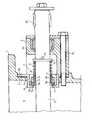
- the drawing shows only a partial sectional view through a pendulum flap designed according to the invention, specifically in the area of a housing wall penetrated by the flap shaft.
- the pendulum flap contains a flap housing 1, a flap shaft 2, which is guided to the outside through the flap housing wall 3, a seal 4 and a bearing 6 lying outside the housing interior 5; the shaft end 2a projecting axially outward from the bearing 6 can be connected in the usual way to a drive device (not illustrated in any more detail).
- An essential part of this invention is the design and arrangement of the seal 4, which seals the housing interior 5 at the passage point of the shaft 2 through the housing wall 3.
- This seal 4 initially contains as an essential component a slip ring 7, which surrounds the shaft 2 at a distance and is made of a suitable, temperature-resistant material (e.g. temperature-resistant steel) plane-ground sealing surface 7a, while on its axially opposite side it has a spherical bearing surface 7b.
- a suitable, temperature-resistant material e.g. temperature-resistant steel
- the slip ring 7 stands in Sealing sliding engagement with a likewise flat-ground, annular counter-sealing surface 8a of a cup wheel 8 which surrounds the shaft 2 at a distance and which is installed in a corresponding opening 3a in the housing wall 3.
- the spherical bearing surface 7b of the slip ring 7, is in engagement with a suitably designed spherical recess 9a of a pressure ring 9 surrounding the shaft 2 with little play.
- the pressure ring 9 is under the action of a compression spring 10, which is preferably designed as a temperature-resistant, cylindrical helical spring, arranged between two rings 11, 12 surrounding the shaft 2 and secured in its pretension by a cross pin 13 penetrating the shaft 2.
- a compression spring 10 which is preferably designed as a temperature-resistant, cylindrical helical spring, arranged between two rings 11, 12 surrounding the shaft 2 and secured in its pretension by a cross pin 13 penetrating the shaft 2.
- the compression spring 10 does not act directly on the pressure ring 9, but with the interposition of a static sealing element 14, which is accommodated in a recess 9b of this pressure ring on the side of the pressure ring axially opposite the spherical recess 9a and a possibly existing annular gap between shaft 2 and pressure ring 9 seals.
- This static sealing element is preferably formed by an asbestos-molykote fabric ring 14 which - as the drawing clearly shows - has the outer shape of a truncated cone in the axial direction, while the pressure ring recess 9b accordingly has a shape corresponding thereto.
- the static sealing fabric ring 14 is therefore always sufficient the preload pressed into the compression ring recess 9b; At the same time, the necessary pressure is then exerted on the pressure ring 9 itself, which in turn transmits this pressure to the slip ring 7, so that this slip ring 7 with its plane-ground sealing surface 7a always lies sufficiently firmly against the counter-sealing surface 8a of the cup wheel 8.
- the bearing 6, which is arranged further outside the housing interior 5 with respect to the seal, can be screwed to the housing wall 3 by means of screws 15 through its housing 6a together with the outer flange 8b of the cup wheel 8.
- the particularly dust and temperature protected bearing 6 in this outer arrangement is preferably designed as a radial joint bearing, so that it can compensate for any misalignment particularly well.
- the latter is particularly advantageous also in connection with the seal 4 according to the invention, in which a possible relative displacement of the slip ring 7 and pressure ring 9 due to the spherical bearing surfaces 7b and 9a balanced between shaft 3 and housing 1 and thus always a reliable seal between slip ring 7 and cup 8 (on their sealing surfaces 7a and 8a) is maintained.
Landscapes
- Engineering & Computer Science (AREA)
- General Engineering & Computer Science (AREA)
- Mechanical Engineering (AREA)
- Sealing Of Bearings (AREA)
- Sealing Devices (AREA)
Applications Claiming Priority (2)
| Application Number | Priority Date | Filing Date | Title |
|---|---|---|---|
| DE7922692 | 1979-08-08 | ||
| DE7922692U | 1979-08-08 |
Publications (1)
| Publication Number | Publication Date |
|---|---|
| EP0023953A1 true EP0023953A1 (fr) | 1981-02-18 |
Family
ID=6706448
Family Applications (1)
| Application Number | Title | Priority Date | Filing Date |
|---|---|---|---|
| EP80103179A Withdrawn EP0023953A1 (fr) | 1979-08-08 | 1980-06-07 | Dispositif d'étanchéité et palier pour l'arbre d'un volet oscillant |
Country Status (4)
| Country | Link |
|---|---|
| EP (1) | EP0023953A1 (fr) |
| BR (1) | BR8004960A (fr) |
| ES (1) | ES8104126A1 (fr) |
| ZA (1) | ZA803042B (fr) |
Cited By (11)
| Publication number | Priority date | Publication date | Assignee | Title |
|---|---|---|---|---|
| EP0249831A3 (en) * | 1986-06-11 | 1988-09-07 | Hoechst Aktiengesellschaft | Safety rotary transmission |
| DE4444719A1 (de) * | 1994-12-15 | 1996-06-20 | Atd Antriebs Und Dichtungstech | Dichtungsvorrichtung für eine durch eine Wand geführte Welle |
| WO1996028680A1 (fr) * | 1995-03-14 | 1996-09-19 | Ksb Aktiengesellschaft | Dispositif de robinetterie |
| EP1306618A1 (fr) * | 2001-10-24 | 2003-05-02 | Sammet Dampers OY | Système de paliers pour la fermeture et le contrôle de clapets de conduits de cheminées |
| WO2006003016A1 (fr) * | 2004-07-07 | 2006-01-12 | Faurecia Abgastechnik Gmbh | Valve a clapet pour systeme de gaz d'echappement d'un vehicule a moteur |
| WO2006003017A1 (fr) * | 2004-07-07 | 2006-01-12 | Faurecia Abgastechnik Gmbh | Soupape a clapet pour le circuit d'echappement d'un vehicule automobile |
| WO2009053363A1 (fr) * | 2007-10-24 | 2009-04-30 | Continental Automotive Gmbh | Soupape |
| EP2113692A1 (fr) * | 2008-04-30 | 2009-11-04 | Friedrich Boysen GmbH & Co. KG | Soupape à clapet |
| CN104314399A (zh) * | 2014-09-23 | 2015-01-28 | 中国核电工程有限公司 | 门板支撑及动力缓冲装置 |
| US9188162B2 (en) | 2013-10-08 | 2015-11-17 | Kice Industries, Inc. | Bearing assembly with spacer for locating a seal sleeve |
| US9574610B2 (en) | 2013-10-08 | 2017-02-21 | Kice Industries, Inc. | Bearing assembly with outboard bearing support cartridge |
Citations (7)
| Publication number | Priority date | Publication date | Assignee | Title |
|---|---|---|---|---|
| US2222612A (en) * | 1938-07-25 | 1940-11-26 | Johnson Corp | Fluid seal construction |
| US2744774A (en) * | 1952-05-06 | 1956-05-08 | Shell Dev | Shaft-seal |
| US3070377A (en) * | 1957-10-19 | 1962-12-25 | Eickmann Karl | Sealing arrangement between relatively rotating parts in hydraulic and pneumatic motors, internal combustion engines and the like |
| US3749358A (en) * | 1971-04-01 | 1973-07-31 | C Bates | Valve having adjustable seating means |
| GB1451874A (en) * | 1973-02-05 | 1976-10-06 | Johnson Corp | Self-adjusting seal load compensator |
| US4022424A (en) * | 1975-09-29 | 1977-05-10 | General Electric Company | Shaft bearing and seals for butterfly valves |
| DE7922692U1 (de) * | 1979-11-08 | Polysius Ag, 4720 Beckum | Pendelklappe |
-
1980
- 1980-05-22 ZA ZA00803042A patent/ZA803042B/xx unknown
- 1980-06-07 EP EP80103179A patent/EP0023953A1/fr not_active Withdrawn
- 1980-08-07 BR BR8004960A patent/BR8004960A/pt unknown
- 1980-08-07 ES ES494052A patent/ES8104126A1/es not_active Expired
Patent Citations (7)
| Publication number | Priority date | Publication date | Assignee | Title |
|---|---|---|---|---|
| DE7922692U1 (de) * | 1979-11-08 | Polysius Ag, 4720 Beckum | Pendelklappe | |
| US2222612A (en) * | 1938-07-25 | 1940-11-26 | Johnson Corp | Fluid seal construction |
| US2744774A (en) * | 1952-05-06 | 1956-05-08 | Shell Dev | Shaft-seal |
| US3070377A (en) * | 1957-10-19 | 1962-12-25 | Eickmann Karl | Sealing arrangement between relatively rotating parts in hydraulic and pneumatic motors, internal combustion engines and the like |
| US3749358A (en) * | 1971-04-01 | 1973-07-31 | C Bates | Valve having adjustable seating means |
| GB1451874A (en) * | 1973-02-05 | 1976-10-06 | Johnson Corp | Self-adjusting seal load compensator |
| US4022424A (en) * | 1975-09-29 | 1977-05-10 | General Electric Company | Shaft bearing and seals for butterfly valves |
Cited By (16)
| Publication number | Priority date | Publication date | Assignee | Title |
|---|---|---|---|---|
| EP0249831A3 (en) * | 1986-06-11 | 1988-09-07 | Hoechst Aktiengesellschaft | Safety rotary transmission |
| DE4444719A1 (de) * | 1994-12-15 | 1996-06-20 | Atd Antriebs Und Dichtungstech | Dichtungsvorrichtung für eine durch eine Wand geführte Welle |
| WO1996028680A1 (fr) * | 1995-03-14 | 1996-09-19 | Ksb Aktiengesellschaft | Dispositif de robinetterie |
| FR2731766A1 (fr) * | 1995-03-14 | 1996-09-20 | Ksb Ag | Dispositif de robinetteries |
| US6022000A (en) * | 1995-03-14 | 2000-02-08 | Ksb Aktiengesellschaft | Valve device |
| EP1306618A1 (fr) * | 2001-10-24 | 2003-05-02 | Sammet Dampers OY | Système de paliers pour la fermeture et le contrôle de clapets de conduits de cheminées |
| US7503544B2 (en) | 2004-07-07 | 2009-03-17 | Faurecia Abgastechnic Gmbh | Flap valve for a motor vehicle exhaust system |
| WO2006003017A1 (fr) * | 2004-07-07 | 2006-01-12 | Faurecia Abgastechnik Gmbh | Soupape a clapet pour le circuit d'echappement d'un vehicule automobile |
| WO2006003016A1 (fr) * | 2004-07-07 | 2006-01-12 | Faurecia Abgastechnik Gmbh | Valve a clapet pour systeme de gaz d'echappement d'un vehicule a moteur |
| WO2009053363A1 (fr) * | 2007-10-24 | 2009-04-30 | Continental Automotive Gmbh | Soupape |
| US8291885B2 (en) | 2007-10-24 | 2012-10-23 | Continental Automotive Gmbh | Valve having a sleeve to prevent contamination and condensation |
| CN101836019B (zh) * | 2007-10-24 | 2013-06-26 | 大陆汽车有限责任公司 | 阀门 |
| EP2113692A1 (fr) * | 2008-04-30 | 2009-11-04 | Friedrich Boysen GmbH & Co. KG | Soupape à clapet |
| US9188162B2 (en) | 2013-10-08 | 2015-11-17 | Kice Industries, Inc. | Bearing assembly with spacer for locating a seal sleeve |
| US9574610B2 (en) | 2013-10-08 | 2017-02-21 | Kice Industries, Inc. | Bearing assembly with outboard bearing support cartridge |
| CN104314399A (zh) * | 2014-09-23 | 2015-01-28 | 中国核电工程有限公司 | 门板支撑及动力缓冲装置 |
Also Published As
| Publication number | Publication date |
|---|---|
| ES494052A0 (es) | 1981-04-01 |
| ZA803042B (en) | 1981-05-27 |
| BR8004960A (pt) | 1981-02-17 |
| ES8104126A1 (es) | 1981-04-01 |
Similar Documents
| Publication | Publication Date | Title |
|---|---|---|
| DE69808027T2 (de) | Drehende, hin- und hergehende Abdichtung mit Metallinnenband | |
| DE69216943T2 (de) | Drehbare Rohrverbindung mit verbesserter Dichtung | |
| EP0023953A1 (fr) | Dispositif d'étanchéité et palier pour l'arbre d'un volet oscillant | |
| DE2644419A1 (de) | Antriebszapfenabdichtung eines kugelhahns | |
| DE3907294A1 (de) | Universalkugelverbindung | |
| DE4004094A1 (de) | Verschlussvorrichtung fuer eine rohrleitung zum transport von losen produkten | |
| DE3819566C2 (fr) | ||
| DE102018122000B4 (de) | Wellendichtung mit einem Wellendichtring | |
| DE2151076C3 (de) | Drehvorrichtung | |
| DE2814486A1 (de) | Drehschieber zur steuerung der stroemung eines festen, teilchenfoermigen materials | |
| DE1162144B (de) | Gleitringdichtung | |
| DE69924891T2 (de) | Lackpumpvorrichtung | |
| DE7922692U1 (de) | Pendelklappe | |
| CH650063A5 (de) | Kreiselpumpe mit einem aussengehaeuse und einem innengehaeuse. | |
| EP1125619A1 (fr) | Système pour le passage de la vapeur pour un évaporateur rotatif et évaporateur rotatif | |
| DE10157934A1 (de) | Buchse zur Einschränkung einer Bewegung eines Kugelgelenks | |
| DE7829170U1 (de) | Doppelt wirkende Gummibalgdichtung | |
| DE3607736C2 (de) | Absperrklappe | |
| DE2361332C3 (de) | Zwischen einem Kugelküken und einer den Durchflußkanal eines Kugelhahns umgebenden Gehäusedichtfläche angeordnete Ringdichtung | |
| DE3704634A1 (de) | Kugelhahn | |
| DE8913206U1 (de) | Drehrichtungsunabhängige Gleitringdichtung | |
| DE3008491A1 (de) | Gleitringdichtung | |
| EP0192179B1 (fr) | Mélangeur | |
| DE3520430A1 (de) | Gleitring fuer eine gleitringdichtung | |
| DE2455093A1 (de) | Kugelventil |
Legal Events
| Date | Code | Title | Description |
|---|---|---|---|
| PUAI | Public reference made under article 153(3) epc to a published international application that has entered the european phase |
Free format text: ORIGINAL CODE: 0009012 |
|
| AK | Designated contracting states |
Designated state(s): BE DE FR GB |
|
| STAA | Information on the status of an ep patent application or granted ep patent |
Free format text: STATUS: THE APPLICATION IS DEEMED TO BE WITHDRAWN |
|
| 18D | Application deemed to be withdrawn |
Effective date: 19820125 |
|
| RIN1 | Information on inventor provided before grant (corrected) |
Inventor name: BECKER, WILLI Inventor name: REGENTE, WERNER Inventor name: PRINZ, HELMUT Inventor name: GENAU, HANS Inventor name: UETER, JOHANNES |