EP0024043A2 - Apparat zum Umwandeln einer Drehbewegung in eine Längsbewegung - Google Patents
Apparat zum Umwandeln einer Drehbewegung in eine Längsbewegung Download PDFInfo
- Publication number
- EP0024043A2 EP0024043A2 EP80104672A EP80104672A EP0024043A2 EP 0024043 A2 EP0024043 A2 EP 0024043A2 EP 80104672 A EP80104672 A EP 80104672A EP 80104672 A EP80104672 A EP 80104672A EP 0024043 A2 EP0024043 A2 EP 0024043A2
- Authority
- EP
- European Patent Office
- Prior art keywords
- screw
- nut
- thread
- motion
- frame
- Prior art date
- Legal status (The legal status is an assumption and is not a legal conclusion. Google has not performed a legal analysis and makes no representation as to the accuracy of the status listed.)
- Withdrawn
Links
- 238000005096 rolling process Methods 0.000 claims abstract description 4
- 230000000694 effects Effects 0.000 claims description 3
- 238000006243 chemical reaction Methods 0.000 abstract 1
- 230000008878 coupling Effects 0.000 description 2
- 238000010168 coupling process Methods 0.000 description 2
- 238000005859 coupling reaction Methods 0.000 description 2
- 238000004880 explosion Methods 0.000 description 2
Images
Classifications
-
- F—MECHANICAL ENGINEERING; LIGHTING; HEATING; WEAPONS; BLASTING
- F16—ENGINEERING ELEMENTS AND UNITS; GENERAL MEASURES FOR PRODUCING AND MAINTAINING EFFECTIVE FUNCTIONING OF MACHINES OR INSTALLATIONS; THERMAL INSULATION IN GENERAL
- F16H—GEARING
- F16H25/00—Gearings comprising primarily only cams, cam-followers and screw-and-nut mechanisms
- F16H25/18—Gearings comprising primarily only cams, cam-followers and screw-and-nut mechanisms for conveying or interconverting oscillating or reciprocating motions
- F16H25/20—Screw mechanisms
- F16H25/22—Screw mechanisms with balls, rollers, or similar members between the co-operating parts; Elements essential to the use of such members
- F16H25/2285—Screw mechanisms with balls, rollers, or similar members between the co-operating parts; Elements essential to the use of such members with rings engaging the screw shaft with the inner perimeter, e.g. using inner rings of a ball bearing
- F16H25/229—Eccentric rings with their axis arranged substantially parallel to the screw shaft axis
Definitions
- the present invention concerns an apparatus serving to convert rotary into linear motion, comprising a screw with exterior thread and, fitted thereupon, a nut or equivalent with interior thread, the two together presenting a certain radial play, and further comprising means for displacing the screw and nut to be eccentrically positioned with reference to each other.
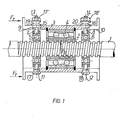
- the screw and nut are rotatably carried in a frame or equivalent in such manner that by rotating the screw one achieves a rolling between the screw and nut and thereby an axial movement owing to the pitch of the screw.
- the force Fs which is active in the radial direction of the nut 2 will also increase even though the thread is a flat thread, because by effect of the spring force the thread flanks of the nut must unavoidably penetrate owing to the rotary motion against the friction into the grooves of the screw's thread.
- the springs 19 and 20 will yield and the centre-line of the nut 2 will move closer to the centre-line of the screw 1, causing the above- mentioned lag to be reduced, and ultimately_at the force Frmax, the said centre-line will coincide.
- the lag has then gone down to zero and the motion of the nut 2 in the axial direction of the screw has stopped even though the screw 1 is rotating because nut and screw are then rotating with equal speeds.
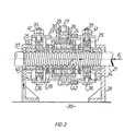
- Another possibility is: to take the force off from the non-rotating screw, in which case the frame is rotated, and the nut is elastically affixed to the frame, as shown in Fig. 2.
- the screw 21 is in this example non rotating and is thus only free to move longitudinally.
- the nut 22 has been affixed to the frame 23 by the bearing arrangement 24, the frame being rotated.
- the bearings 25 stay the frame with the aid of sleeves 33 against the screw 21.
- the bearings 26 take upthe axial force which is transmitted along the interrupted line drawn in Fig. 2, from the stationary base over the bearing stands 38, sleeves 37, bearings 26 and nut 22 to the screw 21. It should be noted here that this force passes through the bearing 26 only, and no losses due to the axial force are incurred in any other bearings.
- the bearing 26 only transmits a very slow rotary motion, whereby the bearing losses caused by the axial useful force Fr are exceedingly low.
- the carrying surfaces of the bearings 26 along which the balls roll are plain, that is without groove, and for this reason the nut 22 may freely move in radial direction, whereby the nut 22 can be urged with ease by the aid of the screw 27, with the aid of sleeves 28 and 29 and springs 30 and the sleeve 31, elastically against the screw 21.
- the sleeves 33 guide the screw 21 and they are affixed to the inner circumference of the bearings 25 with close fit, with the aid of radial projections 34 passing through the sleeve 37, these bearings 25 in their turn being turnably affixed to the frame 23 with the aid of pins 35 and 36 and sleeves 43.
- the sleeves 37 transmit the axial force from the bearing stands 38 and from the base 39 to the other half of the bearing 26.
- the sleeves 40 maintain the screw radially in its place with reference to the base 39.
- the nut 41 is used to centre the screw 21 in the frame.
- the ring 42 is a.belt pulley, the nut being rotated e.g. with a motor over this pulley and a belt.
- the sleeves 33 When with the aid of the screws 27 the nut is urged tight against the screw with its one side, the sleeves 33 will correspondingly be urged fast to the flank of the screw on the opposite side, guided by the pins 35 and 36 and by the bearings 25.
- the sleeves 33 may move both axially and radially to the screw 21 within the sleeve 37, whereby the sleeve 33 transmits only the radial force 23 to the screw 21, not the axial force which goes from the nut over the sleeve 37 to the bearing stand.
- the above mentioned play also permits wearing down of the sleeve 33 without such wearing causing any increase of eccentricity with regard to the screw, giving rise to vibration as the screw is rotated.
- both rings of the bearing 26 have only a very low speed of rotation relative to each other; in addition, one ring moves with reference to the other along a circular path, the radius of this circle equalling the distance between the screw and nut centre-lines.
- the other ring of the bearing 26 does not rotate, it being affixed to the sleeve 37, which is integral with the screw. The screw moves in its axial direction without rotating, and the useful force may be taken off therefrom.
- the shape of the thread may also be another than a flat thread, but in that case the force deflecting the nut must generally be higher, related to the axial useful force, because the flank angle of the thread gives rise to a radial extra force acting on the nut.
- the best thread form is believed to be a flat thread because in that case the radial force is low and, as experience has thaught,-the risk of vibration of the nut is also minimized.
Landscapes
- Engineering & Computer Science (AREA)
- General Engineering & Computer Science (AREA)
- Mechanical Engineering (AREA)
- Transmission Devices (AREA)
Applications Claiming Priority (2)
| Application Number | Priority Date | Filing Date | Title |
|---|---|---|---|
| FI792472 | 1979-08-09 | ||
| FI792472A FI792472A7 (fi) | 1979-08-09 | 1979-08-09 | Siirtomutteri. |
Publications (2)
| Publication Number | Publication Date |
|---|---|
| EP0024043A2 true EP0024043A2 (de) | 1981-02-18 |
| EP0024043A3 EP0024043A3 (de) | 1981-03-18 |
Family
ID=8512816
Family Applications (1)
| Application Number | Title | Priority Date | Filing Date |
|---|---|---|---|
| EP80104672A Withdrawn EP0024043A3 (de) | 1979-08-09 | 1980-08-07 | Apparat zum Umwandeln einer Drehbewegung in eine Längsbewegung |
Country Status (3)
| Country | Link |
|---|---|
| EP (1) | EP0024043A3 (de) |
| DK (1) | DK339180A (de) |
| FI (1) | FI792472A7 (de) |
Cited By (4)
| Publication number | Priority date | Publication date | Assignee | Title |
|---|---|---|---|---|
| GB2211908A (en) * | 1987-10-31 | 1989-07-12 | Jaguar Cars | Linear actuator |
| EP1801457A4 (de) * | 2004-09-16 | 2008-01-16 | Scient Technologies Ltd | Verfahren und vorrichtung zur kraftübertragung mit lasterfassungs-schubverstärkungsmechanismus |
| EP2107274A1 (de) * | 2008-03-31 | 2009-10-07 | Nozag AG | Wälzelement und Getriebe zur Umwandlung einer Drehbewegung in eine Längsbewegung |
| CN116550099A (zh) * | 2023-04-18 | 2023-08-08 | 山西炬华铝业股份有限公司 | 一种高温酸雾回收利用装置 |
Family Cites Families (5)
| Publication number | Priority date | Publication date | Assignee | Title |
|---|---|---|---|---|
| US2556572A (en) * | 1944-08-23 | 1951-06-12 | William A Brinkhurst | Screw feed |
| US2918827A (en) * | 1957-03-01 | 1959-12-29 | Gen Electric | Linear actuator |
| US3614900A (en) * | 1970-05-08 | 1971-10-26 | Wahlmark Systems | Anti-friction drive |
| US3730016A (en) * | 1971-06-14 | 1973-05-01 | Continental Can Co | Friction drive differential screw |
| DE2261736A1 (de) * | 1972-12-16 | 1974-06-20 | Wilhelm Dipl-Ing Dozler | Schraubgetriebe |
-
1979
- 1979-08-09 FI FI792472A patent/FI792472A7/fi not_active Application Discontinuation
-
1980
- 1980-08-07 EP EP80104672A patent/EP0024043A3/de not_active Withdrawn
- 1980-08-07 DK DK339180A patent/DK339180A/da unknown
Cited By (5)
| Publication number | Priority date | Publication date | Assignee | Title |
|---|---|---|---|---|
| GB2211908A (en) * | 1987-10-31 | 1989-07-12 | Jaguar Cars | Linear actuator |
| EP1801457A4 (de) * | 2004-09-16 | 2008-01-16 | Scient Technologies Ltd | Verfahren und vorrichtung zur kraftübertragung mit lasterfassungs-schubverstärkungsmechanismus |
| US7584678B2 (en) | 2004-09-16 | 2009-09-08 | Scientific Technologies Ltd. | Power transmission method and device having load sensing thrust augmentation mechanism |
| EP2107274A1 (de) * | 2008-03-31 | 2009-10-07 | Nozag AG | Wälzelement und Getriebe zur Umwandlung einer Drehbewegung in eine Längsbewegung |
| CN116550099A (zh) * | 2023-04-18 | 2023-08-08 | 山西炬华铝业股份有限公司 | 一种高温酸雾回收利用装置 |
Also Published As
| Publication number | Publication date |
|---|---|
| FI792472A7 (fi) | 1981-01-01 |
| DK339180A (da) | 1981-02-10 |
| EP0024043A3 (de) | 1981-03-18 |
Similar Documents
| Publication | Publication Date | Title |
|---|---|---|
| US4813303A (en) | Power drive speed reducer | |
| US4576057A (en) | Anti-friction nut/screw drive | |
| US4593574A (en) | Torque-dependent pressure mechanism for continuously adjustable ball-type planetary gear set | |
| SE435685B (sv) | Konkross | |
| US20210269085A1 (en) | Electromechanical actuator and rear-axle steering system | |
| EP0013074A1 (de) | Zahnstangegetriebe mit veränderlichem Übersetzungsverhältnis | |
| JP2000506447A (ja) | 動力ナットランナー | |
| IE43729B1 (en) | Hoisting device | |
| JP3853369B2 (ja) | 回転運動を軸方向運動に変換する装置 | |
| US3105397A (en) | Step-down transmission mechanisms | |
| US4730516A (en) | Drive apparatus for auxiliary equipment responsive to a charging generator speed representing signal | |
| US6299101B1 (en) | Adjusting apparatus for control surfaces of a missile | |
| US3324746A (en) | Steplessly controlled differential reducer coupling | |
| WO1997021524A1 (en) | Portable hand complex machine | |
| US4742896A (en) | Brake means | |
| RU2376513C1 (ru) | Электропривод вращательного движения | |
| GB2211908A (en) | Linear actuator | |
| KR100784045B1 (ko) | 무단변속장치 | |
| US6168110B1 (en) | Dual bobbin mandrel | |
| US4138900A (en) | Speed change device | |
| SU1511000A1 (ru) | Электромеханический привод зажима Барановского В.В. | |
| RU82282U1 (ru) | Регулируемый мотор-вариатор | |
| SU1516683A1 (ru) | Шариковинтовой механизм | |
| FI81325B (fi) | Elektriskt lyftblock. | |
| US4691595A (en) | Planetary transmission based on friction |
Legal Events
| Date | Code | Title | Description |
|---|---|---|---|
| PUAI | Public reference made under article 153(3) epc to a published international application that has entered the european phase |
Free format text: ORIGINAL CODE: 0009012 |
|
| PUAL | Search report despatched |
Free format text: ORIGINAL CODE: 0009013 |
|
| AK | Designated contracting states |
Designated state(s): CH DE FR GB NL SE |
|
| AK | Designated contracting states |
Designated state(s): CH DE FR GB NL SE |
|
| STAA | Information on the status of an ep patent application or granted ep patent |
Free format text: STATUS: THE APPLICATION HAS BEEN WITHDRAWN |
|
| 18W | Application withdrawn |
Withdrawal date: 19810922 |