EP0024165A1 - Récipient pour liquides pouvant être empilé de deux manières différentes - Google Patents
Récipient pour liquides pouvant être empilé de deux manières différentes Download PDFInfo
- Publication number
- EP0024165A1 EP0024165A1 EP80302702A EP80302702A EP0024165A1 EP 0024165 A1 EP0024165 A1 EP 0024165A1 EP 80302702 A EP80302702 A EP 80302702A EP 80302702 A EP80302702 A EP 80302702A EP 0024165 A1 EP0024165 A1 EP 0024165A1
- Authority
- EP
- European Patent Office
- Prior art keywords
- container
- spout
- recess
- vertical
- containers
- Prior art date
- Legal status (The legal status is an assumption and is not a legal conclusion. Google has not performed a legal analysis and makes no representation as to the accuracy of the status listed.)
- Granted
Links
- 239000007788 liquid Substances 0.000 title claims description 8
- 238000012856 packing Methods 0.000 abstract 1
- 239000000463 material Substances 0.000 description 3
- 229920003023 plastic Polymers 0.000 description 3
- 239000004033 plastic Substances 0.000 description 3
- 230000000295 complement effect Effects 0.000 description 1
- 239000012528 membrane Substances 0.000 description 1
- 239000002184 metal Substances 0.000 description 1
- 239000008267 milk Substances 0.000 description 1
- 210000004080 milk Anatomy 0.000 description 1
- 235000013336 milk Nutrition 0.000 description 1
- 230000002787 reinforcement Effects 0.000 description 1
- 238000007789 sealing Methods 0.000 description 1
- 238000000926 separation method Methods 0.000 description 1
Images


Classifications
-
- B—PERFORMING OPERATIONS; TRANSPORTING
- B65—CONVEYING; PACKING; STORING; HANDLING THIN OR FILAMENTARY MATERIAL
- B65D—CONTAINERS FOR STORAGE OR TRANSPORT OF ARTICLES OR MATERIALS, e.g. BAGS, BARRELS, BOTTLES, BOXES, CANS, CARTONS, CRATES, DRUMS, JARS, TANKS, HOPPERS, FORWARDING CONTAINERS; ACCESSORIES, CLOSURES, OR FITTINGS THEREFOR; PACKAGING ELEMENTS; PACKAGES
- B65D21/00—Nestable, stackable or joinable containers; Containers of variable capacity
- B65D21/02—Containers specially shaped, or provided with fittings or attachments, to facilitate nesting, stacking, or joining together
- B65D21/0209—Containers specially shaped, or provided with fittings or attachments, to facilitate nesting, stacking, or joining together stackable or joined together one-upon-the-other in the upright or upside-down position
- B65D21/023—Closed containers provided with local cooperating elements in the top and bottom surfaces, e.g. projection and recess
- B65D21/0231—Bottles, canisters or jars whereby the neck or handle project into a cooperating cavity in the bottom
Definitions
- the present invention relates to a container for liquids of the type having a spout on the top to assist dispensing of the liquid therein.
- Containers having pouring spouts on the top are well known.
- the pouring spouts may be located at the centre of the top of the container or adjacent the side edge of the container. Some spouts are even rotatable.
- One of the oil companies has come out with a new type of oil can or container with a spout in the centre of the top, the spout in the centre of the top, the spout being provided to assist in pouring for the filling of lawnmowers or the like.
- spouted containers can sometimes be inconvenient from the standpoint of handling, stacking, shipping etc.
- the present invention provides a spouted container which can be stacked with others, e.g. for display purposes, in substantially the same manner as unspouted containers except that the spout on the uppermost container of a vertical stack will project above that uppermost container.
- the containers can be stacked and shipped in exactly the same manner as unspouted containers, without any projection of the spouts.
- a container for holding liquids comprising a substantially vertical wall means closed at the top by a substantially flat top and closed at the bottom by a substantially flat bottom thereby defining a hollow container, a vertically directed hollow pouring spout extending upwardly from the top of said container adjacent said wall means and in communication with the interior of said container, and means for closing the end of said spout characterised by a first recess in the bottom of the container adjacent said wall means for receiving therein the spout of another underlying and upright container as defined above, and a second recess located in the top of the container adjacent said wall means for receiving therein the spout of a super-imposed and inverted container as defined above while the spout of the given container is simultaneously received in the second recess in said super-imposed and inverted container.
- the first and-second may extend recesses into each other to form a single recess extending for the full vertical height of the container in substantially parallel relation to the vertical axis of the container
- At least one projection may be located at the top of the container and the bottom provided with a corresponding recess or recesses.
- the relationship between the projections, or projections and the recess or recesses is such that, when one container is super-imposed in upright position over a second container also in upright position, the or each projection on the lower container will be received in the or each recess in the bottom of the overlying container while the spout of the lower container will be simultaneously received in the said second recess of the overlying container, as described above.
- the spouts of the two containers are mutually received within the first recesses provided at the intermating tops of the two containers.
- the projections of the two containers may interfit in this position, the container may be cylindrical or may be cubic with the spout located adjacent one corner at the top of the container.
- the corner of the cubic container diagonally opposite to the spout may be the location for the first and second recesses which accommodate the spouts of other containers for upright or inverted stacking.
- this said opposite corner may be provided with a cut-out portion so as to form a handle, and the portion of the corner which encloses the cut-out portion may be thickened so as to reinforce the handle.
- the cubic container is also provided with said nesting projections and recesses at the bottom; however.
- the cubic container could be provided in gallon and half-gallon sizes for milk, or the like.
- the cubic container can be stacked in substantially the same manner as the cylindrical container described above, in which case the spouts which are received in the recesses of the adjacent containers do not extend beyond the perimeters of the containers.
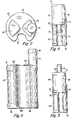
- Figure 1 shows a generally cylindrical container (or can) 10 having a generally flat top 12 and a generally flat bottom 13.
- the container 10 is preferably made of plastics material which is commonly employed to make cans, jars, bottles or the like for holding liquid therein.
- a substantially cylindrical pouring spout 14 is located at the top of the container adjacent the edge thereof as shown in Figures 1 and 2.
- the pouring spout 14 is hollow and communicates with the hollow interior of the container 10.
- the spout 14 is closed by a cap 16, which in the case of Figures 1 to 4 is threadedly received on the top of the spout 14.
- the spout 14 can be closed by a sheet or membrane of plastics material (not shown) which can be perforated, cut,or otherwise removed to permit pouring of the contents from the can 10 through the pouring spout 14.
- a curved recess 18 is provided along one side of the container and extends from the top to the bottom thereof substantially parallel to the central axis of the cylindrical surface of the container 10. The inner portion of the curved recess 18 is of substantially the same shape and diameter as the spout 14, for a purpose described hereinafter.
- Figure 3 shows two containers or cans 10 stacked in upright position in such a manner that the spout 14 of the lowermost container 10 is received in the lower portion of the recess 18 of the upper container 10.
- the spout 14 of the uppermost container 10 projects above the assembly as shown.
- a pair of pie-shaped (i.e. substantially quadrant-shaped) raised portions 20 and 22 are provided on the top 12 of the container 10.
- One of these pie-shaped raised portions 22 surrounds and connects with or merges with the base of the spout 14.
- the bottom 13 of the container 10 is similarly provided with a pair of pie-shaped recesses 24 and 26 which best appear in Figure 8 which shows a modified form of the container 10'.
- Each of the raised portions 20 and 22 and each of the recessed portions 4 and 26 occupy about 90° of the surface of the top of bottom of the can, respectively, and these raised portions and recesses are symmetrically arranged on the top and bottom, as shown.
- the longitudinal recess 18 is located about 90° away from the spout 14 as related to the cylindrical configuration of the container 10.
- Figure 4 shows a condition where two containers 10 are arranged in a nesting relation whereby the upper container 10 is inverted with respect to the lower container 10; in this instance, the spout 14 of the upper container 10 is received in the upper portion of the recess 18 of the lower container 10, whereas the spout 14 of the lower container 10 is received in the lower portion of the now inverted recess 18 of the upper container 10.
- the now downwardly directed pie-shaped projections 20 and 22 of the upper inverted container 10 will be received in the spaces between the raised projections 20 and 22 of the lower container 10, such that there is a slight separation 27 between the two containers as shown in Figure 4.
- the bottom 13 of the upper container 10 in Figure 3 fits nicely against the upper surface 12 of the lower container 10 in view of the intermating relationships between the projections 20 and 22 on the lower container and the recesses 24 and 26 on the bottom of the upper container 10.
- the container 10' shown in Figures 5 to 8 is a slightly modified form of the container 10 shown in Figures 1 to 4.
- These recesses 28 and 30 do not continue or extend for the full height of the container 10' but are separated from each other by an intermediate radial portion 32 which extends out to the normal diameter of the container 10'.
- the container 10' is otherwise the same as the container 10 described in relation to Figures 1 to 4.
- the spout 14 on the lowermost container 10' would be received in the recess 30 of the upper container 10'. If one were to stack the containers 10' of Figures 5 through 8 in the manner shown in Figure 4, the spout 14 of the lower container would be received in the recess 28 of the upper inverted container, whereas the inverted spout 14 of the upper container would be received in the upper recess 28 of the lower container. Otherwise, the stacking relationships of the container 10' would be exactly the same as that shown in Figures 3 and 4 for the container 10.
- the raised portions 20 and 22 fit into the recesses 26 and 24, respectively, so as to improve the nesting relationship; however, if the raised portions on the corresponding recesses were eliminated, such that the tops 12 and the bottoms 13 of the cans or containers 10 were substantially flat, it would not be necessary that the recess 30 be in alignment with the recess 28, because the location of the spout 14 on the uppermost can is wholly independent of the nesting of the lowermost spout 14 in the recess 30 in the upper container 10'.
- FIGS. 9 to 13 inclusive show a liquid container having a different cross sectional shape, i.e. square.
- This container 40 is provided with a generally flat top 42, a generally flat bottom 44 and four generally flat vertical sides 46, 48, 50 and 52.
- the container 40 is generally in the shape of a cube.
- a pouring spout 54 is located on the top 42 in the corner adjacent where the sides 50 and 52 come together.
- the pouring spout is provided with a cap 56 for sealing purposes.
- a recess 58 which is shaped so as to receive the spout 54 and cap 56 of a super-imposed and inverted container 40; when such an inverted container 40 is super-imposed on the given container 40 shown in Figure 11, the spout 54 and cap 56 will likewise fit into the recess 58 provided in the top of the inverted container.
- another recess 60 which is located directly below the recess 58.
- both recesses 58 and 60 are located along the corner of the container 40 formed by the merger of the side walls 46 and 48.
- This same corner is provided with an opening or cut-out portion 62 to provide a handle for lifting and pouring from the container 40.
- the portion of the corner which closes the opening 62 is thickened as at 64 to provide reinforcement for the resulting handle.
- the top 42 of the container 40 is provided with a pair of triangular raised portions 66 and 68 which are symmetrically spaced and which occupy each about 90° of the surface of the top 42.
- the bottom 44 of the container 40 is provided with a pair of triangular recesses 70 and 72 which are complementary to the raised portions 66 and 68. These recesses 70 and 72 also occupy approximately 90° each of the bottom 44 are symmetrically arranged.
- the triangular projections 66 and 68 in the top 42 of the lower container will fit into the recesses 70 and 72 in the bottom 44 of the overlying container.
- the spout 54 and the cap 56 of the upper inverted container will fit into the recess 58 on the top of the lower upright container, while the spout 54 and cap 56 of the lower container will simultaneously fit into the recess 58 in the top of the super-imposed and inverted container 40.
- the triangular projections 66 and 68 on the top of the super-imposed and inverted container will fit into the spaces between the recesses 66 and 68 on the top of the lower container.
- Figure 13 shows an arrangement where three containers 40 are stacked one on top of the other, with the lower two containers in the upright position and the uppermost container being inverted.
- any one of the spouted containers described above can be displayed and shipped in substantially the same manner as an unspouted container.
- the container can be made of plastics, metal or any other suitable material which has been used in the past for making containers.
- the container can be stacked two, three, four or more high in substantially the same way as unspouted containers, the only difference being that the uppermost container will have its spout projecting above this container.
- the container can be shipped two, three, four or more high in substantially the same manner as unspouted_containers and without requiring any more shipping space. Since the uppermost container in any given vertical row will be inverted, there will be no projecting spouts which might otherwise interfere with the shipment of such spouted containers.
- the spouts will be entirely contained within the boundaries defined by the outer vertical surfaces of the containers.
Landscapes
- Engineering & Computer Science (AREA)
- Mechanical Engineering (AREA)
- Stackable Containers (AREA)
- Details Of Rigid Or Semi-Rigid Containers (AREA)
- Packging For Living Organisms, Food Or Medicinal Products That Are Sensitive To Environmental Conditiond (AREA)
- Containers Having Bodies Formed In One Piece (AREA)
Priority Applications (1)
| Application Number | Priority Date | Filing Date | Title |
|---|---|---|---|
| AT80302702T ATE6047T1 (de) | 1979-08-10 | 1980-08-07 | Auf zwei verschiedene arten stapelbarer fluessigkeitsbehaelter. |
Applications Claiming Priority (2)
| Application Number | Priority Date | Filing Date | Title |
|---|---|---|---|
| US65540 | 1979-08-10 | ||
| US06/065,540 US4489839A (en) | 1979-08-10 | 1979-08-10 | Two-way nesting container for liquids |
Publications (2)
| Publication Number | Publication Date |
|---|---|
| EP0024165A1 true EP0024165A1 (fr) | 1981-02-25 |
| EP0024165B1 EP0024165B1 (fr) | 1984-02-01 |
Family
ID=22063427
Family Applications (1)
| Application Number | Title | Priority Date | Filing Date |
|---|---|---|---|
| EP80302702A Expired EP0024165B1 (fr) | 1979-08-10 | 1980-08-07 | Récipient pour liquides pouvant être empilé de deux manières différentes |
Country Status (7)
| Country | Link |
|---|---|
| US (1) | US4489839A (fr) |
| EP (1) | EP0024165B1 (fr) |
| JP (1) | JPS6031701B2 (fr) |
| AT (1) | ATE6047T1 (fr) |
| AU (1) | AU531427B2 (fr) |
| CA (1) | CA1146486A (fr) |
| DE (1) | DE3066397D1 (fr) |
Cited By (7)
| Publication number | Priority date | Publication date | Assignee | Title |
|---|---|---|---|---|
| GB2139592A (en) * | 1983-05-12 | 1984-11-14 | Cosden Technology | Container for flowable products |
| US4573595A (en) * | 1983-12-12 | 1986-03-04 | Universal Symetrics Corporation | Mated container units |
| EP0261573A1 (fr) * | 1986-09-22 | 1988-03-30 | Universal Symetrics Corporation | Bouteilles à goulot court et module combiné adapté |
| EP0197526A3 (fr) * | 1985-04-09 | 1988-07-27 | Universal Symetrics Corporation | Emballage constitué de récipients multiples |
| EP0266752A3 (fr) * | 1986-11-06 | 1989-03-22 | Universal Symetrics Corporation | Récipients à col allongé et rainure transverse servant à l'assemblage d'un ensemble |
| US7754138B1 (en) | 2006-07-10 | 2010-07-13 | Akira Kashiwase | Apparatus and method of manufacturing stackable containers |
| US8763826B1 (en) * | 2012-07-01 | 2014-07-01 | Dale Smith | Bottle design and method of making and using the same |
Families Citing this family (19)
| Publication number | Priority date | Publication date | Assignee | Title |
|---|---|---|---|---|
| USD279961S (en) | 1983-05-12 | 1985-08-06 | Cosden Technology, Inc. | Container for flowable products |
| USD279962S (en) | 1983-05-12 | 1985-08-06 | Cosden Technology, Inc. | Container for flowable products |
| US4671412A (en) * | 1985-11-06 | 1987-06-09 | Gatten Robert L | Stackable bottle |
| US4981214A (en) * | 1988-09-30 | 1991-01-01 | Rojas Albert R | Beverage container assembly |
| WO1992006897A1 (fr) * | 1990-10-12 | 1992-04-30 | Richard Henry Cooke | Recipient |
| US5329098A (en) * | 1992-09-11 | 1994-07-12 | Adams Industries, Inc. | Open coil heater for efficient transport |
| US5485920A (en) * | 1994-08-30 | 1996-01-23 | Fritz; Lawrence E. | Stackable space saving container |
| USD404302S (en) | 1996-06-14 | 1999-01-19 | Forrest Samuel Martin | Interlocking double bottle |
| US5823391A (en) * | 1996-09-04 | 1998-10-20 | Owens-Brockway Plastic Products Inc. | Dual chamber flexible tube dispensing package and method of making |
| US5779051A (en) * | 1996-09-09 | 1998-07-14 | Boutin; Raymond | Two-plane stacking container for liquids |
| USD414104S (en) | 1997-04-29 | 1999-09-21 | Owens-Brockway Plastic Products Inc. | Dual tube assembly |
| GB2372493A (en) * | 2001-02-23 | 2002-08-28 | Tetra Laval Holdings & Finance | Container |
| US7225937B2 (en) * | 2003-05-13 | 2007-06-05 | Schroeder Michael D | Package system |
| BRMU8400196U (pt) * | 2004-02-19 | 2005-10-11 | Ivo Amaral Campos | Disposição de uma cavidade cÈncava - cuja a borda tem a forma semelhante a uma ferradura - prensada nos frascos de plástico para acondicionamento de óleos lubrificantes em geral e lìquidos diversos |
| US20060151352A1 (en) * | 2005-01-11 | 2006-07-13 | Harrington Harry C Iv | Interconnecting container |
| USD571661S1 (en) | 2006-09-01 | 2008-06-24 | Ball Corporation | Bottle |
| US9462913B1 (en) * | 2010-01-20 | 2016-10-11 | Griffin Industries LLC | Liquid storage system |
| US20120292342A1 (en) * | 2011-05-18 | 2012-11-22 | Yehuda Bobrovsky | Apparatus and assemblies for storage and application of condiments |
| US20220144488A1 (en) * | 2020-11-11 | 2022-05-12 | Chalaina Sheringna Rawles | Separable multi-dispenser assembly |
Citations (8)
| Publication number | Priority date | Publication date | Assignee | Title |
|---|---|---|---|---|
| US2641374A (en) * | 1949-10-29 | 1953-06-09 | Yee Sing Chun | Container |
| DE1079538B (de) * | 1955-06-22 | 1960-04-07 | Continental Can Co | Stapelbarer Kanister |
| US3322262A (en) * | 1965-06-01 | 1967-05-30 | Leaming Plastics Inc | Moisture-tight container |
| FR1482875A (fr) * | 1966-02-18 | 1967-06-02 | Carnaud & Forges | Récipient empilable |
| FR2071495A5 (fr) * | 1969-12-31 | 1971-09-17 | Rohrbach Bernd | |
| US3765574A (en) * | 1973-02-16 | 1973-10-16 | I Urquiza | Container for liquids |
| US3782602A (en) * | 1973-03-14 | 1974-01-01 | M Page | Frozen water containers with liquid dispenser for camping |
| FR2299237A1 (fr) * | 1975-01-29 | 1976-08-27 | Oreal | Dispositif de conditionnement comportant deux enceintes separees |
Family Cites Families (3)
| Publication number | Priority date | Publication date | Assignee | Title |
|---|---|---|---|---|
| NL264970A (fr) * | 1960-05-24 | |||
| US3176879A (en) * | 1962-04-16 | 1965-04-06 | Mojonnier Inc Albert | Container with spout, handle and a depression in its bottom wall for stacking |
| US3889834A (en) * | 1973-10-25 | 1975-06-17 | Foremost Mckesson | Container construction |
-
1979
- 1979-08-10 US US06/065,540 patent/US4489839A/en not_active Expired - Lifetime
-
1980
- 1980-08-01 CA CA000357527A patent/CA1146486A/fr not_active Expired
- 1980-08-07 EP EP80302702A patent/EP0024165B1/fr not_active Expired
- 1980-08-07 AT AT80302702T patent/ATE6047T1/de not_active IP Right Cessation
- 1980-08-07 AU AU61158/80A patent/AU531427B2/en not_active Ceased
- 1980-08-07 DE DE8080302702T patent/DE3066397D1/de not_active Expired
- 1980-08-11 JP JP55110970A patent/JPS6031701B2/ja not_active Expired
Patent Citations (8)
| Publication number | Priority date | Publication date | Assignee | Title |
|---|---|---|---|---|
| US2641374A (en) * | 1949-10-29 | 1953-06-09 | Yee Sing Chun | Container |
| DE1079538B (de) * | 1955-06-22 | 1960-04-07 | Continental Can Co | Stapelbarer Kanister |
| US3322262A (en) * | 1965-06-01 | 1967-05-30 | Leaming Plastics Inc | Moisture-tight container |
| FR1482875A (fr) * | 1966-02-18 | 1967-06-02 | Carnaud & Forges | Récipient empilable |
| FR2071495A5 (fr) * | 1969-12-31 | 1971-09-17 | Rohrbach Bernd | |
| US3765574A (en) * | 1973-02-16 | 1973-10-16 | I Urquiza | Container for liquids |
| US3782602A (en) * | 1973-03-14 | 1974-01-01 | M Page | Frozen water containers with liquid dispenser for camping |
| FR2299237A1 (fr) * | 1975-01-29 | 1976-08-27 | Oreal | Dispositif de conditionnement comportant deux enceintes separees |
Cited By (8)
| Publication number | Priority date | Publication date | Assignee | Title |
|---|---|---|---|---|
| GB2139592A (en) * | 1983-05-12 | 1984-11-14 | Cosden Technology | Container for flowable products |
| US4573595A (en) * | 1983-12-12 | 1986-03-04 | Universal Symetrics Corporation | Mated container units |
| EP0145425A3 (en) * | 1983-12-12 | 1986-12-17 | Universal Symetrics, Incorporated | Mated container units |
| EP0197526A3 (fr) * | 1985-04-09 | 1988-07-27 | Universal Symetrics Corporation | Emballage constitué de récipients multiples |
| EP0261573A1 (fr) * | 1986-09-22 | 1988-03-30 | Universal Symetrics Corporation | Bouteilles à goulot court et module combiné adapté |
| EP0266752A3 (fr) * | 1986-11-06 | 1989-03-22 | Universal Symetrics Corporation | Récipients à col allongé et rainure transverse servant à l'assemblage d'un ensemble |
| US7754138B1 (en) | 2006-07-10 | 2010-07-13 | Akira Kashiwase | Apparatus and method of manufacturing stackable containers |
| US8763826B1 (en) * | 2012-07-01 | 2014-07-01 | Dale Smith | Bottle design and method of making and using the same |
Also Published As
| Publication number | Publication date |
|---|---|
| ATE6047T1 (de) | 1984-02-15 |
| JPS6031701B2 (ja) | 1985-07-24 |
| EP0024165B1 (fr) | 1984-02-01 |
| CA1146486A (fr) | 1983-05-17 |
| DE3066397D1 (en) | 1984-03-08 |
| US4489839A (en) | 1984-12-25 |
| AU6115880A (en) | 1981-02-12 |
| JPS5632232A (en) | 1981-04-01 |
| AU531427B2 (en) | 1983-08-25 |
Similar Documents
| Publication | Publication Date | Title |
|---|---|---|
| US4489839A (en) | Two-way nesting container for liquids | |
| US5002199A (en) | Stackable bottle | |
| EP0145425B1 (fr) | Unité de récipients juxtaposés | |
| US3369658A (en) | Portable container transport unit | |
| US8328014B2 (en) | Multiple sealed beverage vessels in a case | |
| US4877142A (en) | Rectangular bottle for motor oil and like fluids | |
| US5823345A (en) | Stackable receptacle assembly for pourable products | |
| US3214052A (en) | Bottle construction | |
| CA2807497C (fr) | Recipient en plastique configure pour une expedition sans caisse | |
| US4923098A (en) | Fluid container | |
| US4351454A (en) | Liquid container having stacking feature | |
| US4016995A (en) | Liquid container | |
| EP0771735A1 (fr) | Recipient empilable et emboitable lateralement | |
| CA2578459A1 (fr) | Conteneurs empilables | |
| US20100230318A1 (en) | Multiple Cap Size Bottle Crate | |
| US20060032776A1 (en) | Stackable multi-compartment drinking cup | |
| US6817473B2 (en) | Household product package with tamper evident cap | |
| US3986628A (en) | Bottle packing | |
| US9302809B1 (en) | Stackable, stabilized fuel containers | |
| JP3001597U (ja) | 液体包装容器 | |
| US3831817A (en) | Stackable liquid container with pour spout | |
| US4143768A (en) | Folded blank container for receptacles | |
| WO2007034466A1 (fr) | Gobelet empilable à compartiments multiples | |
| US6076697A (en) | Crate for cartons | |
| RU205759U1 (ru) | Штабелируемая бутылка объемом 10-20 л для кулера |
Legal Events
| Date | Code | Title | Description |
|---|---|---|---|
| PUAI | Public reference made under article 153(3) epc to a published international application that has entered the european phase |
Free format text: ORIGINAL CODE: 0009012 |
|
| AK | Designated contracting states |
Designated state(s): AT BE CH DE FR GB IT NL SE |
|
| 17P | Request for examination filed |
Effective date: 19810806 |
|
| GRAA | (expected) grant |
Free format text: ORIGINAL CODE: 0009210 |
|
| AK | Designated contracting states |
Designated state(s): AT BE CH DE FR GB IT LI NL SE |
|
| PG25 | Lapsed in a contracting state [announced via postgrant information from national office to epo] |
Ref country code: IT Free format text: LAPSE BECAUSE OF FAILURE TO SUBMIT A TRANSLATION OF THE DESCRIPTION OR TO PAY THE FEE WITHIN THE PRESCRIBED TIME-LIMIT;WARNING: LAPSES OF ITALIAN PATENTS WITH EFFECTIVE DATE BEFORE 2007 MAY HAVE OCCURRED AT ANY TIME BEFORE 2007. THE CORRECT EFFECTIVE DATE MAY BE DIFFERENT FROM THE ONE RECORDED. Effective date: 19840201 |
|
| REF | Corresponds to: |
Ref document number: 6047 Country of ref document: AT Date of ref document: 19840215 Kind code of ref document: T |
|
| REF | Corresponds to: |
Ref document number: 3066397 Country of ref document: DE Date of ref document: 19840308 |
|
| ET | Fr: translation filed | ||
| PLBE | No opposition filed within time limit |
Free format text: ORIGINAL CODE: 0009261 |
|
| STAA | Information on the status of an ep patent application or granted ep patent |
Free format text: STATUS: NO OPPOSITION FILED WITHIN TIME LIMIT |
|
| 26N | No opposition filed | ||
| PG25 | Lapsed in a contracting state [announced via postgrant information from national office to epo] |
Ref country code: GB Effective date: 19890807 |
|
| PGFP | Annual fee paid to national office [announced via postgrant information from national office to epo] |
Ref country code: NL Payment date: 19890831 Year of fee payment: 10 |
|
| PGFP | Annual fee paid to national office [announced via postgrant information from national office to epo] |
Ref country code: FR Payment date: 19900222 Year of fee payment: 10 Ref country code: CH Payment date: 19900222 Year of fee payment: 10 Ref country code: AT Payment date: 19900222 Year of fee payment: 10 |
|
| PGFP | Annual fee paid to national office [announced via postgrant information from national office to epo] |
Ref country code: BE Payment date: 19900223 Year of fee payment: 10 |
|
| PGFP | Annual fee paid to national office [announced via postgrant information from national office to epo] |
Ref country code: DE Payment date: 19900227 Year of fee payment: 10 |
|
| PGFP | Annual fee paid to national office [announced via postgrant information from national office to epo] |
Ref country code: SE Payment date: 19900228 Year of fee payment: 10 |
|
| GBPC | Gb: european patent ceased through non-payment of renewal fee | ||
| PG25 | Lapsed in a contracting state [announced via postgrant information from national office to epo] |
Ref country code: AT Effective date: 19900807 |
|
| PG25 | Lapsed in a contracting state [announced via postgrant information from national office to epo] |
Ref country code: SE Effective date: 19900808 |
|
| PG25 | Lapsed in a contracting state [announced via postgrant information from national office to epo] |
Ref country code: LI Effective date: 19900831 Ref country code: CH Effective date: 19900831 Ref country code: BE Effective date: 19900831 |
|
| BERE | Be: lapsed |
Owner name: INVENTION DEVELOPMENT EQUITY ASSOCIATES INC. Effective date: 19900831 |
|
| PG25 | Lapsed in a contracting state [announced via postgrant information from national office to epo] |
Ref country code: NL Effective date: 19910301 |
|
| NLV4 | Nl: lapsed or anulled due to non-payment of the annual fee | ||
| PG25 | Lapsed in a contracting state [announced via postgrant information from national office to epo] |
Ref country code: FR Effective date: 19910430 |
|
| REG | Reference to a national code |
Ref country code: CH Ref legal event code: PL |
|
| PG25 | Lapsed in a contracting state [announced via postgrant information from national office to epo] |
Ref country code: DE Effective date: 19910501 |
|
| REG | Reference to a national code |
Ref country code: FR Ref legal event code: ST |
|
| ITTA | It: last paid annual fee | ||
| EUG | Se: european patent has lapsed |
Ref document number: 80302702.8 Effective date: 19910410 |